Sedimentation: Causes, Impacts, and Prevention Strategies
Sedimentation is a critical process in water and wastewater treatment that uses gravity to remove suspended particles from water. Understanding how sedimentation works and optimizing its performance is essential for municipal water treatment facilities, wastewater plants, and consulting engineers designing new systems.
Effective sedimentation improves water quality, protects downstream equipment, and ensures regulatory compliance. In treatment plants, sedimentation tanks (also called clarifiers or settling tanks) provide the primary mechanism for removing suspended solids before filtration and disinfection. Proper design and operation of these systems directly impacts treatment efficiency, chemical costs, and overall plant performance.
This comprehensive guide covers the fundamentals of sedimentation, types of particle settling, equipment design, chemical enhancement strategies, and operational optimization techniques used in municipal water and wastewater treatment.
Key Takeaways
- Sedimentation removes 50-95% of suspended solids depending on application and chemical treatment
- Four types of settling behavior require different design and operational approaches
- Chemical enhancement with coagulants and polymers dramatically improves performance
- Organic matter and biological activity significantly affect floc characteristics and settling rates
- Proper design considers overflow rates, detention times, and hydraulic flow patterns
Fundamentals of Sedimentation
Sedimentation relies on gravity to separate suspended solids from water. Particles heavier than water settle to the bottom of a tank where they can be collected and removed, while clarified water flows over weirs for further treatment or discharge.

How the Sedimentation Process Works
The sedimentation process involves several interconnected steps that work together to achieve effective solids removal:
Coagulation: Chemicals neutralize particle surface charges, destabilizing suspensions and allowing particles to approach each other. Common coagulants include aluminum sulfate (alum), ferric chloride, and polymers.
Flocculation: Gentle mixing brings destabilized particles into contact, forming larger aggregates called flocs. This step is critical—too much energy breaks flocs apart, while too little prevents adequate particle contact.
Settling: In the quiescent environment of the sedimentation basin, flocs settle under gravity. Heavier flocs settle quickly while lighter particles descend more slowly. The settled solids accumulate at the tank bottom as sludge.
Clarification: Clear water in the upper zone flows over outlet weirs. Properly designed systems minimize turbulence to prevent re-suspension of settled solids.
Particle Aggregation Mechanisms
Over 90% of fine suspended sediment exists as aggregates (flocs) rather than individual particles. Understanding how particles bind together helps operators optimize chemical dosing and mixing conditions. Flocs form through three primary mechanisms:
1. Bridging
Long-chain polymers capture suspended particles, linking them together like strings connecting beads. Key characteristics include:
- Works even when polymers and particles have the same surface charge
- Creates flexible, stretchable flocs that resist breakage
- Optimal flocculation occurs at approximately 50% surface coverage
- Common when using organic polymers for coagulation
2. Patching
Charged polymers bind strongly to particles with opposite surface charges. This mechanism:
- Produces higher-strength flocs than bridging alone
- Results in limited extension of polymer chains into surrounding water
- Works particularly well with cationic polymers on negatively-charged particles
- Creates bonds whose strength depends on the number of attachment points between particles
3. Sweep Flocculation
Microorganisms produce extracellular polymeric substances (EPS) that form networks trapping fine particles. This natural process:
- Creates large surface area network structures
- Absorbs pollutants, nutrients, and minerals within the matrix
- Grows as more particles become embedded in the network
- Occurs in both biological treatment processes and natural water bodies
Equipment Used in Sedimentation
Sedimentation Tanks: Large basins where water remains relatively undisturbed, allowing particles time to settle. Design varies from rectangular to circular configurations, with depths typically ranging from 10-16 feet.
Clarifiers: Engineered structures that optimize the settling environment. Modern clarifiers include features like inlet baffling, sludge collection mechanisms, and scum removal systems. Rectangular clarifiers are common in municipal applications.
High-Rate Settlers: Lamella clarifiers and tube settlers increase effective surface area through inclined plates or tubes, achieving higher overflow rates in smaller footprints.
Benefits of Effective Sedimentation
- Improved Water Quality: Removes 50-70% of suspended solids in primary treatment, 85-95% when combined with coagulation
- Equipment Protection: Reduces loading on downstream filters, extending media life and increasing filter run times
- Enhanced Disinfection: Lower turbidity improves disinfection effectiveness by reducing particle-associated pathogens
- Reduced Chemical Costs: Effective solids removal minimizes coagulant and disinfectant demands in subsequent treatment steps
- Regulatory Compliance: Achieves turbidity targets required by drinking water standards and discharge permits
- Sludge Concentration: In wastewater treatment, secondary clarifiers concentrate biological solids for return to aeration or waste to dewatering
Common Operational Challenges
Even well-designed systems can experience problems that reduce efficiency:
- Short-Circuiting: Water flows directly from inlet to outlet without adequate detention time, carrying unsettled particles to effluent
- Density Currents: Temperature differences create flows that transport settled material toward the outlet
- Sludge Blanket Issues: Excessive blanket depth reduces effective settling volume, while insufficient depth wastes capacity
- Rising Sludge: Denitrification or septicity releases gases that float sludge to the surface
- Filter Clogging: Inadequate settling increases downstream filter loading, shortening run times and increasing backwash frequency
Types of Particle Settling
Particles settle at different rates depending on their concentration and characteristics. Recognizing which settling type dominates in a given application helps operators optimize performance and engineers design appropriate systems. The four types represent increasing particle concentrations from dilute suspensions to compressed sludge.

Type 1: Discrete Particle Settling
Individual particles settle independently without interaction with neighboring particles. This occurs when particle concentrations are low enough that collisions are infrequent.
Where It Occurs:
- Grit chambers during preliminary treatment
- Dilute suspensions of sand and other dense materials
- Initial stages of settling in some clarifiers
Characteristics:
- Settling velocity depends on particle size, density, and water temperature
- Follows predictable patterns based on Stokes’ Law
- Easiest type to design for and model mathematically
- Each particle maintains constant settling velocity
Design Implications:
For optimal grit removal, facilities typically use detention times of 1-3 minutes with horizontal velocities controlled between 0.7-1.4 feet per second. This removes dense inorganic particles (sand, gravel) while keeping lighter organic matter in suspension for biological treatment.
Type 2: Flocculent Settling
Particles collide and combine during settling, forming larger aggregates as they descend. This is the most common type in water treatment applications where chemical coagulants have been added.
Where It Occurs:
- Primary clarifiers after coagulation
- Settling zones following flocculation basins
- Water treatment clarifiers
- Chemical precipitation processes
Characteristics:
- Settling velocity increases as particles descend and aggregate
- Floc size and density constantly change during settling
- Requires gentle velocity gradients to promote contact without breaking flocs
- Performance highly dependent on upstream coagulation and flocculation
Chemical Enhancement:
Aluminum sulfate (alum) and polymers dramatically improve flocculent settling by neutralizing particle charges and promoting aggregation. Proper chemical dosing can increase settling rates by 5-10 times compared to uncoagulated suspensions.
Type 3: Zone Settling
At higher concentrations, particles settle as a mass rather than individually. The entire blanket of particles descends together, creating a distinct interface between clear water above and the settling zone below.
Where It Occurs:
- Secondary clarifiers processing activated sludge
- Intermediate stages of sludge thickening
- Clarifiers with high solids concentrations
Characteristics:
- Clear, visible interface between clarified zone and settling blanket
- Settling rate limited by lower particle layers supporting upper particles
- Interstitial water must flow upward through descending solids
- Concentration increases with depth through the settling zone
Design Implications:
Surface area must accommodate both hydraulic loading (overflow rate) and solids loading. Design requires solids flux analysis rather than simple overflow rate calculations. Tanks must be deeper than Type 1 or 2 applications to provide adequate volume for the settling blanket. Typical secondary clarifier depths range from 12-16 feet.
Operational Considerations:
- Blanket depth monitoring critical for performance
- Withdrawal rate must match solids settling and thickening rates
- Excessive blanket depth reduces effective settling volume
- Insufficient depth wastes clarifier capacity
Type 4: Compression Settling
The highest concentration settling regime where particles are in physical contact. Lower particles support the weight of upper layers, causing mechanical compression and consolidation.
Where It Occurs:
- Bottom zones of gravity thickeners
- Lower portions of secondary clarifiers
- Sludge blanket clarifiers
- Final consolidation zones
Characteristics:
- Particles compress under their own weight
- No distinct settling interface—transition is gradual
- Very slow consolidation process (hours to days)
- Water expelled from pore spaces as solids compress
- Final concentration depends on sludge compressibility characteristics
Operational Considerations:
- Over-thickening makes sludge difficult to pump and increases equipment wear
- Under-thickening wastes clarifier capacity and increases pumping costs
- Requires careful monitoring of blanket depth and withdrawal rates
- Sludge age and biological activity affect compressibility
- Chemical conditioning can improve compression characteristics
Practical Application in Treatment Facilities
Most treatment facilities experience multiple settling types simultaneously in different unit processes:
- Grit Chambers: Type 1 (discrete settling) removes sand and heavy inorganics
- Primary Clarifiers: Type 2 (flocculent settling) after chemical addition removes organic and colloidal particles
- Secondary Clarifiers: Type 3 (zone settling) in main body separates biological solids from treated water
- Thickeners: Type 4 (compression settling) at bottom consolidates sludge for disposal
Understanding which type dominates in each unit helps operators:
- Select appropriate chemical doses and mixing intensities
- Set optimal sludge withdrawal rates
- Troubleshoot performance problems based on process fundamentals
- Design modifications or expansions with correct assumptions
Settling Tank Design and Equipment
Settling tanks (also called sedimentation tanks or clarifiers) are the primary equipment for removing suspended solids through gravity separation. Design varies significantly depending on whether the application is drinking water treatment, primary wastewater clarification, or secondary settling after biological treatment.
Primary Sedimentation Tanks
Primary clarifiers in wastewater treatment remove settleable solids before biological processes. They provide several key functions:
- Remove 50-70% of suspended solids from raw wastewater
- Reduce biochemical oxygen demand (BOD) by 25-40%
- Protect downstream biological processes from excessive loading
- Separate oils, greases, and floatable materials
Typical Design Parameters:
- Detention time: 1.5-2.5 hours at average flow
- Overflow rate: 600-1,200 gallons per day per square foot (gpd/ft²)
- Depth: 10-15 feet
- Weir loading rate: 10,000-20,000 gpd/ft of weir length
Secondary Settling Tanks
Secondary clarifiers follow biological treatment to separate biomass from treated effluent. These systems must accomplish two functions simultaneously:
- Clarify treated water to low turbidity for discharge or further treatment
- Thicken and return biological solids (activated sludge) to aeration basins
Typical Design Parameters:
- Detention time: 2-4 hours at average flow
- Overflow rate: 400-800 gpd/ft²
- Solids loading: 20-40 pounds per day per square foot (lb/day/ft²)
- Depth: 12-16 feet to accommodate sludge blanket
Critical Design Considerations:
Unlike primary clarifiers, secondary clarifiers must handle high solids concentrations and maintain proper sludge blankets. Design must consider both hydraulic loading and solids flux. Many facilities use solids flux analysis to determine required surface area, often finding that solids loading governs rather than hydraulic loading.
Rectangular vs. Circular Clarifiers
Rectangular Clarifiers
Rectangular clarifiers are common in municipal applications, particularly for larger facilities. Key features include:
- Length-to-width ratios typically 3:1 to 5:1
- Chain-and-flight sludge collectors move settled solids to hopper
- Multiple tanks can be arranged in parallel for operational flexibility
- Easier to cover for odor control
- Suitable for facilities requiring large total surface area
Design elements include:
- Inlet baffling to distribute flow and dissipate energy
- Outlet weirs with adjustable plates for fine-tuning
- Sludge hoppers or troughs at the influent end
- Scum removal systems at the effluent end
Circular Clarifiers
Circular clarifiers offer advantages for many applications:
- Efficient use of space, particularly for smaller installations
- Center feed or peripheral feed design options
- Radial flow pattern provides uniform settling conditions
- Simple rotating sludge collection mechanisms
- Easy to expand by adding additional units
Common configurations:
- Center feed with radial outflow (most common)
- Peripheral feed with inward flow
- Diameters from 10 feet to over 150 feet
- Single or multiple rotating bridges for sludge collection
High-Rate Settling Systems
Lamella Clarifiers
Lamella (or inclined plate) clarifiers dramatically reduce footprint requirements:
- Inclined plates (typically 55-60° from horizontal) increase effective surface area
- 50-70% footprint reduction compared to conventional clarifiers
- Higher overflow rates possible (1,500-3,000 gpd/ft²)
- Suitable for existing facility upgrades where space is limited
- Effective for industrial applications and package plants
Operating principles:
Water flows upward between inclined plates while particles settle and slide down the plates. The short settling distance between plates (typically 2-3 inches) allows high overflow rates. Settled solids accumulate in a hopper below for periodic removal.
Tube Settlers
Similar in principle to lamella clarifiers but using tubes instead of flat plates:
- Hexagonal, square, or circular tubes arranged in modules
- Smaller footprint than conventional settling
- Effective for retrofitting existing tanks to increase capacity
- Lower cost than lamella plates in some configurations
Considerations for high-rate systems:
- Require excellent upstream coagulation and flocculation
- More sensitive to flow variations than conventional tanks
- Periodic cleaning needed to prevent buildup in plates or tubes
- Not suitable for applications with heavy solids loads
Ballasted Flocculation Systems
A revolutionary approach that adds microsand to create weighted flocs:
- Settling velocities 10 times faster than conventional systems (3-5 m/h vs 0.5-1 m/h)
- 75% footprint reduction possible
- Detention times of 30-60 minutes vs 2-4 hours
- Microsand recovered and recycled within the process
Applications:
- Drinking water treatment during high-turbidity events
- Combined sewer overflow (CSO) treatment
- Storm water treatment requiring compact design
- Facilities requiring rapid response to load changes
Process flow:
- Coagulation with polymer
- Microsand injection (2-10 g/L typical)
- Maturation (floc formation around sand particles)
- Settling (high-rate due to sand weight)
- Sand recovery and recycle
Chemical Enhancement of Sedimentation
Chemical addition dramatically improves sedimentation efficiency by promoting particle aggregation and increasing floc settling rates. Understanding coagulation and flocculation chemistry allows operators to optimize chemical usage and achieve consistent performance.

The Coagulation Process
Coagulation destabilizes suspended particles by neutralizing their surface charges. Most particles in water carry negative charges that cause mutual repulsion, keeping particles dispersed. Coagulants add positive charges that neutralize this repulsion, allowing particles to approach and aggregate.
The coagulation process involves:
- Rapid dispersion: Coagulant added with intense mixing (300+ rpm, 30-60 seconds)
- Chemical reactions: Metal salts hydrolyze, forming positively-charged species
- Charge neutralization: Positive species attach to negative particle surfaces
- Destabilization: Neutralized particles can now aggregate when they collide
Common Coagulants
Aluminum Sulfate (Alum)
Aluminum sulfate is the most widely used coagulant in water treatment:
- Chemical formula: Al₂(SO₄)₃·14H₂O
- Typical dose range: 10-50 mg/L (depends on turbidity and alkalinity)
- Optimal pH range: 5.5-7.5
- Effective for removing turbidity, color, and natural organic matter
- Produces aluminum hydroxide floc with good settling characteristics
Advantages:
- Lower cost than most alternatives
- Well-understood chemistry and extensive operating experience
- Safe and easy to handle in liquid or dry form
- Effective for wide range of water quality conditions
Limitations:
- Consumes alkalinity, may require pH adjustment
- Less effective in cold water (below 5°C)
- Narrow optimal pH range compared to iron salts
- Produces more sludge volume than some alternatives
Ferric Chloride
An effective alternative or supplement to alum:
- Chemical formula: FeCl₃
- Typical dose: 5-40 mg/L
- Effective over wider pH range: 4-11
- Better performance in cold water than alum
- Effective for color removal and high-turbidity waters
Advantages:
- Works well at pH extremes where alum is ineffective
- Better performance in cold temperatures
- Denser floc with faster settling rates
- Lower sludge volume than alum in some applications
Considerations:
- More corrosive than alum, requires compatible materials
- Higher cost in many markets
- Can impart taste if residual iron remains
- May cause staining if residual is too high
Polymers for Enhanced Coagulation
Polymers can be used alone or in combination with metal salts to improve performance and reduce chemical costs.
Polymer Types:
Cationic Polymers (positively charged):
- Primary coagulants for negatively-charged particles
- Can replace metal salts in some applications
- Produce less sludge than metal coagulants
- Typical dose: 0.5-5 mg/L when used as primary coagulant
Anionic Polymers (negatively charged):
- Used as flocculant aids after metal salt coagulation
- Strengthen flocs and improve settling
- Common in wastewater sludge thickening and dewatering
- Typical dose: 0.1-2 mg/L when used as aid
Nonionic Polymers (no charge):
- Work through bridging mechanism only
- Less common in water treatment
- Sometimes used in specialized applications
Advantages of Polymer Use:
- Lower sludge production (no addition of metal salts)
- No pH adjustment typically required
- Effective over wide temperature range
- Can reduce metal coagulant doses when used as aids
- Stronger, more shear-resistant flocs in many cases
Selection Considerations:
- Particle charge characteristics (zeta potential testing)
- Molecular weight (higher MW for bridging, lower for charge neutralization)
- Charge density (% ionization of polymer chain)
- Water quality conditions (pH, temperature, turbidity)
- Cost comparison with metal coagulants
- Sludge disposal costs and regulations
Flocculation
After coagulation destabilizes particles, flocculation provides gentle mixing to promote particle contact and aggregation into larger flocs.
Design Parameters:
- Detention time: 20-40 minutes typical
- Velocity gradient (G): 20-70 sec⁻¹
- Multiple stages with decreasing energy preferred
- Tapered flocculation: 70 sec⁻¹ → 50 → 30 → 20 sec⁻¹
Mixing Equipment:
- Mechanical paddles (horizontal or vertical shaft)
- Turbine mixers
- Baffled chambers with hydraulic shear
Critical Factors:
- Too much energy: Breaks flocs, reduces settling rate
- Too little energy: Inadequate particle contact, small flocs
- Proper sequencing: Decrease energy as flocs grow and become more fragile
Optimizing Chemical Dosing
Jar Testing
Laboratory jar tests determine optimal chemical doses before full-scale application:
- Collect representative water sample
- Add varying coagulant doses to series of jars
- Rapid mix: 100-200 rpm for 1-2 minutes
- Slow mix: 20-40 rpm for 15-20 minutes
- Allow settling: 10-30 minutes
- Measure residual turbidity, pH, alkalinity
- Observe floc characteristics (size, strength, settling rate)
Evaluation Criteria:
- Lowest final turbidity
- Fast floc formation and settling
- Acceptable pH (no excessive shift)
- Strong, cohesive flocs resistant to breakage
- Cost-effectiveness of chemical dose
Online Monitoring
Modern facilities use continuous monitoring to maintain optimal dosing:
- Streaming current monitors track charge neutralization in real-time
- Turbidimeters on settled water provide performance feedback
- Automatic dose adjustment based on raw water quality changes
- Significantly reduce chemical waste and improve consistency
Factors Affecting Sedimentation Performance
Multiple variables influence how quickly and effectively particles settle in treatment systems. Understanding these factors allows operators to optimize performance and anticipate seasonal or operational changes.
Floc Characteristics
Floc Size
Larger flocs generally settle faster, but size isn’t the only factor determining performance:
- Typical range: 20-200 micrometers (μm)
- Organic-matter-rich flocs can grow larger than pure mineral aggregates
- Excessively large flocs may be fragile and break under shear stress
- Size varies with chemical dose, mixing intensity, and water temperature
- Optimal floc size balances fast settling with adequate strength
Floc Density
Density often matters more than size for settling velocity:
- Smaller, denser flocs frequently settle faster than large, loose aggregates
- High organic matter content reduces floc density significantly
- Increased shear during flocculation creates more compact, dense flocs
- Low organic conditions favor mineral-dominated, heavier flocs
- Density can vary by orders of magnitude for similar-sized flocs
Settling Velocity Variations
Traditional design assumes constant settling velocity (0.05-0.1 mm/s), but actual rates vary considerably:
- Composition dramatically affects settling: mineral-rich flocs settle much faster
- Organic content increases size but reduces density, often yielding slower settling
- Temperature influences water viscosity, affecting settling rate by up to 100% between 0°C and 25°C
- Mixing intensity during flocculation impacts final settling characteristics
- Biological activity and seasonal factors create temporal variations
Organic Matter and Biological Activity
Role of Microorganisms
Algae, bacteria, and other microorganisms profoundly affect sedimentation through production of extracellular polymeric substances (EPS):
- Sticky biopolymers coat particle surfaces, enhancing aggregation
- Form biofilms that bind unrelated particles together
- Act as natural flocculants in both surface waters and treatment systems
- Can improve settling when biomass levels are moderate
- Excessive algal growth may overwhelm clarification capacity
Seasonal Variations in Performance
Biological activity varies throughout the year, requiring operational adjustments:
Spring/Summer (High Activity Period):
- Algae blooms produce large amounts of EPS, promoting natural flocculation
- Larger flocs form with less chemical addition in some cases
- May improve settling if biomass concentrations remain moderate
- Can cause serious problems if algae becomes excessive
- Increased taste and odor compounds require attention
- Higher water temperatures reduce viscosity, somewhat offsetting lower floc density
Fall/Winter (Low Activity Period):
- Reduced EPS production results in smaller, denser flocs
- More consistent settling characteristics without biological variability
- Lower organic content in settled solids
- Easier sludge dewatering due to reduced organic fraction
- May require increased coagulant doses to compensate for reduced natural flocculation
- Cold temperatures increase water viscosity, slowing settling despite denser flocs
Operational Adjustments for Seasonal Changes:
- Increase coagulant dose 1.5-2x during low-activity periods
- Adjust polymer selection based on organic content and floc characteristics
- Monitor sludge blanket depths more closely during seasonal transitions
- Prepare for taste and odor events during spring turnover and summer blooms
- Allow longer flocculation times during cold weather
- Increase overflow rates (decrease detention time) during warm weather if capacity allows
Water Chemistry Effects
pH Influences
pH dramatically affects coagulation efficiency and floc formation:
- Alum works optimally at pH 5.5-7.5 (best performance typically 6.0-7.0)
- Ferric chloride effective over wider range: pH 4-11 (optimal 5-9)
- Extreme pH values reduce coagulant effectiveness significantly
- pH adjustment often required for optimal performance, especially with alum
- Residual coagulant solubility varies with pH, affecting finished water quality
Practical pH management:
- Monitor raw water pH and adjust before coagulation if needed
- Account for alkalinity consumption by metal salt coagulants
- Consider polymer use to avoid pH-sensitive chemistry
- Size acid/base feed systems for worst-case pH conditions
Temperature Effects
Cold water creates multiple challenges for sedimentation:
- Increased water viscosity slows particle settling (up to 100% slower at 0°C vs 25°C)
- Reduced chemical reaction rates lengthen required contact times
- Slower floc formation requires extended flocculation periods
- Denser flocs in cold water partially compensate for increased viscosity
- Some coagulants (especially alum) become less effective below 5°C
Cold Weather Operational Adaptations:
- Increase detention time 25-50% when possible
- Adjust chemical doses upward (typically 1.5-2x summer doses)
- Allow 30-50% longer flocculation periods
- Consider switching to ferric chloride if alum performance suffers
- Monitor blanket depths carefully as settling velocity decreases
- Reduce overflow rates (if flow and capacity allow) during extreme cold
Salinity Considerations
Important primarily for coastal facilities or those treating industrial waters:
- Saltwater promotes flocculation through cation-mediated charge neutralization
- Brackish water may improve settling in some cases
- High salinity can interfere with certain polymer types
- Estuarine facilities experience variable performance with tidal salinity changes
- Industrial facilities may need salinity-tolerant polymers
Hydraulic Factors
Detention Time
Longer detention allows more complete settling of fine particles:
- Primary clarifiers: 1.5-2.5 hours typical at average flow
- Secondary clarifiers: 2-4 hours typical
- High-rate settlers: 0.5-1 hour with plate or tube settlers
- Peak hour flows significantly reduce detention time
- Insufficient detention carries unsettled particles to effluent
Design considerations:
Basins must be sized for peak flow conditions, not just average flow. A tank with 2.5-hour detention at average flow may provide only 1.5 hours during peak periods, potentially compromising performance.
Overflow Rate
The critical design parameter for clarifier surface area:
- Primary clarifiers: 600-1,200 gpd/ft² typical
- Secondary clarifiers: 400-800 gpd/ft²
- High-rate settlers: 1,500-3,000 gpd/ft² with enhanced systems
- Lower rates provide factor of safety for variable conditions
- Temperature, floc characteristics, and chemical dosing affect achievable rates
Flow Pattern and Hydraulics
Poor hydraulic conditions dramatically reduce performance even when detention time and overflow rate appear adequate:
Common hydraulic problems:
- Short-circuiting: Water flows directly from inlet to outlet without adequate settling time
- Dead zones: Stagnant areas where water doesn’t circulate, accumulating septicity
- Density currents: Temperature differences create flows carrying solids to effluent
- Wind effects: Surface currents induced by prevailing winds toward outlet
- Inlet turbulence: High-velocity jets create turbulence preventing proper settling
Design features that improve hydraulics:
- Inlet baffling dissipates energy and distributes flow uniformly
- Adequate tank depth provides quiescent settling zone
- Multiple effluent weirs distribute outlet flow evenly
- Careful attention to velocity gradients throughout the tank
- Modeling or tracer studies to identify and correct flow problems
Upstream Treatment Impacts
Coagulation and Flocculation Conditions
Conditions entering the clarifier largely determine settling success:
Mixing Intensity:
- Rapid mix (coagulation): High energy (300+ rpm) breaks up particle clusters, disperses chemicals uniformly
- Flocculation: Gentle rolling motion (20-70 sec⁻¹) promotes particle contact without breakage
- Too much energy: Breaks flocs, dramatically reducing settling rate
- Too little energy: Inadequate contact, resulting in small, poorly-formed flocs
Contact Time:
- Adequate flocculation time: 20-40 minutes typical for most applications
- Multiple stages with decreasing velocity gradient preferred
- Insufficient time: Weak, undersized flocs with poor settling characteristics
- Excessive time combined with high energy: Progressive floc breakup
Chemical Dosing Optimization:
- Under-dosing: Particles remain dispersed, minimal aggregation occurs
- Optimal dosing: Large, strong flocs with rapid settling
- Over-dosing: Charge reversal re-stabilizes particles, wastes chemicals, may worsen performance
- Requires regular jar testing and performance monitoring
Downstream Treatment Impacts
Sedimentation performance directly affects all subsequent treatment processes:
Filter Performance
- Well-clarified water extends filter run times 2-5x
- Poorly settled water causes rapid filter fouling and shortened runs
- Consistent clarifier operation produces predictable filter performance
- Variable settled water quality creates operational challenges downstream
- Excessive turbidity breakthrough overloads filters beyond recovery
Disinfection Effectiveness
- Turbidity reduction critical for UV and chlorine efficiency
- Particles shield pathogens from disinfectants, requiring higher doses
- Lower settled water turbidity = better disinfection at lower chemical use
- Protozoan cysts particularly problematic when associated with particles
- Meeting disinfection CT (concentration × time) requirements easier with low turbidity
Regulatory Compliance
- Settled water turbidity targets: Often <2 NTU for drinking water
- Combined filter effluent turbidity: Typically <0.3 NTU required continuously
- Individual filter turbidity: Often <0.5 NTU per filter
- Proper sedimentation essential for meeting increasingly stringent standards
- Turbidity excursions can trigger increased monitoring requirements
Sedimentation in Water Supply Systems
While treatment plant sedimentation is controlled and optimized through design and operation, sedimentation in reservoirs and source waters creates challenges that affect facility operations, treatment costs, and long-term water supply reliability.
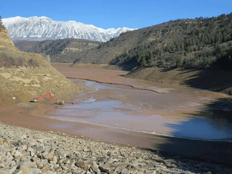
Reservoir Sedimentation Challenges
Storage Capacity Loss
Sediment accumulation gradually reduces available reservoir storage, affecting water supply reliability:
- Typical annual capacity loss: 0.5-1% per year for most reservoirs
- Range observed globally: 0.05-4% annually depending on watershed conditions
- Many facilities experience losses clustering between 0.36-0.66% per year
- Over 20-50 years, cumulative losses become operationally significant
- Some aggressive sedimentation cases lose 10-20% capacity per decade
Operational Implications:
- Reduced drought reserves threaten supply reliability
- Limited flood control capacity increases downstream risk
- Changed intake depth relationships affect water quality
- Eventual need for expensive dredging or capacity expansion
- Reduced flexibility in managing source water quality
Natural Lakes vs. Engineered Reservoirs
Analysis of hundreds of water bodies worldwide reveals opposite trends:
Natural Lakes (83% show increasing rates):
- Sedimentation rates often 2-10 times higher than historical baselines
- Increases driven primarily by watershed land use changes
- Agricultural development and urbanization accelerate erosion
- Climate factors contribute but land use changes dominate
Engineered Reservoirs (54% show declining rates):
- Success attributed to active watershed management programs
- Upstream dams trap sediment before reaching main storage
- Conservation practices implemented in contributing watersheds
- Demonstrates that management interventions can reverse negative trends
This divergence proves that sedimentation isn’t inevitable—proper watershed management successfully reduces rates even as surrounding regions experience increases.
Watershed Impacts on Source Water Quality
Land Use Effects on Sedimentation
What happens upstream directly determines sediment loads reaching reservoirs and treatment plants:
Agricultural Development:
- Conversion to cropland increases sediment loads 10-100 times over forested conditions
- Cultivation on steep slopes creates especially severe erosion
- Bare soil periods between planting and crop cover establishment
- Loss of riparian vegetation removes natural filtration
- Heavy machinery compacts soil, increasing runoff velocity
Urban Expansion:
- Impervious surfaces increase runoff velocity and sediment transport capacity
- Construction activities generate massive temporary sediment loads
- Modified drainage networks concentrate flows instead of distributing naturally
- Residential development increase from 14% to 21% of watershed area can result in 62% increase in annual sediment delivery
Infrastructure Development:
- Road construction and maintenance expose bare soil
- River channelization increases flow velocities and erosive power
- Logging operations disturb forest floor and remove stabilizing vegetation
- Mining activities create large areas of disturbed, erodible material
Climate Factors:
While land use dominates, climate patterns amplify or moderate sedimentation:
- Intense rainfall events mobilize more soil per storm
- Seasonal patterns affect vegetation cover and soil moisture
- Temperature changes influence decomposition rates and vegetation growth
- Combined effects: Land use change plus increased rainfall intensity can multiply sediment generation beyond either factor alone
Successful Watershed Management Approaches
Many water utilities have successfully reduced reservoir sedimentation through partnerships and watershed investments. Documented results prove the effectiveness of these strategies:
Upstream Conservation Programs
Reforestation and Land Use Conversion:
- Forest land increase to 55% of watershed area: 48% reduction in annual sediment yield documented
- Natural recovery of abandoned farmland (22% of basin): 25% reduction in runoff measured
- Conversion of steep farmland to forest particularly effective
- Programs typically require 5-15 years to show measurable benefits
- Long-term effectiveness improves as vegetation matures
Agricultural Best Management Practices:
- Conservation tillage reduces soil disturbance and maintains cover
- Retention terracing reduces sediment yield by 65% and runoff by 78% in documented cases
- Riparian buffers filter runoff before reaching streams
- Cover crops during off-seasons prevent bare soil exposure
- Contour farming reduces slope-driven erosion
Structural Controls
- Small upstream check dams capture sediment before reaching main reservoir
- Retention basins trap coarse material during high-flow events
- Sediment bypass systems route high-concentration flows around reservoir during storms
- Strategic sluice gate operation passes sediment during appropriate conditions
Reservoir Management Techniques
- Drawdown flushing mobilizes accumulated sediment during low-demand periods
- Sediment bypass tunneling routes flows past settling zones temporarily
- Modified spillway operations pass sediment-laden water during runoff events
- Coordination with upstream watershed activities maximizes effectiveness
Implications for Treatment Plant Operations
Intake Management Strategies
Understanding reservoir sedimentation and turbidity patterns allows strategic intake operation:
During Storm Events:
- High-turbidity plumes move through reservoir at predictable rates
- Strategic intake depth selection minimizes sediment loads
- Multiple intake levels provide operational flexibility to avoid worst conditions
- Continuous monitoring helps predict when turbidity will reach each intake elevation
- Coordination with upstream releases improves response timing
Seasonal Patterns:
- Spring runoff typically carries highest annual sediment loads
- Summer stratification can trap turbidity at thermocline depths
- Fall turnover redistributes accumulated sediment throughout water column
- Winter typically provides best raw water quality in most climates
- Historical pattern analysis guides operational planning
Operational Adjustments for Source Water Variability:
- Increase coagulant doses 2-5x during high-turbidity events
- Switch intake depths when multiple elevations are available
- Coordinate with reservoir operators on controlled releases
- Plan major maintenance for seasons with predictably better raw water
- Maintain adequate chemical inventory for extended poor-quality periods
- Consider temporary process modifications during extreme events
Long-Term Planning Considerations
Intake Structure Design
New facilities and major rehabilitations should incorporate flexibility for changing conditions:
- Multiple intake depths separated by 10-20 feet vertical
- Ability to isolate and clean individual intakes without service interruption
- Provisions for future deepening as sediment accumulates over decades
- Adequate capacity at higher elevations for low-reservoir operations
- Screens and traveling screens sized for worst-case debris loads
Treatment Capacity Planning
- Design for worst-case turbidity events (99th percentile, not average)
- Adequate clarifier and filter capacity during peak load periods
- Chemical feed system capacity for maximum anticipated demands
- Residuals handling sized for maximum solids production scenarios
- Storage capacity for chemicals to weather supply disruptions during crises
Watershed Coordination and Partnerships
Successful utilities actively participate in watershed management:
- Engage in regional watershed planning processes
- Support conservation program funding through rates or capital budgets
- Monitor land use trends and proposed major developments
- Establish partnerships with agricultural agencies and forestry departments
- Participate in soil conservation district activities
- Fund education programs for watershed residents
Climate Change Adaptation
- Consider regional precipitation intensity projections (many areas expecting more extreme events)
- Plan for more variable raw water quality year-to-year and within seasons
- Design flexibility into treatment processes for changing conditions
- Include provisions for future process additions if conditions deteriorate
- Evaluate adequacy of existing storage under changing hydrology
Economic Considerations
Cost of Inaction
Ignoring watershed conditions imposes significant costs on utilities:
- Reservoir dredging: $5-50 per cubic yard depending on access and disposal requirements
- Treatment costs increase 20-50% when processing poor source water
- Filter run times reduced by 30-70% during high-turbidity events
- Excessive chemical use during problem periods (2-5x normal doses)
- Shortened equipment and media life due to abrasion and fouling
- Higher residuals disposal costs and potential regulatory issues
Return on Watershed Investment
Watershed protection programs consistently show excellent returns:
- Typical ROI: $4-10 saved in treatment costs for every $1 invested in watershed management
- Reduced chemical costs compound annually over program life
- Extended filter media and equipment life reduces capital costs
- Lower residuals production reduces disposal expenses
- Avoided or deferred dredging costs
- Improved source water reliability and drought resilience
Partnership and Funding Opportunities
- Cost-sharing with agricultural conservation agencies
- Joint projects with soil and water conservation districts
- Regional water quality trading programs (selling or buying credits)
- Federal and state grants for source water protection
- Foundation funding for watershed restoration
- Partnerships with land trusts for conservation easements
Many successful utilities invest 1-3% of annual operating budget in watershed management, finding that this investment reduces overall costs while improving reliability and compliance margins. The payback period typically ranges from 3-7 years, after which benefits continue indefinitely.
Design Calculations and Sizing
Proper clarifier sizing requires calculating key parameters based on flow rates, desired removal efficiency, and site-specific conditions. Understanding these calculations helps operators optimize existing systems and engineers design new facilities.
Overflow Rate Calculation
Overflow rate (also called surface loading rate) determines the required surface area:
Formula: OFR = Q / A
Where:
- OFR = Overflow rate (gpd/ft² or m³/m²/day)
- Q = Flow rate (gpd or m³/day)
- A = Required surface area (ft² or m²)
Example Calculation:
A primary clarifier treats 2.0 million gallons per day (MGD). Using a target overflow rate of 800 gpd/ft²:
A = Q / OFR = 2,000,000 gpd / 800 gpd/ft² = 2,500 ft²
For a rectangular clarifier with length:width ratio of 4:1:
- Width = √(2,500 / 4) = 25 feet
- Length = 4 × 25 = 100 feet
Detention Time Calculation
Formula: τ = V / Q
Where:
- τ = Detention time (hours)
- V = Tank volume (gallons)
- Q = Flow rate (gallons per hour)
Example Calculation:
For the 2,500 ft² clarifier above with 12-foot depth:
Volume = 2,500 ft² × 12 ft × 7.48 gal/ft³ = 224,400 gallons
Q = 2,000,000 gpd / 24 hr/day = 83,333 gph
τ = 224,400 gal / 83,333 gph = 2.69 hours
This exceeds the minimum 2-hour requirement for primary clarifiers.
Weir Loading Rate
Weir loading affects effluent quality by determining velocity over outlet weirs:
Formula: WLR = Q / L
Where:
- WLR = Weir loading rate (gpd/ft)
- Q = Flow rate (gpd)
- L = Total weir length (ft)
Typical values:
- Primary clarifiers: 10,000-20,000 gpd/ft
- Secondary clarifiers: 15,000-25,000 gpd/ft
Troubleshooting Common Sedimentation Problems
Even well-designed systems experience performance issues. Recognizing symptoms and understanding root causes allows rapid correction.
High Effluent Turbidity
Possible Causes:
- Inadequate chemical dose or poor mixing
- Hydraulic overload exceeding design capacity
- Short-circuiting due to poor inlet design or baffling
- Rising sludge from denitrification or septicity
- Density currents carrying solids to outlet
Corrective Actions:
- Perform jar tests to verify optimal chemical dose
- Check and adjust flocculation mixing speed
- Inspect inlet baffling for damage or bypassing
- Increase sludge removal frequency to prevent anaerobic conditions
- Consider installing additional outlet weirs to improve distribution
Blanket Control Problems
Excessive Blanket Depth:
- Reduces effective settling volume
- Increases risk of solids carryover to effluent
- Can create anaerobic zones leading to rising sludge
Solution: Increase sludge withdrawal rate or frequency
Insufficient Blanket:
- Wastes clarifier capacity
- Provides minimal thickening
- May indicate poor settling or excessive withdrawal
Solution: Reduce withdrawal rate, check chemical dosing, verify floc formation
Density Currents
Symptoms:
- Temperature differences create horizontal flows
- Cold influent sinks and flows along bottom to outlet
- Warm influent floats and flows across surface
- Carries unsettled particles directly to effluent
Solutions:
- Install baffles to interrupt current flow
- Adjust inlet location or add multiple inlets
- Consider heating or cooling influent in extreme cases
- May be unavoidable seasonally—increase chemical doses during problem periods
Sediment in Residential Water Systems
While this guide focuses on municipal and industrial applications, sediment issues also affect residential systems. Common residential issues include:
- Sediment in well water from geological sources or surface infiltration
- Mineral buildup in water heaters reducing efficiency and capacity
- Sediment accumulation in hot water lines causing reduced flow
- Sediment filters and whole-house filtration systems for homeowners
- Water softeners to prevent mineral-related sediment formation
For most residential applications, sediment filters rated at 5-20 microns effectively remove particles. Regular maintenance including periodic water heater flushing helps prevent excessive buildup.
Environmental Impact of Sediment
Sediment pollution affects water quality and aquatic ecosystems beyond just treatment plant operations. Understanding these broader impacts helps justify watershed protection investments and comprehensive sediment management programs.
Water Quality Effects
Sediment acts as both a pollutant itself and a carrier for other contaminants:
- Increased Turbidity: Suspended particles make water cloudy, reducing sunlight penetration needed for aquatic plant photosynthesis
- Pollutant Transport: Sediment carries absorbed pesticides, heavy metals, nutrients, and bacteria
- Dissolved Oxygen Depletion: Decomposing organic matter in sediment consumes oxygen
- Temperature Effects: Suspended sediment absorbs solar radiation, warming water and reducing oxygen solubility
Aquatic Life Impacts
- Gill Damage: Fine particles clog fish gills, impairing respiration
- Reduced Visibility: Turbidity interferes with predator-prey relationships and fish feeding
- Habitat Degradation: Sediment fills spaces between rocks where fish spawn and aquatic insects live
- Smothering: Heavy sedimentation can bury eggs, benthic organisms, and bottom-dwelling species
- Food Chain Disruption: Reduced light limits primary production at the base of food webs
Infrastructure and Economic Impacts
- Reservoir and Navigation Channel Filling: Requires expensive dredging to maintain capacity and depth
- Increased Water Treatment Costs: Higher turbidity demands more chemicals and energy
- Damage to Equipment: Abrasive sediment wears pumps, valves, and piping
- Recreation and Tourism: Murky water and degraded fisheries reduce recreational value
- Flood Risk: Sediment accumulation reduces flood storage and conveyance capacity
Comprehensive sediment management that addresses both treatment plant performance and watershed conditions provides benefits extending far beyond individual facility operations. Programs that reduce sediment loads improve source water quality, protect aquatic ecosystems, and reduce long-term infrastructure costs.
Learn more about sediment pollution impacts from the U.S. Environmental Protection Agency.
Frequently Asked Questions About Sedimentation
What is sedimentation in water treatment?
Sedimentation is a physical water treatment process that uses gravity to remove suspended particles from water. Particles heavier than water settle to the bottom of a tank (clarifier or sedimentation basin) where they can be collected and removed. The clarified water then flows over weirs for further treatment or discharge. Sedimentation typically removes 50-95% of suspended solids depending on whether chemical coagulants are used.
What are the four types of sedimentation?
The four types are classified by particle concentration and behavior: (1) Discrete settling – individual particles settle independently in dilute suspensions; (2) Flocculent settling – particles collide and aggregate during descent, common after chemical coagulation; (3) Zone settling – particles settle as a mass with a distinct interface, typical in secondary clarifiers; and (4) Compression settling – particles are in contact and compress under their own weight, found in thickener bottoms.
What is the difference between primary and secondary sedimentation?
Primary sedimentation removes settleable solids from raw wastewater before biological treatment, typically achieving 50-70% suspended solids removal and 25-40% BOD reduction. Secondary sedimentation (clarification) follows biological treatment to separate microorganisms from treated water while thickening biological solids for return to the aeration process. Secondary clarifiers must handle higher solids concentrations and require both adequate hydraulic capacity and solids loading capacity.
How long does sedimentation take in water treatment?
Detention time varies by application: primary clarifiers typically provide 1.5-2.5 hours, secondary clarifiers 2-4 hours, and drinking water clarifiers 2-6 hours depending on design. High-rate settlers using lamella plates or tube settlers can achieve adequate performance with 0.5-1 hour detention. The required time depends on particle characteristics, chemical treatment, temperature, and desired removal efficiency.
What is overflow rate in sedimentation?
Overflow rate (surface loading rate) is the flow rate divided by surface area, typically expressed in gallons per day per square foot (gpd/ft²). It represents the upward water velocity that settling particles must overcome. Primary clarifiers typically use 600-1,200 gpd/ft², while secondary clarifiers use 400-800 gpd/ft². Lower overflow rates provide greater factors of safety and better performance during variable conditions.
How do chemicals improve sedimentation?
Coagulants like aluminum sulfate (alum) and polymers dramatically improve sedimentation by promoting particle aggregation. Coagulants neutralize surface charges that keep particles dispersed, allowing them to approach and combine into larger flocs. These flocs settle 5-10 times faster than individual particles. Chemical addition can increase suspended solids removal from 50-60% up to 85-95%.
What factors affect settling velocity?
Settling velocity depends on particle size, density, shape, and water properties. Larger and denser particles settle faster. Water temperature affects viscosity—cold water (0°C) has twice the viscosity of warm water (25°C), slowing settling rates significantly. Organic matter content reduces floc density, sometimes offsetting the benefit of increased size. Turbulence and short-circuiting can prevent particles from settling regardless of their theoretical settling velocity.
What causes poor sedimentation performance?
Common causes include inadequate chemical dosing, poor mixing during coagulation or flocculation, hydraulic overload, short-circuiting, density currents, rising sludge from denitrification, excessive sludge blanket depth, and cold water temperatures. Troubleshooting requires systematic evaluation of chemical dosing (through jar tests), hydraulic conditions, sludge management, and upstream treatment processes.
How do you calculate clarifier size?
Surface area equals flow divided by overflow rate: A = Q / OFR. For example, a 2 MGD (2,000,000 gpd) flow with an 800 gpd/ft² overflow rate requires 2,500 ft² surface area. Depth is then selected based on detention time requirements (typically 10-16 feet). Volume equals surface area times depth. Secondary clarifiers also require verification that solids loading doesn’t exceed recommended limits (typically 20-40 lb/day/ft²).
What is the difference between sedimentation and filtration?
Sedimentation uses gravity to remove heavier particles in a quiescent basin, while filtration passes water through porous media (sand, anthracite, membranes) to physically strain out particles. Sedimentation typically precedes filtration in treatment trains because it removes larger particles cost-effectively, protecting filters from rapid fouling. Sedimentation removes 85-95% of particles with chemical treatment; filtration then removes remaining fine particles to achieve <0.3 NTU turbidity.
How does temperature affect sedimentation?
Cold temperatures create multiple challenges: increased water viscosity (up to 100% higher at 0°C vs 25°C) slows settling, reduced chemical reaction rates require longer contact times, and some coagulants (especially alum) become less effective below 5°C. Operators compensate by increasing chemical doses 1.5-2x, allowing longer flocculation times, and reducing overflow rates when possible. Conversely, warm water settling is faster but may experience more biological activity and algae growth.
What is a sludge blanket and how should it be managed?
A sludge blanket is the accumulated layer of settled solids at the bottom of a clarifier. In secondary clarifiers, maintaining an appropriate blanket depth (typically 2-4 feet) helps thicken solids before return or waste. Too deep reduces effective settling volume and risks solids carryover; too shallow wastes capacity and provides minimal thickening. Operators monitor blanket depth and adjust sludge withdrawal rates to maintain target depths.
How does organic matter affect floc formation?
Organic matter, particularly extracellular polymeric substances (EPS) produced by microorganisms, acts as a natural flocculant that binds particles together. This can improve floc size but reduces density, sometimes resulting in slower settling despite larger flocs. Seasonal variations in biological activity (spring/summer algae blooms vs winter dormancy) create corresponding changes in floc characteristics, requiring operators to adjust chemical doses and monitor performance closely during transitions.
What is ballasted flocculation?
Ballasted flocculation adds microsand (fine sand particles) to create weighted flocs that settle 10 times faster than conventional flocs (3-5 m/h vs 0.5-1 m/h). This enables 75% footprint reduction and detention times of just 30-60 minutes. The microsand is recovered and recycled within the process. Applications include high-turbidity event treatment, combined sewer overflow treatment, and facilities requiring compact design or rapid response to load changes.
Why invest in watershed management for a water utility?
Watershed protection consistently shows return on investment of $4-10 saved in treatment costs for every $1 invested. Benefits include reduced chemical costs, extended filter runs, lower residuals disposal expenses, avoided dredging costs, and improved drought reliability. Treatment costs can increase 20-50% when processing poor source water. Many successful utilities invest 1-3% of operating budget in watershed programs, with payback periods of 3-7 years.
Learn more about sediment pollution from the U.S. Environmental Protection Agency.
Frequently Asked Questions
Sedimentation is a key process used in water treatment to remove particles. It also occurs naturally in environments like rivers and lakes. There are different tanks designed for this purpose in wastewater management.
How does the sedimentation process work in water treatment?
In water treatment, sedimentation helps to remove suspended solids from water. Water flows into a tank where it slows down. The heavier particles then settle at the bottom due to gravity. This process is crucial for improving water clarity before further treatment steps.
Can you illustrate sedimentation in natural environments?
Sedimentation occurs naturally when particles settle in bodies of water like rivers and lakes. For instance, when a river carries soil downstream, the soil particles eventually settle at the riverbed. This process forms sediments that can alter the river's shape over time.
What are the types of sedimentation tanks used in wastewater management?
There are several types of sedimentation tanks used in wastewater management:
Rectangular Tanks: These are long and divided into separate sections to allow particles to settle.
Circular Tanks: These have a radial flow path that promotes settling in the center.
Upflow Tanks: Water flows upward, allowing particles to settle at the base.
Each type is designed for specific uses and efficiency levels in treating wastewater.