Screw Pump VFD Setup: Preventing Overheating
1. Introduction
In the water and wastewater industry, the failure of screw pumps—whether large Archimedes lift pumps or progressive cavity sludge pumps—often stems not from hydraulic inadequacy, but from thermal mismanagement of the drive system. A surprising statistic from motor reliability studies indicates that for every 10°C rise in operating temperature above the rated limit, the insulation life of a motor winding is cut in half. Yet, engineers frequently specify Variable Frequency Drives (VFDs) for screw pumps without accounting for the unique thermal physics of constant torque loads running at reduced speeds.
This oversight leads to a critical specification mistake: treating screw pumps like centrifugal pumps. While centrifugal pumps benefit from the affinity laws (where torque drops significantly with speed), screw pumps maintain near-constant torque requirements regardless of RPM. Consequently, a standard Screw Pump VFD Setup: Preventing Overheating requires a fundamentally different approach to sizing, cooling, and parameterization than the typical centrifugal pump application found elsewhere in the plant.
This article is designed for municipal engineers, plant superintendents, and reliability professionals. It moves beyond basic product catalogs to address the engineering required to prevent thermal degradation in the motor, the VFD, and the pump stator. Proper setup ensures asset longevity, reduces unscheduled downtime in critical lift stations and dewatering processes, and optimizes the lifecycle cost of the equipment.
2. How to Select / Specify
Preventing overheating begins at the specification stage. The interaction between the VFD and the screw pump motor creates thermal challenges that must be mitigated through precise engineering choices.
Duty Conditions & Operating Envelope
The operating envelope of a screw pump is the primary driver of thermal stress. Unlike centrifugal pumps, Archimedes and Progressive Cavity (PC) pumps are Constant Torque loads. This means the current required to turn the rotor remains relatively high even at low speeds.
- Torque Characteristics: Specify VFDs rated for “Constant Torque” or “Heavy Duty” rather than “Variable Torque” or “Normal Duty.” A Variable Torque drive is designed for fans and centrifugal pumps; if applied to a screw pump, it may lack the current overload capacity required for startup or clearing minor jams, leading to drive overheating and nuisance tripping.
- Turndown Ratios: Define the minimum operating speed. If a pump must operate at 15Hz (4:1 turndown) for extended periods, standard Totally Enclosed Fan Cooled (TEFC) motors may overheat because the shaft-mounted fan is turning too slowly to move sufficient air.
- Ambient Conditions: In wastewater treatment plants, screw pumps are often located outdoors or in non-climate-controlled headworks. The specification must account for ambient temperatures exceeding 40°C in summer, which de-rates the VFD’s current carrying capacity.
Materials & Compatibility
The materials selected for the motor and cabling play a crucial role in resisting thermal breakdown caused by VFD operation.
- Insulation Class: Specify NEMA MG1 Part 31 Inverter Duty motors with, at minimum, Class F insulation (rated for 155°C) but designed to operate within Class B temperature rise limits (80°C rise). This provides a thermal safety margin.
- Cable Insulation: VFD output creates voltage spikes (reflected waves) that can degrade cable insulation, causing leakage currents and heating. Use shielded VFD cable with XLPE insulation rather than standard THHN, specifically for runs exceeding 50 feet.
- Bearing Protection: While not strictly “overheating,” electrical discharge machining (EDM) caused by VFD-induced shaft voltages creates friction heat and bearing failure. Specify shaft grounding rings for motors over 10 HP to mitigate this.
In Progressive Cavity pumps, “overheating” also applies to the elastomeric stator. If the VFD is set up without dry-run protection, the friction between the steel rotor and the dry rubber stator causes rapid thermal expansion and catastrophic destruction of the elastomer. VFD power monitoring is the first line of defense against this mechanical overheating.
Installation Environment & Constructability
The physical location of the VFD relative to the screw pump impacts thermal performance.
- VFD Cooling: Drive cabinets generate significant heat (roughly 2-3% of the connected load). If the VFD is housed in a NEMA 4X outdoor enclosure, passive cooling is rarely sufficient for drives above 50 HP. Specify active cooling (air conditioners or forced air heat exchangers) to prevent the drive internals from reaching thermal shutdown limits.
- Cable Length: Long cable runs between the VFD and the screw pump motor act as capacitors, increasing voltage spikes. This stresses the motor insulation thermally. For runs over 100 feet, specify a dV/dt filter; for runs over 300 feet, a sine wave filter is mandatory to reduce motor heating.
Reliability, Redundancy & Failure Modes
To ensure system reliability, the design must anticipate thermal failure modes.
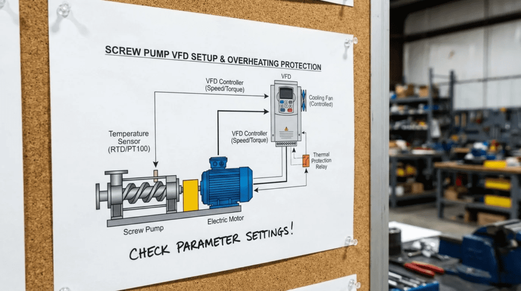
- Motor Thermistors: Do not rely solely on the VFD’s calculated electronic thermal overload. Specify Positive Temperature Coefficient (PTC) thermistors or RTDs embedded directly in the motor windings. These should be wired back to the VFD or a separate monitoring relay to trip the drive based on actual winding temperature.
- Backup Cooling: For critical lift stations using large Archimedes screws, consider specifying motors with independent blower cooling (TEBC/TEAO). This ensures maximum airflow across the motor fins even when the VFD is running the pump at 10% speed.
Controls & Automation Interfaces
The VFD is an intelligent sensor that can be leveraged to prevent overheating.
- Torque Monitoring: Map the VFD’s torque output to SCADA. A sudden drop in torque at a fixed speed often indicates a broken coupling or dry run (for PC pumps), while a slow rise in torque over months may indicate ragging or debris buildup, which increases thermal load.
- Temperature Integration: If the motor has RTDs, integrate these into the PLC logic. Set a “Warning” alarm at 130°C and a “Trip” alarm at 155°C (for Class F). This allows operators to intervene before insulation damage occurs.
Lifecycle Cost Drivers
Investing in thermal management upfront reduces Total Cost of Ownership (TCO).
- Energy Efficiency: While VFDs save energy, an overheated motor increases resistance and lowers efficiency. A motor running 10°C hotter than necessary increases resistive losses ($I^2R$).
- Replacement Costs: Rewinding a large screw pump motor is expensive and requires crane mobilization. The cost of a dV/dt filter or an auxiliary cooling fan is typically less than 5% of the cost of a single motor failure.
3. Comparison Tables
The following tables assist engineers in selecting the correct motor cooling strategy and understanding the thermal implications of different screw pump technologies. Use Table 1 to select the motor enclosure type based on your VFD speed range, and Table 2 to evaluate application suitability.
| Cooling Method / Enclosure | Cooling Mechanism | Best-Fit Speed Range | Thermal Limitations | Typical Maintenance |
|---|---|---|---|---|
| TEFC (Totally Enclosed Fan Cooled) | Shaft-mounted fan. Airflow is proportional to motor speed. | 40 Hz – 60 Hz (2:1 Turndown or less) | High Risk: At low speeds (<30Hz), airflow is negligible. Motor will overheat at full torque. | Clean fan shroud; inspect plastic fan blades for brittleness. |
| TEBC / TEAO (Blower Cooled / Air Over) | Independent electric blower fan runs at constant speed regardless of motor RPM. | 0 Hz – 60 Hz (Infinite Turndown) | Low Risk: Provides maximum cooling even at stall/zero speed. Ideal for VFD setups. | Maintain secondary blower motor; clean filters if equipped. |
| TENV (Totally Enclosed Non-Ventilated) | Passive radiation and convection only. No fan. | Variable (Requires significant de-rating) | Medium Risk: Motor must be massively oversized to dissipate heat without airflow. | Keep cooling fins free of dust/sludge buildup to ensure heat transfer. |
| Submersible (Immersed) | Heat transfer to the pumped media (wastewater). | Variable | Conditional Risk: If pump runs dry or un-submerged, cooling is lost immediately. Requires cooling jacket for dry pit use. | Monitor seal oil; ensure liquid level sensors prevent un-submerged operation. |
| Pump Technology | Load Type | Primary Thermal Risk | VFD Control Strategy to Prevent Overheating | Relative Cost Impact |
|---|---|---|---|---|
| Archimedes Screw (Open) | Constant Torque | Motor winding overheat at low RPM (lack of airflow). | Set Minimum Frequency > 20Hz (for TEFC) or use TEBC motors. | $$ (Due to large gearboxes and motors) |
| Progressive Cavity (Enclosed) | Constant Torque | Stator burn-out due to dry run; Motor overheat due to high viscosity/drag. | Active torque monitoring to trip on low load (dry run). | $$$ (Stators are expensive consumables) |
| Centrifugal (Dry Pit) | Variable Torque | Impeller heat recirculation at shut-off head. | Minimum flow logic; sleep mode on low demand. | $ (Standard motors/drives usually suffice) |
4. Engineer & Operator Field Notes
Real-world experience often deviates from the clean lines of a specification sheet. The following section details practical steps for commissioning and maintaining Screw Pump VFD Setup: Preventing Overheating.
Commissioning & Acceptance Testing
During startup, the “set it and forget it” mentality is the enemy of thermal longevity. The Factory Acceptance Test (FAT) and Site Acceptance Test (SAT) must verify thermal parameters.
- Current Verification: Run the screw pump at 25%, 50%, 75%, and 100% speed. Measure the amperage and compare it to the motor nameplate. In Archimedes screws, the current should remain relatively flat or decrease slightly, but should never exceed Full Load Amps (FLA) multiplied by the Service Factor.
- Temperature Rise Test: If using RTDs, monitor the winding temperature stabilization during the SAT. If the temperature rises rapidly at low speeds, the minimum frequency (Min Hz) is set too low for the cooling method employed.
- Carrier Frequency Optimization: The VFD carrier frequency (switching frequency) is a compromise. Higher frequencies (e.g., 8-12 kHz) reduce audible motor noise but increase heat in the VFD (IGBTs). Lower frequencies (e.g., 2-4 kHz) run the VFD cooler but may cause higher motor heating due to harmonics. Recommendation: Start at 2-4 kHz for screw pumps. The industrial environment tolerates the noise, and the lower switching losses help the VFD stay cool.
Common Specification Mistakes
Avoid these recurring errors in bid documents:
- Specifying VT Drives: Engineers often copy specs from centrifugal pump sections. A Variable Torque drive applied to a screw pump will struggle to provide starting torque and will run hotter due to higher current demands relative to its rating. Always specify Constant Torque (CT) ratings.
- Ignoring Elevation: VFDs and motors are typically rated for 1000m (3300ft) elevation. If the plant is at higher altitude, the thinner air reduces cooling capacity. Both the drive and motor must be de-rated or oversized to prevent overheating.
- Oversizing Without Adjustment: Oversizing a VFD (e.g., 100HP drive on 75HP motor) provides a safety margin, but if the motor parameters are not entered correctly, the VFD may not protect the motor from thermal overload effectively.
When running a motor on a VFD, the Service Factor (typically 1.15 on sine wave power) effectively becomes 1.0. Do not design the system to run continuously into the service factor when using a VFD. The harmonic heating eliminates the thermal margin that the service factor usually provides.
O&M Burden & Strategy
Maintenance directly impacts thermal performance.
- Filter Maintenance: The number one cause of VFD overheating is clogged intake filters on the enclosure. Implement a monthly PM to inspect and replace/wash filters.
- Greasing Intervals: High temperatures degrade grease. If the motor runs hot (e.g., 70°C+ casing temp), shorten the bearing regreasing interval. Follow the manufacturer’s chart for “Severe Duty.”
- Heat Sink Cleaning: For Archimedes screws located outside, the VFD heat sink can accumulate pollen, dust, and spider webs. Clean the heat sink fins annually with compressed air to maintain thermal dissipation.
Troubleshooting Guide
- Symptom: Motor Overload Trip at Low Speed.
Root Cause: Insufficient torque boost or insufficient cooling.
Action: Check if the VFD is in “Sensorless Vector” mode (preferred) rather than “V/Hz.” Verify the cooling fan is effective. - Symptom: VFD Over-Temp Trip.
Root Cause: High ambient temp, clogged filters, or carrier frequency too high.
Action: Lower carrier frequency to 2 kHz. Clean filters. Check cabinet AC unit.
5. Design Details / Calculations
Engineering the setup requires calculating the safe operating limits.
Sizing Logic & Methodology
To ensure thermal stability, sizing must account for the worst-case torque scenario.
- Determine Breakaway Torque: Screw pumps, especially those settling with sludge, can require 150% to 200% of nominal torque to start. The VFD must be sized to deliver this current for up to 60 seconds without overheating the IGBTs.
- Calculate Heat Load:
VFD Heat Loss (Watts) ≈ 0.03 × Drive kW Rating × 1000.
Ensure the enclosure cooling (BTU/hr) exceeds this value plus solar gain. - De-rating for Harmonics: If no harmonic filters are present, the motor will run 5-10°C hotter due to harmonic currents. Select a motor one frame size larger or with Class H insulation to compensate.
Specification Checklist
Include these items in Division 26 (Electrical) or Division 40 (Process Interconnections):
- Motor: Inverter Duty, Constant Torque 10:1 (minimum), Class F or H insulation, 1.15 SF (sine wave), thermostat/thermistor embedded.
- VFD: Constant Torque rating, 110% overload for 1 minute, coated circuit boards (conformal coating) to resist H2S corrosion which causes hotspots.
- Cabling: Shielded VFD cable with 100% coverage ground braid.
Standards & Compliance
- NEMA MG1 Part 31: Defines the insulation requirements for motors operated on adjustable speed drives. Essential for preventing insulation dielectric breakdown and thermal failure.
- IEEE 519: Governs harmonic distortion. High harmonics cause heating in transformers and motors. Compliance usually requires line reactors or active front-end drives.
- UL 508A: Standard for industrial control panels, ensuring thermal management within the enclosure is safe and certified.
6. Frequently Asked Questions
What is the minimum speed a screw pump can run on a VFD without overheating?
For a standard TEFC (Totally Enclosed Fan Cooled) motor, the typical minimum speed is 20-25 Hz (approx. 30-40% speed). Below this, the shaft fan cannot generate enough airflow to cool the windings under constant torque load. If operation below 20 Hz is required, you must specify a TEBC (Totally Enclosed Blower Cooled) motor or oversized TENV motor. Always consult the motor manufacturer’s thermal capability curve.
Why does my Progressive Cavity pump stator overheat when controlled by a VFD?
Stator overheating in Progressive Cavity pumps is usually caused by dry running (running without fluid). The elastomer stator requires the fluid for lubrication and heat dissipation. A VFD can prevent this by enabling “Under-Load” or “Loss of Load” protection. If the torque drops below a set threshold (indicating air/dry run), the VFD should trip immediately to save the stator.
Does carrier frequency affect Screw Pump VFD overheating?
Yes. The carrier frequency (switching speed of the transistors) involves a tradeoff. A high carrier frequency (e.g., 10 kHz) makes the motor quieter but generates significantly more heat in the VFD unit itself. A low carrier frequency (e.g., 2.5 kHz) keeps the VFD cooler but sends “rougher” power to the motor, which can slightly increase motor temperature and audible noise. For screw pumps, lower carrier frequencies (2-4 kHz) are generally preferred to protect the drive.
Do I need a VFD-rated motor for a screw pump retrofit?
Yes. Older general-purpose motors often lack the insulation quality to withstand the voltage spikes and thermal stress of VFD operation, leading to rapid winding failure. If you cannot replace the motor, you must install a dV/dt filter or a sine wave filter between the VFD and the motor to protect the old insulation, though this adds cost and heat load to the electrical room.
What is the difference between Variable Torque and Constant Torque VFDs for screw pumps?
Screw pumps are Constant Torque loads, meaning they require full twisting force to lift the water regardless of how fast they are turning. Variable Torque (VT) drives are designed for fans and centrifugal pumps where torque drops as speed drops. Using a VT drive on a screw pump will often result in the drive overheating or tripping on overload at lower speeds. You must specify Constant Torque (CT) VFDs.
How do I integrate motor temperature sensors with a VFD?
Most modern industrial VFDs have dedicated analog inputs or PTC inputs for motor thermal protection. You can wire the motor’s embedded thermistors (PTC) or RTDs directly to the drive. You then program the VFD to trigger a “Warning” at a lower temperature (e.g., 130°C) and a “Fault/Trip” at the insulation limit (e.g., 155°C). This is superior to relying on the VFD’s mathematical thermal model.
7. Conclusion
Key Takeaways
- Physics Matter: Screw pumps are Constant Torque loads. Always specify VFDs with Constant Torque / Heavy Duty ratings.
- Cooling at Low Speed: Standard TEFC motors may overheat below 20-25 Hz. Use Blower Cooled (TEBC) motors for wide turndown ranges.
- Protect the Stator: For Progressive Cavity pumps, enable VFD “Under-Torque” protection to prevent dry-run burnout.
- Manage Harmonics: Use dV/dt filters for long cable runs and keep carrier frequencies low (2-4 kHz) to manage VFD heat.
- Monitor Reality: Use embedded motor sensors (RTDs/PTCs) for thermal protection, not just the VFD’s calculated model.
Successful Screw Pump VFD Setup: Preventing Overheating requires a departure from standard centrifugal pump specifications. By recognizing the constant torque nature of the application and the limitations of motor cooling at low speeds, engineers can design systems that last decades rather than years.
The decision framework is straightforward: match the motor cooling to the speed range, size the drive for the starting torque, and utilize the VFD’s intelligence to monitor both electrical and mechanical thermal indicators. When these elements align, the screw pump becomes one of the most reliable and efficient assets in the wastewater treatment process. For complex lift stations or high-solids sludge handling, consulting with drive specialists to model the thermal load profile is a recommended final step before issuance for construction.