Vertical Turbine Pump Curve Reading for Operators (BEP Runout Shutoff and Control)
Introduction
The vertical turbine pump (VTP) is the workhorse of municipal raw water intake, deep well extraction, and industrial cooling loops. However, it is also frequently the most misunderstood asset regarding hydraulic performance. Unlike standard horizontal end-suction pumps, VTPs often utilize mixed-flow hydraulics that create counter-intuitive power and pressure characteristics. A surprising number of premature failures—broken shafts, destroyed thrust bearings, and cavitation-pitted impellers—occur because the operational strategy does not align with the pump’s unique geometry. Vertical Turbine Pump Curve Reading for Operators (BEP Runout Shutoff and Control) is not merely an academic exercise; it is a critical skill set required to prevent catastrophic equipment loss and optimize energy consumption.
In municipal water treatment and industrial wastewater applications, VTPs are often subjected to varying system heads and flows. Whether installed in a wet well (can) or an open sump, the pump must operate within a specific envelope to maintain mechanical integrity. Engineering specifications often focus heavily on the design point, but the reality of plant operations means pumps spend significant time at partial loads or ramping conditions. Neglecting the specific speed characteristics of a VTP can lead to motor overloads at shutoff or upthrust damage at runout.
Proper selection requires understanding that VTP curves are generally steeper than radial flow pumps, offering distinct advantages for control but posing unique risks during start-up and valve closure. This article aims to bridge the gap between the design engineer’s theoretical curve and the operator’s daily reality, ensuring that decision-makers understand the lifecycle implications of where the pump operates relative to its Best Efficiency Point (BEP).
How to Select / Specify
Selecting the correct vertical turbine pump requires a multidimensional approach that goes beyond hitting a single flow and head target. The specification process must account for the entire operating envelope, from minimum flow to runout, ensuring the equipment can handle the full range of process conditions.
Duty Conditions & Operating Envelope
The first step in correct specification involves defining the system curve, not just a static duty point. For Vertical Turbine Pump Curve Reading for Operators (BEP Runout Shutoff and Control), understanding the interaction between the steep VTP H-Q (Head-Capacity) curve and the system curve is paramount.
Engineers must identify the static head (elevation lift) and friction losses separately. VTPs are often used in applications with high static head variation, such as drawing from aquifers or tidal basins. The selected pump must have a shutoff head significantly higher than the maximum static lift to ensure flow initiation. Furthermore, the selection must account for “runout” conditions where low static head (e.g., a full well) might push the pump far to the right of the curve, potentially causing cavitation or motor overload depending on the specific speed ($N_s$) of the impeller.
Materials & Compatibility
Material selection for VTPs is critical due to the long shaft lengths and the immersion of bearings in the process fluid. For freshwater applications, cast iron bowls with bronze impellers are standard. However, in wastewater or brackish applications, galvanic corrosion becomes a major lifecycle cost driver.
Operators reading curves should note that material wear opens running clearances, effectively shifting the pump curve down and to the left over time. Specifying 316 stainless steel or Duplex stainless steel for impellers and wear rings can preserve the hydraulic curve shape for longer periods compared to softer bronzes. In abrasive applications (e.g., raw water intake with grit), selecting open line shafts with fresh water flush is often preferable to product-lubricated enclosed line shafts to prevent bearing degradation that leads to vibration.
Hydraulics & Process Performance
This is where VTPs differ significantly from horizontal split-case pumps. VTPs often fall into the “mixed flow” specific speed range. In these designs, the horsepower curve may remain flat or even rise as flow decreases toward shutoff. This is the opposite of a standard radial centrifugal pump where power drops at shutoff.
Engineers must analyze the power curve carefully. If a VTP has a rising power characteristic at shutoff, the motor must be sized to handle the “shutoff power” to prevent tripping during closed-valve starting or accidental blockages. Additionally, the Net Positive Suction Head Required (NPSHr) rises sharply at the right side of the curve (runout). The available NPSH (NPSHa) must exceed NPSHr by a margin (typically 3-5 feet or a ratio of 1.1 to 1.3) throughout the entire operating range, not just at BEP.
Installation Environment & Constructability
VTP performance is inextricably linked to intake design. Poor sump design leads to pre-swirl, submerged vortices, and uneven velocity profiles entering the bell, which degrades the actual performance curve compared to the factory test curve.
Specifications should require adherence to Hydraulic Institute (HI) 9.8 Intake Design Standards. For “canned” or “barrel” pumps (suction cans), the engineer must ensure the can diameter provides adequate annular area to feed the suction bell without inducing high-velocity turbulence. Constructability reviews must also ensure there is sufficient overhead clearance to pull the entire vertical assembly for maintenance, a factor often overlooked in tight pump rooms.
Reliability, Redundancy & Failure Modes
Reliability in VTPs is defined by shaft stability. Operating too far left of BEP (near shutoff) creates high radial loads that deflect the long, slender shaft, causing premature bearing and seal failure. Operating too far right (runout) causes axial vibration and potential cavitation.
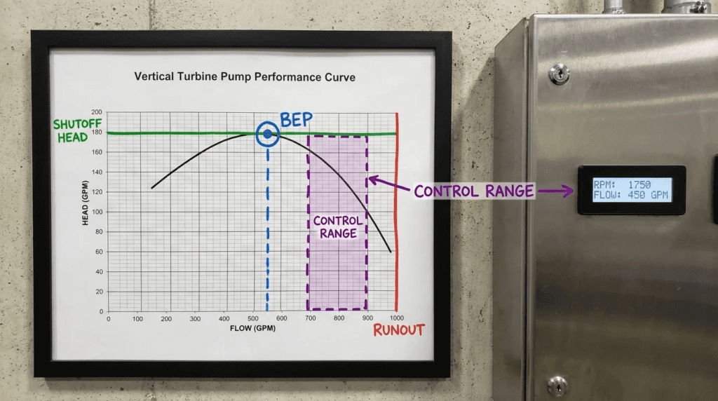
The specification should define the “Preferred Operating Region” (POR) typically between 70% and 120% of BEP, and the “Allowable Operating Region” (AOR). Redundancy strategies should act to keep pumps within the POR. For example, rather than running one pump at 130% capacity (Runout), the control system should stage on a second pump to bring both units back to an efficient 65-70% load.
Controls & Automation Interfaces
Understanding Vertical Turbine Pump Curve Reading for Operators (BEP Runout Shutoff and Control) is vital for programming VFDs. VTPs have a minimum flow requirement not just for thermal protection, but for hydraulic stability.
Because VTP curves are steep, pressure control is often more stable than flow control. However, VFDs must be programmed with a “Minimum Speed” setting that corresponds to the static head of the system. Running a VTP below the speed required to overcome static head results in zero flow while the pump churns and heats the water in the bowl assembly—a condition known as “sleep mode” failure. Automation must monitor discharge pressure or flow to confirm fluid movement.
Lifecycle Cost Drivers
While VTPs are often cheaper to install (smaller footprint) than horizontal equivalents, their maintenance can be higher if misapplied. The Total Cost of Ownership (TCO) analysis should factor in the cost of vertical motor removal and the rig required to pull the bowl assembly.
Energy efficiency is heavily dependent on maintaining tight clearances. The “lifecycle efficiency” of a VTP drops faster than other pump types if abrasive wear occurs. Specifying wear rings (both on the impeller and the bowl) allows for cost-effective restoration of the original efficiency curve during overhauls, rather than replacing expensive castings.
Comparison Tables
To assist engineers and operators in distinguishing between different vertical pump behaviors and applications, the following tables provide side-by-side comparisons. Table 1 focuses on the hydraulic characteristics based on specific speed (impeller geometry), which dictates how the curve looks. Table 2 provides an application fit matrix to help decision-makers align equipment with facility constraints.
Table 1: Vertical Pump Hydraulic Characteristics by Type
This table highlights how the “Curve” behaves differently depending on the impeller design, which is critical for operators to understand regarding power and pressure risks.
| Feature / Characteristic | Radial Flow (Low Ns) | Mixed Flow (Medium Ns) | Axial Flow (High Ns) |
|---|---|---|---|
| Typical Specific Speed ($N_s$) | 500 – 3,500 | 3,500 – 8,000 | Above 8,000 |
| Flow Direction | Perpendicular to shaft (90°) | Angular (part radial, part axial) | Parallel to shaft |
| H-Q Curve Shape | Relatively Flat | Steeper | Very Steep |
| Shutoff Head | 110% – 120% of BEP Head | 140% – 160% of BEP Head | 200% – 300% of BEP Head |
| Power Characteristic (BHP) | Drops at Shutoff (Rising to Runout) | Flat or Slight Rise at Shutoff | Sharp Rise at Shutoff (Highest power at zero flow) |
| Primary Start-up Risk | Overloading at Runout | Variable | Motor Overload at Shutoff (Must start valve open) |
| Common Application | High head, lower flow (Deep Wells) | Med head/flow (Raw Water, Cooling) | Low head, massive flow (Flood Control) |
Table 2: Application Fit Matrix
Use this matrix to identify where Vertical Turbine Pumps fit best compared to other common pumping technologies in municipal and industrial settings.
| Application Scenario | Suitability | Key Constraints | Operator Skill Impact | Relative Cost (CAPEX) |
|---|---|---|---|---|
| Deep Well Raw Water | Excellent (Standard) | Must manage drawdown and well straightness. | Moderate (Deep settings require careful start-up). | Medium |
| Finished Water High Service | Good | Requires “Can” (Suction Barrel) installation. | Low (Clean water, stable conditions). | Medium-High |
| Wastewater Influent (Raw Sewage) | Limited / Specialized | Solids handling is poor unless specialized solids-handling VTP impellers used. | High (Risk of clogging). | High (Special materials/design). |
| Stormwater / Flood Control | Excellent (Axial Flow) | Sump design is critical to prevent vortices. High shutoff power risks. | High (Must manage start-up sequence perfectly). | Low (Per GPM moved). |
| Industrial Cooling Tower | Excellent | NPSH margin is critical; basin levels fluctuate. | Moderate (Chemical compatibility issues). | Low-Medium |
Engineer & Operator Field Notes
Design theory often clashes with field reality. The following section outlines practical guidance for managing Vertical Turbine Pump Curve Reading for Operators (BEP Runout Shutoff and Control) during the commissioning and operational phases.
Commissioning & Acceptance Testing
The Factory Acceptance Test (FAT) is controlled, but the Site Acceptance Test (SAT) reveals the truth about the system curve. During SAT, it is vital to verify the “Shutoff Head” momentarily (if the specific speed allows safe operation) to anchor the pump curve against the factory data. If the field shutoff head is significantly lower than the factory curve, it indicates either a leaking check valve, damaged wear rings during installation, or incorrect impeller trim.
Vibration Baseline: VTPs are structurally flexible. Commissioning must include a resonant frequency bump test (Reed Critical Frequency) to ensure the installed natural frequency of the motor/pump structure does not align with the running speed (1x) or blade pass frequency. Establishing a vibration baseline across the full flow range is mandatory to define the safe operating window.
Common Specification Mistakes
One of the most frequent errors in specifying VTPs is neglecting the “Minimum Submergence” requirement. Engineers often confuse NPSHr (internal pump requirement to prevent cavitation) with Minimum Submergence (depth of water required above the bell to prevent surface vortices). A pump can have adequate NPSHa but still fail due to air entrainment from a surface vortex. The specification must explicitly require submergence calculations based on the bell diameter and flow velocity.
Adding too much safety margin to the head calculation often forces the VTP to operate in the “Runout” zone. If you calculate 100 ft of head but the reality is 80 ft, the pump will flow way out to the right. On a VTP, this causes Hydraulic Upthrust. The upward force of the water lifts the shaft, disengaging the thrust bearing and causing the shaft to bounce, destroying the mechanical seal and line shaft bearings.
O&M Burden & Strategy
For operators, reading the curve equates to monitoring the health of the “wet end.”
- Amperage at Shutoff: Regularly check the current draw against a closed valve (briefly). If the amperage at shutoff is dropping over time (months/years), it typically indicates that internal recirculation is increasing due to worn wear rings.
- Packing vs. Seals: Many VTPs still use packing. Operators must ensure packing is not overtightened, which scores the shaft. A steady drip is required for lubrication.
- Oil Pot Maintenance: For oil-lubricated line shafts, the solenoid oiler must be verified functional. Running dry for even a few minutes can seize the bronze line bearings.
Troubleshooting Guide: Reading the Symptoms
When a VTP acts up, the symptoms often correlate directly to where the pump is operating on its curve:
- High Vibration + Low Flow: Likely operating at Shutoff or Minimum Flow (Recirculation). This creates high radial loads.
- High Vibration + High Flow + Noise (Gravel sound): Likely operating at Runout (Cavitation). Check for low sump level or insufficient discharge head.
- High Motor Temps + Low Flow: In mixed/axial flow pumps, this indicates operation near shutoff where power consumption is highest.
- Seal Failure / Leakage: often caused by shaft wobble due to operating outside the Preferred Operating Region (POR).
During the first few seconds of start-up, a VTP in a deep well generates flow before it builds pressure. This momentary low-head condition can cause Upthrust. Ensure the motor has a “double directional” or “captive” thrust bearing to handle this transient upward force. Standard motors may only be designed for continuous downthrust.
Design Details / Calculations
Engineering the system for reliability requires precise calculations that align the physical constraints with the hydraulic curve.
Sizing Logic & Methodology
To correctly size a VTP, follow this logic flow:
- Determine Static Head Range: Identify the minimum and maximum water levels in the supply sump/well and the discharge elevation. The fluctuation is critical.
- Calculate Friction Losses: Generate a system curve (H = Static + $kQ^2$). Overlay this on the potential pump selection.
- Check Intersections: Ensure the pump curve intersects the system curve within 80% to 110% of the BEP flow.
- Evaluate Shutoff Pressure: Verify that the downstream piping and valves can withstand the pump’s shutoff head (which can be 1.5x to 2.0x the design head for high specific speed pumps).
- Motor Sizing: Look at the Power (BHP) curve. Size the motor for the maximum power point on the curve.
- For Radial Flow: Max power is at Runout.
- For Axial/Mixed Flow: Max power is at Shutoff.
Specification Checklist
When writing the spec, ensure these items are included to facilitate proper Vertical Turbine Pump Curve Reading for Operators (BEP Runout Shutoff and Control):
- Performance Curve Requirements: Manufacturer must supply curves showing Head, Efficiency, BHP, and NPSHr.
- Minimum Flow: Explicitly state the Minimum Continuous Stable Flow (MCSF).
- Vibration Limits: Per HI 9.6.4 for Vertical Pumps.
- Critical Speed Analysis: Reed Critical Frequency analysis required to ensure separation margin from operating speed.
- Bowl Assembly Material: Define metallurgy (e.g., ASTM A48 CL30 Iron, or B584 Bronze).
Standards & Compliance
Adherence to industry standards ensures safety and performance:
- AWWA E101: Standard for Vertical Turbine Pumps (Line Shaft and Submersible Types).
- Hydraulic Institute (HI) 9.8: Pump Intake Design (Crucial for VTPs).
- HI 14.6: Hydraulic Performance Acceptance Tests.
- NEMA MG-1: Motors and Generators (Specifics for vertical hollow shaft motors).
Frequently Asked Questions (FAQ)
What is the difference between BEP and POR in vertical turbine pumps?
The Best Efficiency Point (BEP) is the single flow rate where hydraulic efficiency is maximized and vibration is minimized. The Preferred Operating Region (POR) is a range around the BEP (typically 70% to 120% of BEP flow) where the pump can operate reliably with acceptable service life. Operating outside the POR but within the Allowable Operating Region (AOR) significantly reduces bearing and seal life due to increased vibration and hydraulic loads.
Why is “shutoff” dangerous for mixed flow vertical pumps?
For mixed flow and axial flow vertical pumps (common in high-flow applications), the horsepower curve typically rises as flow decreases. This means the pump draws maximum electrical current at zero flow (shutoff). If a valve is closed or a blockage occurs, the motor can quickly overload and trip. Additionally, the fluid in the bowl assembly heats up rapidly, potentially seizing the impeller.
What causes “upthrust” in a vertical turbine pump?
Upthrust occurs when a vertical turbine pump operates at very high flow and low head (Runout conditions). The hydraulic forces acting upward on the impeller exceed the weight of the rotating assembly (downthrust). This lifts the shaft, causing the thrust bearing to disengage or run against its upper stop. This can damage the motor bearings and cause the mechanical seal faces to open. It frequently happens during start-up before the system is pressurized.
How do I control a vertical turbine pump with a VFD?
VFD control for VTPs requires setting a “Minimum Speed” that allows the pump to overcome the static head (lift). If the pump runs slower than this speed, it produces zero flow (churning), leading to overheating. The control logic should use a PID loop based on discharge pressure or level, but it must be clamped to prevent operation below the minimum safe speed or flow.
How often should vertical turbine pumps be maintained?
Routine inspection (vibration, packing adjustment, oil level) should occur weekly. A comprehensive performance test (wire-to-water efficiency) should be conducted annually to track wear. Major overhauls (pulling the pump to inspect bowl bearings and wear rings) are typically required every 5-10 years, depending on water quality. A drop in shutoff head or a 10% increase in vibration are key indicators that maintenance is due.
What is the runout flow limit for a VTP?
The runout limit is generally dictated by the NPSH margin. As flow increases, NPSH Required increases exponentially. Once NPSH Required exceeds NPSH Available, cavitation begins. Additionally, most manufacturers limit runout to 120%-130% of BEP to prevent severe vibration and motor overload. Always consult the specific manufacturer’s curve for the “End of Curve” limit.
Conclusion
Key Takeaways: Vertical Turbine Pump Curve Reading
- Curve Shape Matters: VTP curves are steeper than horizontal pumps; pressure changes significantly with small flow changes.
- Watch the Power: In mixed-flow VTPs, horsepower often peaks at shutoff (closed valve), creating a risk of motor overload.
- Beware of Runout: Operating at the far right of the curve causes Hydraulic Upthrust and cavitation, destroying bearings and seals.
- Respect Minimum Submergence: NPSH is not enough; you must have enough water depth to prevent surface vortices.
- Control Limits: VFDs must have a hard-coded minimum speed to overcome static lift and prevent “sleep mode” churning.
- Match the System: The intersection of the System Curve and Pump Curve must fall within the Preferred Operating Region (POR).
Mastering Vertical Turbine Pump Curve Reading for Operators (BEP Runout Shutoff and Control) is the single most effective strategy for extending the life of vertical pumping assets. While the vertical turbine design offers exceptional versatility and footprint savings, its hydraulic characteristics allow zero margin for error regarding operating zones.
For the engineer, the task is to specify a unit where the system curve intersects the pump curve within the stable region, accounting for future wear and static head variations. For the operator, the goal is to utilize SCADA data—amps, pressure, and flow—to visualize where the pump is running on that curve in real-time. When design intent and operational reality align, vertical turbine pumps provide decades of reliable service. When they diverge, the result is a costly cycle of pulls, repairs, and downtime. By respecting the physics of BEP, Runout, and Shutoff, utilities and industries can ensure their vertical pumping systems remain efficient and reliable.