Mud Valves for Chemical Systems: Compatibility and Safety Considerations
INTRODUCTION
One of the most frequent, yet easily preventable, failure points in municipal and industrial treatment facilities occurs at the very bottom of chemical storage and settling tanks. When a bottom-drain valve fails to seat properly, binds due to corrosion, or leaks hazardous chemical sludge into secondary containment, engineers are forced into emergency response modes. The implications range from costly chemical loss to severe operator safety hazards involving toxic or highly corrosive exposure. Effectively specifying Mud Valves for Chemical Systems: Compatibility and Safety Considerations is a critical engineering discipline that is too often relegated to generic valve specifications, resulting in premature failures, compromised plant safety, and inflated lifecycle costs.
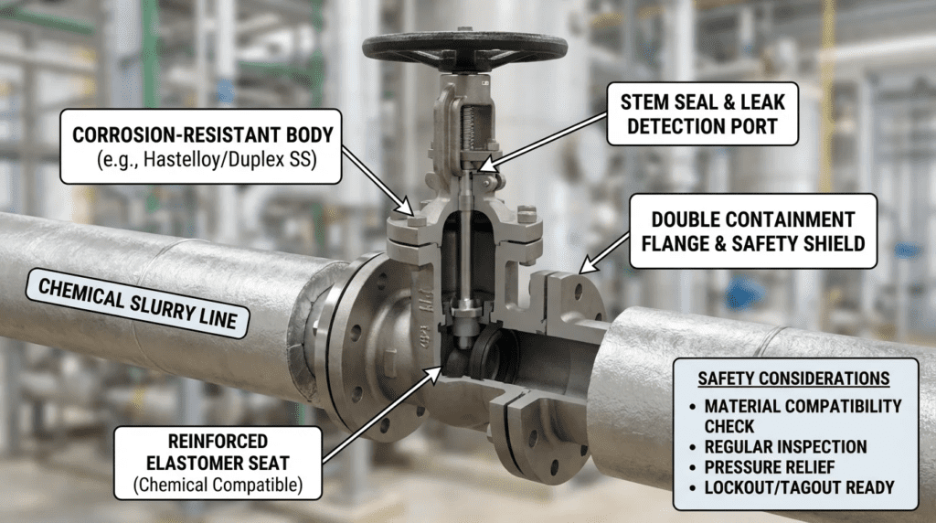
Mud valves—also referred to as flush bottom valves, plug-type sludge valves, or bottom drain valves—are specialized mechanical devices designed to sit flush with the floor of a tank or basin. In municipal water and wastewater treatment, as well as industrial effluent plants, these valves are utilized to evacuate accumulated sediment, precipitant sludge, and degraded chemical slurries from bulk storage, mixing, and settling tanks. Typical applications include draining heavy solids from lime slurry tanks, removing settled impurities from bulk ferric chloride or sodium hypochlorite storage, and evacuating dense polymers or powdered activated carbon (PAC) slurries.
The operating environment for these valves is extraordinarily harsh. They are subjected to the dual threats of chemical attack and mechanical abrasion, all while operating under static liquid head at the most inaccessible point of a tank. A standard cast-iron waterworks mud valve installed in a corrosive chemical application can degrade within weeks, leading to catastrophic loss of containment. Proper selection and specification require a rigorous understanding of fluid rheology, metallurgy, elastomer chemistry, and human factors engineering.
This article provides consulting engineers, utility decision-makers, and plant managers with a comprehensive, unbiased framework for specifying mud valves in chemical service. By focusing strictly on verifiable performance data, material science, and operational realities, this guide will equip professionals to design resilient, safe, and easily maintainable chemical tank drainage systems.
HOW TO SELECT / SPECIFY
Duty Conditions & Operating Envelope
The first step in specifying a mud valve for chemical service is defining the physical operating envelope. Unlike standard isolation valves, mud valves generally operate under low-pressure, gravity-flow conditions dictated by the static head of the fluid in the tank. Engineers must calculate the maximum static pressure (typically less than 20-30 psi for municipal chemical tanks) but account for the specific gravity of the chemical sludge, which can exceed 1.4 for dense slurries.
Operating modes are predominantly intermittent. Mud valves may remain closed for months while sediment accumulates, only to be opened briefly during a tank cleanout or scheduled blowdown. This infrequency of operation creates a high risk of the valve seizing or the chemical crystallizing around the seating surfaces. Temperature parameters must also be defined, accounting for both ambient extremes and exothermic reactions that can occur during chemical dilution (e.g., mixing water with concentrated acids or bases). Future capacity considerations should evaluate whether larger tanks with higher static heads will be retrofitted, requiring heavier valve stems and higher-torque actuation methods.
Materials & Compatibility
When evaluating Mud Valves for Chemical Systems: Compatibility and Safety Considerations must prioritize material science above all other factors. The intersection of corrosion and abrasion rapidly accelerates wear. Relying on generic “stainless steel” is a common specification error.
- Ferric Chloride and Ferric Sulfate: These highly aggressive coagulants will rapidly pit and destroy standard 304 and 316 stainless steels. Mud valves in this service require Titanium, Hastelloy C-276, or heavily lined ductile iron (using ETFE, PFA, or thick PTFE linings).
- Sodium Hypochlorite: While not highly abrasive, off-gassing and alkalinity require specialized plastics or linings. Unplasticized PVC (uPVC), CPVC, or PTFE-lined valves are typical. Elastomers must be Viton (FKM) or PTFE; standard EPDM will rapidly degrade.
- Lime Slurry and Powdered Activated Carbon (PAC): These fluids are highly abrasive. While chemical corrosion is lower, the abrasive wear on seats and plugs is severe. Hard-faced stainless steels (e.g., Stellite overlays), high-chrome alloys, or specially formulated abrasion-resistant polyurethanes are required.
- Polymers: High-molecular-weight polymers can act as adhesives, causing valve plugs to stick to the seats. Non-stick coatings like PTFE or FEP are critical to ensure the valve can be actuated after long periods of closure.
Temperature limits of elastomers must be strictly cross-referenced with chemical concentrations. A gasket material that resists 12.5% sodium hypochlorite at 60°F may fail rapidly if the temperature reaches 90°F during summer storage.
Hydraulics & Process Performance
Mud valves are engineered to minimize flow restriction. A flush-bottom design ensures there are no dead legs or recesses where chemical sediment can bridge, compact, or crystallize. When specifying the valve, engineers must evaluate the Valve Flow Coefficient (Cv) to ensure the required drain time can be met under falling-head conditions.
The hydraulic characteristics of chemical sludges differ significantly from water. Many chemical sludges (like alum or lime) exhibit non-Newtonian, Bingham-plastic behavior, meaning they require a minimum yield stress to initiate flow. If the mud valve is undersized, the static head may not be sufficient to break the yield stress across the restricted orifice, resulting in “rat-holing” or a complete failure to drain. Typically, mud valves for chemical sludges should be sized at least one to two pipe diameters larger than standard liquid drain lines to account for this viscosity.
Installation Environment & Constructability
Mud valves are installed at the lowest elevation of the process system, often requiring operators to access confined spaces or subterranean galleries. The structural configuration of the tank floor must accommodate the valve body, whether it is cast-in-place, flanged to a bottom thimble, or mounted via a spigot.
For deep chemical tanks, manual actuation requires extension stems reaching to an operating floor above the maximum liquid level. Engineers must specify adequate stem guides (typically spaced every 5 to 10 feet depending on stem diameter) to prevent buckling under compressive loads during closure. If the valve is located in a corrosive vapor space (e.g., above a hydrochloric acid tank), the extension stems, floor stands, and fasteners must be constructed of corrosion-resistant alloys or encapsulated in FRP (Fiberglass Reinforced Plastic).
Reliability, Redundancy & Failure Modes
In chemical systems, a leaking mud valve is a reportable environmental incident and a safety emergency. The Mean Time Between Failures (MTBF) for these valves is heavily dependent on the seating mechanism. Common failure modes include:
- Seat Scoring: Abrasive particles get trapped between the plug and the seat during closure, scoring the elastomer or metal surface and causing a continuous leak.
- Stem Galling: Incompatible metal threads on the lifting stem gall under high torque, freezing the valve in position.
- Elastomer Swell: Incorrect chemical compatibility causes the seat O-ring to absorb chemical, swell, and pop out of its retaining groove.
Redundancy is difficult to achieve with a single bottom-drain orifice. Therefore, engineers often specify a double-isolation approach: a flush-bottom mud valve on the tank floor, followed by a secondary isolation valve (like a lined plug or ball valve) immediately downstream on the drain piping. Critical spare parts, including replacement seating rings and stem nuts, must be mandated in the initial procurement specification.
Controls & Automation Interfaces
While many mud valves are manually operated via T-wrenches or handwheels on floor stands, modern automated facilities frequently utilize pneumatic or electric actuators for automated sludge blowdown.
When automating mud valves in chemical service, pneumatic cylinders are often preferred over electric actuators if the environment is highly corrosive or classified as hazardous (explosion-proof). SCADA integration requires discrete limit switches (Open/Closed) to confirm valve status. If an automated mud valve fails to close after a blowdown cycle, the entire tank contents could be lost. Therefore, control strategies must include flow or pressure monitoring on the drain line to trigger emergency alarms if the valve does not report a fully seated position.
Maintainability, Safety & Access
Safety is the paramount concern when handling toxic or corrosive chemicals. Operators must never be forced into a confined space or placed directly beneath a full chemical tank to actuate or repair a valve.
Lockout/Tagout (LOTO) provisions must be inherently designed into the floor stand or actuator. For manual extension stems, locking covers or lockable handwheels are required. Maintenance access must allow for the replacement of the valve’s elastomeric seals without requiring the complete demolition of the tank floor. Some advanced flush-bottom valves feature top-entry designs, allowing the entire plug and seat assembly to be pulled up through the tank via a tether or extended stem once the tank is empty and neutralized.
Lifecycle Cost Drivers
When analyzing total cost of ownership (TCO) for mud valves, Capital Expenditure (CAPEX) represents a fraction of the lifecycle cost. A standard epoxy-coated cast iron mud valve may cost $1,500, while a custom Titanium flush-bottom valve may cost $15,000. However, if the cast iron valve fails in a ferric chloride tank, the ensuing cleanup, regulatory fines, tank downtime, and emergency replacement labor will easily exceed $100,000.
OPEX drivers include the labor required for routine exercising of the valve, periodic replacement of elastomers, and the energy/labor costs associated with neutralizing and draining tanks for unexpected valve maintenance. Specifying premium metallurgy and robust seating mechanisms drastically flattens the TCO curve over a 20-year plant lifecycle.
COMPARISON TABLES
The following tables provide a framework for evaluating different valve configurations and mapping them to specific chemical service environments. Table 1 compares common bottom-drain valve technologies, while Table 2 provides a strict application fit matrix based on fluid characteristics.
| Technology / Type | Key Features | Best-Fit Applications | Limitations & Considerations | Typical Maintenance |
|---|---|---|---|---|
| Rising-Stem Mud Valve (Flush) | Plug lifts vertically into the tank; completely flush with tank floor. | Settling tanks, bulk coagulants, heavy sludge. | Requires extension stem space above tank; susceptible to stem bending if solids fall on it. | Stem lubrication; seat ring replacement (5-10 yrs). |
| Falling-Stem (Disc-lowering) Valve | Disc lowers into the drain pipe to open. | Clean chemicals, applications with limited vertical tank space. | Heavy solids can pack into the recess above the lowered disc, preventing closure. | Clearing debris from recess; packing gland adjustments. |
| Lined Plug Valve (Under-tank) | Quarter-turn operation; fully PTFE/PFA lined body. | Highly corrosive chemicals (Acids, Hypo) without heavy settling solids. | Not flush with tank floor (creates a dead leg); requires access beneath the tank. | Plug adjustment; actuator verification. |
| Pinch Valve (Under-tank) | Full port, elastomer sleeve clamped to close. | Lime slurries, highly abrasive fluids, PAC. | Requires under-tank access; sleeve can rupture if over-pressurized or chemically degraded. | Sleeve replacement (3-7 yrs depending on cycle rate). |
| Chemical / Service | Primary Challenge | Recommended Metallurgy/Lining | Recommended Elastomer | Relative Cost Factor |
|---|---|---|---|---|
| Sodium Hypochlorite (12.5%) | Off-gassing, high alkalinity, attacks metals | PTFE-lined Ductile Iron, uPVC, Titanium | Viton (FKM), PTFE | $$$ |
| Ferric Chloride | Extreme acidic corrosion, aggressive pitting | Titanium, Hastelloy C-276, PFA-lined | PTFE, specialized EPDM | $$$$ |
| Lime Slurry | Severe abrasion, scaling, solids packing | Stellite-faced 316SS, Polyurethane lined | Polyurethane, Natural Rubber | $$ |
| Polymers / Emulsions | High viscosity, adhesion to valve parts | 316SS with non-stick (FEP) coating | Buna-N, EPDM | $$ |
| Alum (Aluminum Sulfate) | Mild acidity, crystallization | 316SS, Alloy 20 | EPDM | $$ |
ENGINEER & OPERATOR FIELD NOTES
Commissioning & Acceptance Testing
Proper commissioning of mud valves dictates their long-term viability. Factory Acceptance Testing (FAT) is highly recommended for alloy and lined valves. Engineers should require a hydrostatic seat leak test conforming to standards such as API 598 or equivalent AWWA requirements. For chemical service, zero visible leakage (drop-tight closure) must be specified.
During the Site Acceptance Test (SAT), the entire extension stem assembly must be verified for alignment. Misalignment of stem guides by even a fraction of an inch will cause eccentric loading on the valve stem, leading to premature packing failure and binding. Operators must perform a “dry pull” of the valve (operating it fully open to fully closed) prior to introducing chemical, measuring the operating torque to establish a baseline. If the initial torque exceeds manufacturer specifications, the installation geometry is flawed and must be corrected immediately.
Common Specification Mistakes
Other frequent errors in bid documents include:
- Under-specifying Wall Thickness: Chemical corrosion allowances must be added to the valve body thickness if unlined metals are used.
- Ambiguous Hardware Requirements: Specifying “stainless steel fasteners” is insufficient. Plated 304SS fasteners will rust in hypochlorite environments; 316SS or B8M class fasteners must be explicitly required.
- Ignoring the “Dead Space”: Selecting a valve that does not sit truly flush with the tank floor, leaving a 2-inch lip where chemical sludge can accumulate and harden, preventing the plug from seating.
O&M Burden & Strategy
To reduce the O&M burden, a rigorous preventive maintenance schedule must be established. Mud valves in chemical service fail most often due to neglect. Because they are designed for intermittent draining, operators may go a year without actuating the valve. During this time, chemical crystallization or sediment compaction locks the plug in place.
Predictive & Preventive Strategy:
- Monthly Exercising: Valves should be “bumped” (opened 10% and immediately closed) monthly to break any chemical scaling on the stem and seats.
- Lubrication: Stem threads and floor stand gearboxes require quarterly lubrication. In corrosive environments, specific chemical-resistant greases (e.g., PFPE or fluorinated lubricants) must be used; standard lithium grease will degrade if exposed to strong oxidizers.
- Visual Inspection: Downstream drain pipes should be equipped with a sight glass or be routed to an observable air gap to visually confirm drop-tight seating.
Troubleshooting Guide
When a mud valve malfunctions in a chemical system, immediate, safe diagnostics are required:
- Symptom: Valve will not fully close (continuous drip).
Root Cause: Debris/crystallization trapped between the plug and seat.
Action: Do not over-torque the handwheel (this will permanently score the seat). Open the valve fully to flush the debris with the static head of the tank, then attempt closure again. - Symptom: Extremely high torque required to operate.
Root Cause: Stem guide misalignment, galling of threaded components, or severe polymer/sludge adhesion.
Action: Inspect all accessible stem guides. Apply penetrating chemical-safe solvent if threads are galled. If the valve is seized, the tank must be bypassed, emptied, and neutralized before mechanical intervention. - Symptom: Chemical pooling around the valve operating stem.
Root Cause: Packing failure or O-ring degradation due to chemical incompatibility.
Action: Tighten packing gland nuts evenly. If leakage persists, the elastomer has degraded and requires complete replacement.
DESIGN DETAILS / CALCULATIONS
Sizing Logic & Methodology
Sizing Mud Valves for Chemical Systems: Compatibility and Safety Considerations is primarily a function of calculating the required tank drawdown time and overcoming the fluid’s yield stress. Engineers cannot simply match the mud valve to the downstream pipe size without verification.
For gravity draining of a tank, Torricelli’s law is adapted to determine the time to drain (t):
t = [A_t / (C_d × A_o × √(2g))] × 2(√(H_1) – √(H_2))
Where:
- A_t = Cross-sectional area of the tank
- C_d = Discharge coefficient of the mud valve (typically 0.60 to 0.80 depending on plug design)
- A_o = Open area of the valve orifice
- g = Acceleration due to gravity
- H_1 = Initial liquid height
- H_2 = Final liquid height
Rule-of-Thumb Limitation: This calculation assumes Newtonian fluid dynamics (like water). Chemical sludges with high solids content (e.g., 5-10% lime slurry) will drain significantly slower. A design safety factor of 1.5 to 2.0 should be applied to the calculated drain time. Furthermore, the downstream piping should maintain a minimum slope of 2% to 3% to ensure the heavy sludge continues to flow by gravity once it passes the valve orifice.
Specification Checklist
A robust engineering specification for a chemical mud valve must include the following critical deliverables:
- Wetted Materials Schedule: Explicit designation of body, plug, seat ring, and stem materials (e.g., Body: Hastelloy C-276; Stem: Titanium Grade 2; Seat: Virgin PTFE).
- Coating Standards: If protective coatings are used (e.g., fusion-bonded epoxy on ductile iron for non-aggressive service), require holiday testing (spark testing) per NACE SP0188 to ensure zero pinhole defects.
- Actuation & Ergonomics: Specify maximum allowable rim pull on manual handwheels (typically 40-50 lbs) to prevent operator injury. If calculated torque exceeds this, a geared floor stand is mandatory.
- Quality Assurance: Require certified Material Test Reports (MTRs) for all alloy components to verify chemical composition before manufacturing.
Standards & Compliance
While there is no single AWWA standard exclusively dedicated to chemical mud valves, engineers must pull compliance criteria from adjacent standards to build a rigorous spec:
- Flange Dimensions: ASME B16.1 or B16.5 for drilling and facing compatibility with tank thimbles.
- Seat Leakage: API 598 or FCI 70-2 (Class VI for soft-seated drop-tight shutoff).
- Plastics and Linings: ASTM D4327 for PTFE lined components; ASTM F441 for CPVC components.
- Actuators: NEMA 4X for corrosive environments; NEMA 7 if located in a classified explosion-proof area (e.g., near methanol or certain polymer storage).
FAQ SECTION
What is a mud valve used for in chemical treatment systems?
In chemical systems, a mud valve is installed at the bottom of a tank to drain accumulated sediment, precipitant sludge, or degraded chemical slurries. They sit flush with the tank floor to ensure complete evacuation of heavy solids without creating “dead legs” where chemicals can crystallize or stagnate.
How do you select the right materials for a chemical mud valve?
Material selection must be based on the specific chemical, its concentration, and maximum operating temperature. For example, ferric chloride requires Titanium or Hastelloy due to aggressive pitting, while sodium hypochlorite requires PTFE-lined bodies or CPVC. Never rely on generic stainless steel without verifying compatibility with the specific chemical sludge.
What is the difference between a mud valve and a standard plug valve?
A true mud valve is designed to be cast or bolted flush into the floor of a tank, lifting its plug vertically into the tank space (or lowering a disc) to allow fluid to drop straight down. A standard plug valve is an inline piping component installed beneath the tank, which creates a vertical “dead leg” of piping between the tank floor and the valve where sludge can harden.
Why do mud valves in chemical tanks fail prematurely?
Premature failure is typically caused by incorrect elastomer selection (causing O-rings to swell and blow out), galvanic corrosion from mismatched stem/body metals, or severe abrasion from slurries like lime. Infrequent operation also leads to chemical crystallization, causing the valve to seize when operators finally attempt to actuate it.
What are the best practices for safety and LOTO with mud valves?
Best practices dictate that operators should never have to enter the tank or a confined space beneath it to actuate the valve. Extension stems to an operating floor above the tank are standard. Lockout/Tagout (LOTO) should be implemented at the operator floor stand via lockable handwheels or locking pin mechanisms to prevent accidental discharge of hazardous chemicals.
How much does a chemical-rated mud valve typically cost?
Costs vary drastically based on metallurgy and size. A 6-inch PTFE-lined or specialized alloy mud valve can range from $5,000 to over $20,000, whereas standard cast-iron valves (unsuitable for harsh chemicals) cost $1,000 to $3,000. The higher CAPEX of chemical-rated valves is offset by preventing catastrophic leaks and eliminating rapid replacement cycles.
CONCLUSION
KEY TAKEAWAYS
- Material Trumps All: Standard cast iron or 316SS will fail rapidly in aggressive chemicals like Ferric Chloride or Sodium Hypochlorite. Specify Titanium, Hastelloy, or heavy PTFE linings.
- Elastomer Precision: Verify gasket and O-ring materials against specific chemical concentrations and temperatures (e.g., Viton for Hypo, EPDM for Alum).
- Sizing for Sludge: Chemical sludges are often non-Newtonian. Apply a 1.5 to 2.0 safety factor to gravity drain-time calculations to overcome fluid yield stress.
- Operator Safety: Mandate extension stems and top-accessible floor stands to keep operators out of confined spaces and away from hazardous chemical spill zones.
- Preventive Maintenance: Valves must be “bumped” (exercised) monthly to prevent chemical crystallization from seizing the stem or seating mechanisms.
Specifying Mud Valves for Chemical Systems: Compatibility and Safety Considerations is a high-stakes engineering task that bridges fluid mechanics, material science, and rigorous safety protocols. The environments at the bottom of chemical settling and storage tanks are among the most unforgiving in any municipal or industrial treatment facility. Engineers must resist the temptation to copy-paste legacy waterworks valve specifications into chemical applications.
By implementing a methodical selection process—starting with exact duty conditions and prioritizing precise metallurgical and elastomeric compatibility—designers can drastically reduce the lifecycle costs of the system. Furthermore, by designing the installation with operator safety and ergonomics in mind, including robust LOTO capabilities and eliminating confined space entry requirements, facilities can protect their personnel from hazardous exposures.
Ultimately, the success of a chemical mud valve relies on a balance of upfront engineering rigor and dedicated operational maintenance. When specialized applications arise—such as highly exothermic reactions, unique proprietary polymer blends, or mixed chemical waste streams—engineers should not hesitate to consult directly with valve metallurgists to verify chemical resistance charts and ensure the specified asset will deliver decades of reliable, safe isolation.