Ball Valves Cavitation and Noise: Causes
INTRODUCTION
Few operational anomalies in a water or wastewater treatment plant are as immediately concerning as the sound of gravel rushing through a pipeline—especially when there is no gravel in the system. For consulting engineers, plant operators, and utility managers, understanding Ball Valves Cavitation and Noise: Causes is a critical step in preventing catastrophic valve failure, excessive piping vibration, and unplanned operational downtime.
A surprising statistic often overlooked during the design phase is that over 60% of premature throttling valve failures in municipal pump stations are linked to improper selection regarding pressure drop and cavitation potential. Standard rotary ball valves are fundamentally “high-recovery” devices. They are excellent for low-friction isolation, but when engineers attempt to use them for flow or pressure control without understanding their hydraulic limitations, the results are predictably destructive.
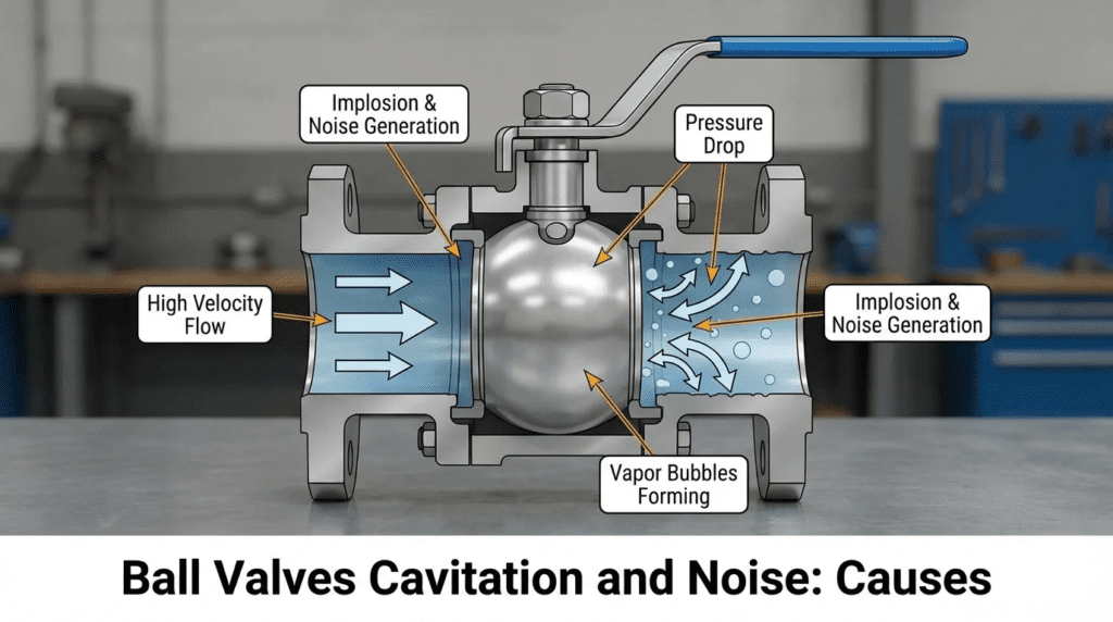
Cavitation occurs when the static pressure of a liquid drops below its vapor pressure as it accelerates through the valve’s restriction (the vena contracta). This causes vapor bubbles to form. As the fluid exits the restriction and slows down, the pressure recovers. If this recovered pressure rises back above the vapor pressure, the vapor bubbles implode violently. These micro-implosions generate localized shockwaves that can exceed 100,000 psi, blasting away hardened stainless steel, eroding valve seats, and generating deafening noise.
In municipal and industrial water, wastewater, and sludge applications, ball valves are frequently utilized due to their high flow capacity, straight-through design, and relative cost-effectiveness. However, specifying the wrong type of ball valve—or miscalculating the hydraulic envelope—leads to severe mechanical degradation. This comprehensive technical guide will help engineers evaluate duty conditions, calculate cavitation risk, and accurately specify ball valves to ensure long-term reliability and process stability.
HOW TO SELECT / SPECIFY
Selecting the proper ball valve for applications prone to high pressure drops requires a rigorous evaluation of the system’s hydraulic envelope and mechanical requirements. The following criteria outline the engineering framework for specifying rotary valves in demanding applications.
Duty Conditions & Operating Envelope
The foundation of preventing cavitation lies in accurately defining the operating envelope. Engineers must clearly specify the maximum, normal, and minimum flow rates alongside their corresponding upstream pressures (P1) and downstream pressures (P2). Cavitation risk is almost always highest at the combination of low flow rates and high pressure differentials (when the valve is operating near the closed position).
Temperature plays a crucial role because it directly dictates the liquid’s vapor pressure (Pv). For example, water at 60°F has a vapor pressure of approximately 0.25 psia, but at 180°F (common in industrial effluent or boiler feed water), the vapor pressure rises to 7.5 psia, significantly shrinking the margin before vaporization occurs.
Operating modes must also be defined. A ball valve used for continuous throttling requires entirely different trim designs than one used for intermittent blowdown or pump start/stop sequencing. Future capacity expansions—often requiring valves to be oversized for current conditions—frequently force valves to operate at 10-20% open, drastically increasing the velocity and the resultant pressure drop at the vena contracta.
Materials & Compatibility
When cavitation cannot be entirely eliminated through process design, material selection becomes the primary defense mechanism against rapid erosion. Standard 316 Stainless Steel is highly susceptible to cavitation damage due to its relative softness. For cavitation-prone services, engineers must specify hardened materials or specialized overlays.
Typical material upgrades include Stellite® 6 overlays on the ball and seat rings, which significantly increase surface hardness and resist the micro-jetting impact of collapsing bubbles. For severe services, such as industrial wastewater with entrained abrasives or high-pressure pump bypass lines, solid Tungsten Carbide or advanced ceramics (like Zirconia or Alumina) may be required.
Chemical compatibility remains paramount; the hardened trims must withstand the corrosive nature of the process fluid. For instance, while Tungsten Carbide offers exceptional abrasion and cavitation resistance, certain cobalt binders used in its manufacture are susceptible to chemical attack from specific coagulants or acids found in water treatment.
Hydraulics & Process Performance: Evaluating Ball Valves Cavitation and Noise: Causes
The hydraulic characteristic most critical to ball valves is the Liquid Pressure Recovery Factor (FL). Standard full-port or reduced-port ball valves have very low FL values (typically 0.55 to 0.65). A low FL indicates that the valve recovers a large percentage of the pressure drop after the vena contracta. High recovery is the primary catalyst for cavitation.
To evaluate performance, engineers must map the valve’s installed flow characteristic curve against the system curve. If the required pressure drop at any operating point exceeds the allowable pressure drop (ΔP allowable), cavitation will occur. If a standard ball valve is specified, the system must maintain sufficient downstream backpressure to suppress the bubble collapse.
When hydraulics indicate severe cavitation, engineers must specify ball valves with anti-cavitation trims. These trims typically feature tortuous paths, multi-stage pressure drops, or slotted/drilled plates inside the ball to break the large pressure drop into several smaller, safe pressure drops, thereby keeping the vena contracta pressure above the vapor pressure.
Installation Environment & Constructability
The physical installation environment drastically affects the longevity of a cavitating or noisy valve. Ball valves installed with insufficient straight pipe runs upstream and downstream will suffer from turbulent flow regimes that exacerbate localized pressure drops. A general rule of thumb is a minimum of 5 pipe diameters upstream and 10 pipe diameters downstream, though specific OEM recommendations and ISA standards should govern.
Because cavitation causes severe high-frequency vibration, structural piping supports must be rigorously designed. Thin-wall piping (e.g., Schedule 10) will amplify hydrodynamic noise and is more prone to fatigue failure from vibration. Specify heavier wall piping (Schedule 40 or 80) immediately downstream of valves in high-pressure-drop services.
Constructability considerations must also include access to the valve for inevitable maintenance. Heavy anti-cavitation ball valves, particularly trunnion-mounted designs, require adequate lifting clearances and structural support independent of the pipe.
Reliability, Redundancy & Failure Modes
The Mean Time Between Failures (MTBF) for a ball valve in a cavitating service can be measured in weeks if improperly specified, compared to decades in a benign isolation service. The most common failure modes include seat ring erosion (leading to loss of shutoff capability), ball surface pitting (which tears up soft seats upon subsequent actuation), and stem/packing leaks caused by excessive vibration.
For critical infrastructure, such as high-service pump discharge control or reservoir level control, redundancy is mandatory. N+1 configurations allow for maintenance without halting plant production. When analyzing reliability data, engineers must distinguish between theoretical Cv limits and practical, continuous-duty operating limits.
Critical spare parts requirements should be written into the specification. For throttling ball valves, this typically includes a complete set of seats, seals, packing, and potentially a replacement characterized ball/trim set.
Controls & Automation Interfaces
Controlling a ball valve near its closed position—where cavitation is most severe—requires precise automation. Rotary ball valves exhibit a distinct “deadband” and hysteresis, resulting from mechanical slop in the actuator-to-stem linkage. If the control loop requires the valve to make small adjustments in a cavitating region, poor linkage will cause the valve to hunt, exacerbating wear.
Specifications must demand rigid mounting brackets, oversized stems, and high-resolution smart positioners. For SCADA integration, 4-20mA signals with HART protocol are standard, but advanced diagnostics capable of monitoring valve signature curves, friction, and breakaway torque provide predictive maintenance data to operators.
Control strategies should be programmed to prevent the valve from operating below its minimum controllable Cv or above a specific differential pressure threshold, utilizing automation to enforce the mechanical operating envelope.
Maintainability, Safety & Access
When high noise and cavitation are present, safety becomes a significant factor. Aerodynamic and hydrodynamic noise can easily exceed OSHA’s 85 dBA threshold for an 8-hour exposure limit. If acoustic insulation or source-treatment (anti-cavitation trim) cannot reduce the noise, the space must be designated as a high-noise area, requiring specialized operator PPE.
Maintainability hinges on the valve’s architectural design. Top-entry ball valves allow for in-line trim replacement without removing the heavy valve body from the pipeline, significantly reducing labor hours. Split-body (two-piece or three-piece) valves are less expensive initially but require full removal from the line, necessitating pipe spool removal and heavy lifting equipment.
Lockout/tagout (LOTO) provisions must be robust, considering the high-pressure nature of these installations. Actuators should feature mechanical lockouts and handwheels for manual override during power or pneumatic failures.
Lifecycle Cost Drivers
The Capital Expenditure (CAPEX) for a standard floating ball valve is vastly lower than that of a severe-service, multi-stage trunnion ball valve or a V-port valve with noise attenuation trim. However, prioritizing CAPEX over Operational Expenditure (OPEX) in a high-pressure-drop application is a classic engineering misstep.
The Total Cost of Ownership (TCO) must account for the rapid degradation of incorrectly specified equipment. A cavitating standard ball valve may require replacement every 12 months, incurring costs for the replacement valve, labor, crane rentals, and plant downtime. Over a 10-year lifecycle, a severely engineered, anti-cavitation ball valve that costs 400% more upfront will typically save tens of thousands of dollars.
COMPARISON TABLES
The following tables provide an unbiased engineering comparison to assist in technology selection and application matching. Use Table 1 to evaluate different rotary and linear valve technologies when throttling and cavitation are a concern. Use Table 2 to determine the best-fit technology based on specific application constraints.
Table 1: Valve Technology Comparison for Throttling and High-Drop Services
| Technology / Type | Features & Hydraulic Profile | Best-Fit Applications | Limitations regarding Cavitation/Noise | Typical Maintenance |
|---|---|---|---|---|
| Standard Full/Reduced Port Ball | High capacity, low FL (~0.60), rotary motion. High pressure recovery. | On/Off isolation, very low pressure drop modulation. | Highly prone to cavitation if throttled. Poor rangeability. High noise generation. | Replace soft seats and stem packing every 5-7 years in clean service. |
| Segmented V-Port Ball | Characterized V-notch, higher FL (~0.70-0.75), excellent rangeability. | Flow control of slurries, wastewater, and pulp. Moderate pressure drops. | Better than standard ball, but will still cavitate at high ΔP. Noise can still exceed 85 dBA. | Seat replacement, actuator linkage calibration, bearing inspection. |
| Anti-Cavitation Trim Ball Valve | Internal slotted plates or tortuous paths. Very high FL (>0.90). | Pump discharge control, high-head reservoir feed, severe service throttling. | High CAPEX. Prone to clogging if fluid contains large solids or fibrous rags. | Periodic cleaning of trim passages. Trim replacement requires heavy lifting. |
| Rotary Eccentric Plug | Offset plug, moderate FL (~0.75-0.80), rugged construction. | Raw sewage throttling, sludge control, moderate ΔP applications. | Offers moderate cavitation resistance but lacks the multi-stage drop needed for severe service. | Plug facing replacement, shaft packing adjustment. |
Table 2: Application Fit Matrix
| Application Scenario | Fluid Type | Pressure Drop Ratio (ΔP / P1) | Recommended Valve Technology | Relative Cost |
|---|---|---|---|---|
| Pump Isolation / Header Block | Potable Water | < 0.1 (Low) | Standard Full-Port Ball Valve | $ |
| Level Control (Gravity Fed) | Treated Effluent | 0.1 to 0.3 (Moderate) | Segmented V-Port Ball Valve | $$ |
| High-Head Pump Bypass / Recirculation | Raw Water | > 0.5 (High/Severe) | Anti-Cavitation Trim Ball Valve | $$$$ |
| Sludge Flow Control | Primary/WAS Sludge | 0.2 to 0.4 (Moderate) | Rotary Eccentric Plug / Hardened V-Port | $$$ |
ENGINEER & OPERATOR FIELD NOTES
Translating theoretical specifications into real-world plant performance requires meticulous attention during testing, installation, and daily operation. The following field notes bridge the gap between design engineering and plant operations.
Commissioning & Acceptance Testing
Rigorous Factory Acceptance Testing (FAT) is essential for any severely characterized ball valve. For valves destined for high-pressure-drop applications, the FAT must include a hydrostatic shell test, a seat leakage test per ANSI/FCI 70-2 (typically Class IV or V, depending on the need for tight shutoff), and a full stroke timing test with the installed actuator and positioner.
During the Site Acceptance Test (SAT), engineers must verify the valve’s performance under actual process conditions. This is the moment to establish baseline acoustic profiles. Operators should use ultrasonic acoustic monitors or simple decibel meters to record baseline noise levels at varying valve positions (e.g., 20%, 50%, 80% open). An SAT punch list should strictly evaluate positioner calibration, ensuring the valve physically achieves the commanded SCADA position without hunting or oscillation.
Common Specification Mistakes
One of the most frequent errors found in engineering bid documents is specifying line-sized standard ball valves for control applications. Engineers often size the pipe for an optimal velocity (e.g., 5-7 ft/sec), resulting in a 12-inch pipe. They then specify a 12-inch full-port ball valve for flow control. In operation, a 12-inch full-port valve will likely need to operate at 5-15% open to generate the necessary pressure drop, instantly plunging the vena contracta into severe cavitation.
Another common mistake is ambiguous language regarding noise limits. Simply stating “valve shall not be noisy” is unenforceable. Specifications must dictate a measurable limit, such as: “Hydrodynamic noise shall not exceed 85 dBA, measured 1 meter downstream and 1 meter away from the pipe wall, under all specified operating conditions, calculated per IEC 60534-8-4.”
O&M Burden & Strategy
Preventive maintenance for high-performance rotary valves requires a shift from time-based maintenance to condition-based monitoring. Routine inspections (monthly) should involve walking the line and listening for acoustic changes. The physical O&M burden involves periodic greasing of trunnion bearings and inspecting the linkage between the actuator and stem for mechanical wear (slop).
Labor hour estimates for a complete trim replacement on a top-entry anti-cavitation ball valve (e.g., 8-inch size) typically range from 8 to 12 labor hours for a two-person crew, provided the valve does not need to be cut out of the pipeline. If the valve is a standard split-body that requires line removal, estimate 24-32 labor hours factoring in rigging, spool removal, and flange alignment.
Troubleshooting Guide: Identifying Ball Valves Cavitation and Noise: Causes
When an operator reports a noisy valve, precise diagnostics are required to determine the root cause before attempting a fix.
- Symptom: Sound of gravel or popping inside the pipe.
- Root Cause: Hydrodynamic Cavitation. Fluid is vaporizing and imploding.
- Diagnostic: Temporarily increase downstream backpressure (e.g., throttle a downstream manual valve) to see if the noise stops. If it does, cavitation is confirmed.
- Fix: Permanent solution requires replacing the valve with an anti-cavitation trim or installing an engineered backpressure orifice plate downstream.
- Symptom: High-pitched whistling or roaring.
- Root Cause: Aerodynamic noise or Choked Flow. Gas/air velocity has reached Mach 1 at the vena contracta.
- Diagnostic: Check flow rates against sonic velocity limits.
- Fix: Source-treatment with low-noise trim (drilled plates) or path-treatment via acoustic pipe insulation.
- Symptom: Valve position is hunting/oscillating.
- Root Cause: Oversized valve operating too close to the seat, or worn actuator linkage.
- Diagnostic: Check SCADA commanded vs. actual position feedback. Manually lock the valve position; if flow stabilizes, the issue is control loop tuning or mechanical deadband.
DESIGN DETAILS / CALCULATIONS
Accurate sizing and calculation of the cavitation index are mandatory steps in mitigating destructive forces. Engineers must rely on empirical formulas established by industry standards rather than rules-of-thumb.
Sizing Logic & Methodology
To evaluate a ball valve for cavitation, engineers must calculate the Cavitation Index ($sigma$). While various definitions exist, the Instrument Society of America (ISA) often utilizes the following simplified ratio for assessing cavitation potential:
$sigma = (P1 – Pv) / Delta P$
Where:
- P1 = Upstream absolute pressure (psia)
- Pv = Vapor pressure of the liquid at flowing temperature (psia)
- $Delta P$ = Actual pressure drop across the valve (P1 – P2) (psi)
Interpretation of the Cavitation Index for Standard Ball Valves:
- $sigma > 2.0$: Safe operating zone. Cavitation is unlikely.
- $1.5 < sigma < 2.0$: Incipient cavitation. Mild noise, minor pitting possible over long durations.
- $1.0 < sigma < 1.5$: Severe cavitation. Loud noise, rapid mechanical damage to standard trims.
- $sigma < 1.0$: Flashing or choked flow.
To determine if the fluid will actually drop below its vapor pressure at the vena contracta, engineers must calculate the Allowable Pressure Drop ($Delta P allowable$) using the Liquid Pressure Recovery Factor (FL):
$Delta P allowable = FL^2 times (P1 – Ff times Pv)$
(Where Ff is the liquid critical pressure ratio factor, typically 0.96 for water under 200°F).
If the actual system $Delta P$ exceeds the $Delta P allowable$, the fluid will vaporize, and since it is a liquid system, it will likely cavitate upon recovery. Because standard ball valves have an FL of roughly 0.60, their allowable pressure drop is exceptionally small compared to globe valves (FL ~ 0.90).
Specification Checklist
To properly specify a ball valve for modulating service, ensure the following items are explicitly detailed in the procurement documents:
- Valve Type: Specific designation (e.g., Segmented V-Port, Top-Entry Anti-Cavitation Trunnion).
- Process Data: P1, P2, Flow Rate (Min/Normal/Max), Specific Gravity, Vapor Pressure.
- Performance Limits: Maximum allowable hydrodynamic noise (e.g., 85 dBA).
- Trim Material: Minimum hardness requirements (e.g., Stellite 6, minimum 38 HRC, or solid Tungsten Carbide).
- Actuation: Fail position, required safety factors for breakaway torque (typically 1.5x minimum), and smart positioner protocol.
- Testing: Required factory tests, specifically calling out ISA 75.23 for cavitation evaluation if applicable.
Standards & Compliance
Engineering designs must reference relevant codes to ensure compliance and safety. For control valves and cavitation, the primary standards are:
- ISA 75.01.01: Flow Equations for Sizing Control Valves. (The definitive standard for calculating Cv, choked flow, and $Delta P allowable$).
- ISA 75.23: Considerations for Evaluating Control Valve Cavitation.
- IEC 60534-8-4: Prediction of noise generated by hydrodynamic flow.
- AWWA C507: Standard for Ball Valves, 6 In. Through 60 In. (Though primarily focused on isolation, it dictates structural and material minimums for municipal water).
- FCI 70-2: Control Valve Seat Leakage standard.
FAQ SECTION
What are the primary Ball Valves Cavitation and Noise: Causes?
The primary causes are forcing a high-recovery valve (like a standard ball valve) to take a large pressure drop, causing the static pressure at the vena contracta to dip below the fluid’s vapor pressure. The subsequent recovery of pressure causes vapor bubbles to collapse violently. This collapse generates shockwaves and micro-jets that create the “gravel” noise and mechanically erode the valve internals.
How do you calculate if a ball valve will cavitate?
Engineers calculate the Cavitation Index ($sigma = (P1 – Pv) / Delta P$) and the Allowable Pressure Drop ($Delta P allowable = FL^2 times (P1 – Ff times Pv)$). If the actual system pressure drop is greater than the allowable pressure drop, cavitation will occur. You must know the valve’s Liquid Pressure Recovery Factor (FL) to perform this calculation. See the [[Sizing Logic & Methodology]] section for formula details.
Can segmented V-port ball valves prevent cavitation?
V-port ball valves are better for throttling than standard full-port ball valves because their characterized notch provides better flow resolution and a slightly higher FL (recovery factor). However, they cannot prevent cavitation in severe pressure-drop applications. They only slightly delay the onset compared to standard ball valves. For high drops, specialized anti-cavitation multi-stage trims are required.
What is the difference between flashing and cavitation in a control valve?
Cavitation occurs when pressure drops below vapor pressure and then recovers above it, causing bubbles to collapse. Flashing occurs when the pressure drops below vapor pressure and stays below it downstream. Flashing creates a high-velocity vapor/liquid mixture that causes smooth, sandblasted-looking erosion, whereas cavitation causes rough, pitted, sponge-like damage.
How do you mitigate hydrodynamic noise in a ball valve?
Hydrodynamic noise is a direct byproduct of cavitation and turbulence. To mitigate it, you must treat the source by installing a valve with anti-cavitation trim (which utilizes multi-stage pressure drops to prevent bubble formation) or alter the system dynamics by increasing downstream backpressure. Path treatments, like heavy acoustic pipe insulation or thicker pipe walls, only mask the noise but do not stop the mechanical damage.
What is the typical lifespan of a ball valve in cavitating service?
An improperly specified standard ball valve in severe cavitating service can fail in weeks to months, typically suffering from seat destruction and loss of isolation capability. A properly specified anti-cavitation ball valve with hardened trims (like Stellite or Tungsten Carbide) can operate reliably for 10 to 15 years before requiring trim replacement, making the higher CAPEX a better lifecycle investment.
CONCLUSION
KEY TAKEAWAYS
- Cavitation is a hydraulic reality, not a mechanical defect: It occurs when static pressure drops below vapor pressure at the vena contracta and recovers downstream.
- Standard ball valves are high-recovery devices: Their low Liquid Pressure Recovery Factor (FL ~0.60) makes them highly susceptible to cavitation if used for high-pressure throttling.
- Always calculate the Cavitation Index ($sigma$): If $sigma$ approaches 1.5 or lower, standard valves will suffer damage; engineered trims are required.
- Differentiate between Flashing and Cavitation: Anti-cavitation trims do not solve flashing. System pressure profiles must be fully understood.
- Invest in OPEX protection: A valve with severe-service anti-cavitation trim has a higher CAPEX but drastically reduces TCO by preventing rapid mechanical failure and pipe rupture.
Specifying equipment for municipal and industrial water systems requires a meticulous understanding of process dynamics. When addressing Ball Valves Cavitation and Noise: Causes, engineers and operators must recognize that a valve is only as good as its hydraulic fit within the system. Utilizing a standard isolation ball valve to perform the duty of a characterized control valve inevitably results in rapid mechanical degradation, high-frequency vibration, and intolerable noise levels.
The decision framework for selecting the right valve demands a sequence of precise calculations. Engineers must first identify the operating extremes—maximum pressure drops at minimum flows—and calculate the Allowable Pressure Drop based on the fluid’s vapor pressure. If the required drop exceeds the allowable limits of a standard or V-port ball valve, the specification must pivot to specialized technologies featuring multi-stage, anti-cavitation trims, or hardened materials like Tungsten Carbide.
Ultimately, balancing competing requirements—such as initial capital constraints versus long-term operability—is the core responsibility of the design engineer. By integrating stringent ISA sizing methodologies, demanding rigorous FAT/SAT testing, and equipping operators with condition-based monitoring strategies, utilities can successfully mitigate the destructive forces of cavitation, ensuring safe, quiet, and reliable plant operations for decades.