Anti-Cavitation Cavitation and Noise: Causes
Introduction
For municipal and industrial engineers, few phenomena are as destructive or as misunderstood as cavitation. Often described by operators as the sound of “pumping marbles” or “gravel passing through the pipe,” cavitation represents a violent phase change in fluid dynamics that creates shockwaves capable of eroding hardened steel, destroying mechanical seals, and causing catastrophic failure in pumps and control valves. Despite its prevalence, specifications often fail to adequately address the full spectrum of Anti-Cavitation Cavitation and Noise: Causes, leading to premature equipment retirement and inflated operational expenditures (OPEX).
In water and wastewater treatment plants, cavitation is not merely a nuisance; it is a direct threat to process reliability. It occurs in high-service pumps, return activated sludge (RAS) systems, and pressure reducing valve (PRV) stations. According to industry reliability data, hydraulic instability—of which cavitation is a primary driver—accounts for approximately 30% of all pump failures. Furthermore, the noise generated by cavitation often exceeds OSHA limits, creating safety hazards for plant personnel.
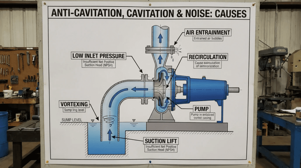
Many engineers overlook the fact that cavitation is not a single phenomenon but a collection of distinct failure modes, including classic suction cavitation, discharge recirculation, and air entrainment (pseudo-cavitation). A specification that treats all noise and vibration as identical will fail to resolve the root cause. This article provides a deep technical analysis of Anti-Cavitation Cavitation and Noise: Causes, equipping design engineers and plant directors with the specific criteria needed to select robust equipment, design proper suction piping, and implement effective control strategies.
How to Select / Specify
Selecting equipment to resist or avoid cavitation requires a holistic view of the system curve, the equipment’s operating envelope, and the fluid properties. The goal is to maximize the margin between the Net Positive Suction Head Available (NPSHa) and the Net Positive Suction Head Required (NPSHr), while also selecting materials and geometries that can withstand incidental cavitation events.
Duty Conditions & Operating Envelope
The first line of defense against cavitation is accurate hydraulic modeling. Engineers must evaluate the system not just at the Best Efficiency Point (BEP), but across the entire operating range.
- NPSH Margin: A standard specification requiring NPSHa > NPSHr is often insufficient. For high-energy pumps or wastewater applications with entrained gases, a margin of 1.3 to 1.5 times the NPSHr (or a minimum of 5 feet/1.5 meters differential) is recommended to prevent incipient cavitation.
- Flow Rate Variability: Cavitation often occurs when pumps operate too far to the left (suction recirculation) or right (classic cavitation) of the BEP. Specifications should require the manufacturer to define the Preferred Operating Region (POR) and the Allowable Operating Region (AOR).
- Temperature Effects: Vapor pressure rises with temperature. While municipal water is typically cool, industrial wastewater or scrubber effluent can operate at elevated temperatures, drastically reducing NPSHa. The specification must explicitly state the maximum fluid temperature for NPSH calculations.
- Valve Pressure Drop: For control valves, calculate the cavitation index (Sigma, σ). If σ indicates severe cavitation potential, the specification must call for anti-cavitation trim rather than standard cages.
Materials & Compatibility
When hydraulic conditions make cavitation unavoidable (or when margins are tight), material selection becomes the critical safeguard. The damage mechanism in cavitation is mechanical fatigue caused by micro-jet implosions, not chemical corrosion.
- Hardness vs. Toughness: Materials with high tensile strength and hardness generally resist cavitation erosion better. For example, CD4MCu (Duplex Stainless Steel) offers significantly higher cavitation resistance than Cast Iron (ASTM A48) or Bronze.
- Impeller Materials: In wastewater applications, specifying 316 Stainless Steel or High-Chrome Iron impellers is a standard anti-cavitation strategy. These materials have a tighter grain structure that resists the pitting action of bubble collapse.
- Valve Trim: For high-pressure-drop valves, specifications should mandate hardened trim materials, such as Stellite facing or 17-4 PH stainless steel, to prevent wire-drawing and erosion of the seating surfaces.
Hydraulics & Process Performance
The hydraulic design of the impeller and volute (or valve body) dictates the onset of cavitation.
- Suction Specific Speed ($N_{ss}$): This dimensionless number indexes the impeller’s suction capabilities. While high $N_{ss}$ (above 11,000 U.S. units) implies low NPSHr, it often narrows the stable operating window, making the pump more prone to recirculation cavitation at partial loads. A conservative specification often limits $N_{ss}$ to between 8,500 and 10,000 for maximum reliability.
- Valve Recovery Coefficient ($F_L$): In control valves, a high recovery coefficient indicates that pressure recovers significantly after the vena contracta, increasing the risk of vapor pressure violation. Engineers should specify “Low Recovery” or “Anti-Cavitation” valves (such as multi-path or labyrinth trim) for high-differential pressure applications.
- Air Handling: In wastewater, entrained air can dampen cavitation noise but ruin efficiency. Impellers designed with large eye areas can handle two-phase flow better but may require higher NPSH.
Installation Environment & Constructability
Poor installation is a leading cause of Anti-Cavitation Cavitation and Noise: Causes regardless of pump quality. Turbulence at the suction eye creates localized low-pressure zones where vapor bubbles form.
- Suction Piping Geometry: The Hydraulic Institute (HI) Standards recommend a straight run of pipe equivalent to 5-10 pipe diameters (D) upstream of the pump suction. Elbows, strainers, or valves placed too close to the inlet distort the velocity profile.
- Submergence: In wet well applications, insufficient submergence leads to vortexing and air entrainment. Specifications must define the minimum submergence level based on flow rate and bell diameter (ANSI/HI 9.8).
- Elevation: Minimizing the static lift is the most effective way to increase NPSHa. Where possible, specify flooded suction configurations for critical pumps.
Reliability, Redundancy & Failure Modes
Engineering for reliability involves acknowledging that pumps may occasionally operate in cavitation zones during transient events (e.g., valve switching, line filling).
- Vibration Monitoring: Specify continuous vibration monitoring (accelerometers) on bearing housings. Cavitation generates high-frequency broadband energy. Modern reliability systems can detect the specific spectral signature of cavitation versus misalignment.
- Bearing Life: Cavitation causes axial shuttling and radial loads that drastically reduce bearing L10 life. Specify heavy-duty bearing frames with L10h life exceeding 50,000 or 100,000 hours to absorb these transient loads.
- Seal Plans: Mechanical seals are often the first component to fail during cavitation due to face vaporization. API Plan 53 or 54 (pressurized barrier fluid) can protect seals even if the process fluid vaporizes.
Controls & Automation Interfaces
Modern Variable Frequency Drives (VFDs) and SCADA systems are powerful tools for anti-cavitation control.
- NPSHa Monitoring: Advanced control strategies calculate real-time NPSHa using suction pressure transmitters and temperature sensors. If NPSHa approaches the critical limit, the PLC can trim pump speed (reducing NPSHr) or throttle a discharge valve.
- Minimum Flow Protection: To prevent thermal cavitation and suction recirculation, specify automatic recirculation valves (ARVs) or flow-paced control loops that ensure the pump never operates below its minimum continuous stable flow (MCSF).
- Valve Sequencing: Program slow ramp rates for control valves to prevent water hammer and transient pressure drops that trigger cavitation.
Maintainability, Safety & Access
When cavitation damage does occur, the design must facilitate rapid repair.
- Replaceable Wear Components: Specify pumps with replaceable wear rings on both the suction and discharge sides of the impeller. For valves, specify “quick-change” trim that does not require removing the valve body from the line.
- Inspection Ports: For large pumps (>100 HP), inspection ports on the suction side allow operators to visually inspect the impeller eye for cavitation pitting without dismantling the unit.
- Noise Attenuation: Since cavitation noise can exceed 100 dBA, specify sound-attenuating enclosures or insulation lagging for equipment where cavitation cannot be completely eliminated by design (e.g., massive energy dissipation valves).
Lifecycle Cost Drivers
The cost of ignoring cavitation is far higher than the premium for anti-cavitation equipment.
- Energy Penalty: Cavitation disturbs the flow path, causing a drop in hydraulic efficiency (drop in the H-Q curve). A pump operating in cavitation may consume 10-15% more power for the same delivered flow.
- Component Replacement: A standard cast iron impeller in a cavitating slurry pump may last 6 months. A high-chrome or CD4MCu impeller, properly selected, may last 5-10 years.
- Downtime: The total cost of ownership (TCO) calculation must account for the cost of emergency maintenance and potential regulatory fines for permit violations if critical pumping redundancy is lost.
Comparison Tables
The following tables provide a structured comparison to assist engineers in selecting the correct technology for mitigation. Table 1 focuses on valve trim technologies used to combat cavitation noise and damage. Table 2 outlines the different types of pump cavitation, assisting in root cause analysis.
| Technology Type | Mechanism of Action | Best-Fit Applications | Limitations/Considerations | Maintenance Profile |
|---|---|---|---|---|
| Standard Cage Trim | Single-stage pressure drop across a cage window. | Low differential pressure; Clean water; Non-critical isolation. | High recovery ($F_L$); Prone to cavitation at high $Delta P$; Loud noise generation. | Moderate; trim damage common if misapplied. |
| Multi-Stage / Labyrinth Trim | Divides pressure drop into multiple small steps, keeping fluid above vapor pressure. | High-pressure pump bypass; Reservoir fill valves; Severe service pressure reduction. | High initial cost; Susceptible to clogging with solids/debris (requires fine screening). | Low; designed for long life in severe duty. |
| Drilled Hole / Anti-Cavitation Cage | Shifts frequency of noise to higher spectrum; collision of jets in center of cage. | Moderate pressure drops; Wastewater with minor solids. | Limited $Delta P$ capability compared to labyrinth; High noise still possible. | Moderate; cage erosion is the primary failure mode. |
| Rotary Control (V-Port Ball/Plug) | Shearing action; high recovery but straight-through flow path. | Sludge; Raw sewage; Applications with high solids content. | Difficult to eliminate cavitation completely in high $Delta P$; requires hardened facings. | Moderate to High; seats wear in abrasive/cavitating service. |
| Plunger / Needle Valves | Linear movement regulates annular flow area; guides flow to center. | Flow control at dam outlets; Large transmission mains; Discharge to atmosphere. | Large physical footprint; Complex actuator mechanics. | Low; extremely robust but requires specialized service. |
| Cavitation Type | Primary Symptoms | Operating Condition | Typical Root Cause | Corrective Action |
|---|---|---|---|---|
| Classic (Suction) Cavitation | “Marbles” noise; Pitting on the suction side (visible) of impeller vanes. | High Flow / Low Head (Right of BEP). | NPSHa < NPSHr; Clogged suction strainer; High fluid temp. | Increase suction level; Reduce friction loss; Lower pump speed (VFD). |
| Suction Recirculation | Loud cracking noise at suction; Pitting on the pressure side (hidden) of vanes. | Low Flow (Left of BEP). | Oversized pump; Operating below Minimum Continuous Stable Flow (MCSF). | Install bypass line; Change impeller design; Verify $N_{ss}$ selection. |
| Discharge Recirculation | Noise at discharge volute; Damage to impeller vane tips/cutwater. | Very Low Flow (Shut-off head approach). | Closed discharge valve; Excessive gap between impeller and volute (gap “A”). | Open discharge valve; Check wear ring clearance; Machine impeller OD. |
| Air Entrainment | Intermittent noise; Reduced flow; Vibration spikes. | Variable. | Vortexing in wet well; Leaking suction pipe gaskets; Aeration in process. | Increase submergence; Install vortex breaker; Seal suction flange leaks. |
Engineer & Operator Field Notes
Designing for anti-cavitation is theoretical; managing it in the field is practical. The following sections outline best practices for commissioning, maintenance, and troubleshooting regarding Anti-Cavitation Cavitation and Noise: Causes.
Commissioning & Acceptance Testing
The Factory Acceptance Test (FAT) and Site Acceptance Test (SAT) are the best opportunities to verify anti-cavitation performance.
- NPSH Testing: For critical pumps, require an NPSH test (HI 14.6) during the FAT. Witness the test to confirm the pump performs stably at the specified NPSHa + Margin. Do not accept extrapolation from smaller models.
- Vibration Baseline: During SAT, establish a vibration baseline across the full flow range. Note any spike in vibration amplitudes at specific frequencies (vane pass frequency vs. broadband noise). This baseline is crucial for future predictive maintenance.
- Valve Signature: For control valves, perform a step-response test. Listen for the distinct crackling sound of cavitation as the valve modulates through high-pressure-drop positions. If audible, verify if the noise level matches the specification (usually < 85 dBA).
Common Specification Mistakes
Engineers often inadvertently induce cavitation through vague or conflicting specifications.
- “Runout” Requirements: Specifying that a pump must operate at “runout” (far right of curve) without cavitation often forces manufacturers to select oversized pumps with high Suction Specific Speed impellers. These pumps then suffer from recirculation cavitation at normal operating points.
- Ignoring Static Head Variations: In wastewater wet wells, the static head changes constantly. Specifying a pump based only on the “average” water level can lead to severe suction cavitation when the well is pumped down to the “pump off” setpoint.
- Oversizing Control Valves: A valve sized for future peak flows often operates at 10-20% opening today. At low openings, velocity is high, and the risk of cavitation increases. Use characterized trim or multiple smaller valves in parallel.
O&M Burden & Strategy
Operational strategies can mitigate the effects of existing cavitation issues.
- Impeller Inspections: Schedule annual internal inspections. Look for “sponge-like” appearance on the impeller vanes.
- Leading Edge Pitting: Indicates Classic Suction Cavitation.
- Trailing Edge/Pressure Side Pitting: Indicates Recirculation Cavitation.
- Wear Ring Maintenance: As wear ring clearances open up (double the new clearance), internal recirculation increases, which disturbs the flow into the impeller eye and effectively increases NPSHr. Maintain tight clearances to preserve suction performance.
- Predictive Maintenance (PdM): Utilize ultrasound testing. Cavitation produces high-frequency ultrasonic emissions long before audible noise or vibration damage occurs. This allows operators to adjust setpoints (e.g., raise tank levels) before damage sets in.
Troubleshooting Guide
Test: Throttle the discharge valve. If the noise decreases or stops, it is likely Classic Cavitation (because you reduced flow and required NPSH). If the noise remains or gets worse (due to turbulence), it might be Air Entrainment or Recirculation.
- Check Suction Pressure: Install a compound gauge on the suction flange. Compare the reading to the vapor pressure of the fluid. Remember to correct for gauge elevation relative to the pump centerline.
- Listen to the Pipe: Use a mechanic’s stethoscope. Cavitation noise is often loudest at the suction eye or the valve seat. Mechanical noise (bearings) is loudest at the housing.
- Review VFD Logs: Check if failures correlate with specific speeds or flow rates. Cavitation is often specific to a flow regime.
Design Details / Calculations
To scientifically prevent Anti-Cavitation Cavitation and Noise: Causes, engineers must master the sizing logic and compliance standards.
Sizing Logic & Methodology
The fundamental equation for avoiding cavitation is:
NPSHa ≥ NPSHr + Margin
Where:
- NPSHa = $H_{atm} + H_{static} – H_{friction} – H_{vapor}$
- $H_{atm}$: Atmospheric pressure (adjusted for altitude). High-altitude plants have significantly lower NPSHa.
- $H_{static}$: Elevation difference between fluid surface and pump centerline (negative for suction lift).
- $H_{friction}$: Losses in suction piping, valves, and strainers.
- $H_{vapor}$: Vapor pressure of the liquid at operating temperature.
Step-by-Step Sizing Approach:
- Determine Worst-Case Scenario: Calculate NPSHa at the lowest expected wet well level, highest fluid temperature, and maximum flow rate (highest friction loss).
- Select Margin: Apply a safety margin. HI 9.6.1 suggests margins based on pump energy levels.
- Standard Water Pumps: 1.1 ratio or +2 ft.
- Wastewater/Sludge: 1.3 ratio or +5 ft (to account for gas content).
- Check Valve Sigma ($sigma$): For valves, $sigma = (P_1 – P_v) / (P_1 – P_2)$.
- $sigma > 2.0$: Generally safe.
- $1.0 < sigma < 2.0$: Incipient cavitation possible; use hard trim.
- $sigma < 1.0$: Severe cavitation; requires multi-stage anti-cavitation trim.
Specification Checklist
Ensure these items appear in your Section 11 (Equipment) or Section 40 (Process) specifications:
- [ ] NPSH Curve: Manufacturer must supply NPSH3 curve based on test data, not calculation.
- [ ] Material Hardness: Impellers/Trim must meet minimum Brinell hardness if cavitation risk is identified.
- [ ] Suction Piping: Drawings must show straight pipe lengths meeting HI standards; avoid reducing elbows directly at pump flanges.
- [ ] Vibration Limits: Specify ISO 10816-7 Category I or II limits.
- [ ] Documentation: Require calculation of NPSHa vs. NPSHr for Min, Rated, and Max flow points.
Standards & Compliance
Reference the following standards to ensure a robust design:
- ANSI/HI 9.6.1: Guideline for NPSH Margin.
- ANSI/HI 9.6.4: Rotodynamic Pumps for Vibration Measurements.
- ISA-75.01.01: Flow Equations for Sizing Control Valves (includes cavitation factors).
- AWWA C500/C504: Standards for Gate and Butterfly valves (check limitations on throttling).
FAQ Section
What is the difference between cavitation and aeration?
Cavitation is the formation and collapse of vapor bubbles due to localized pressure dropping below the fluid’s vapor pressure. It causes physical damage to metal. Aeration (or air entrainment) is the introduction of external air into the fluid stream (e.g., via a vortex in a tank). While aeration causes noise and performance loss, it typically cushions the impact and does not cause the same severe pitting damage as cavitation, though it can cause “air binding” where flow stops completely.
How does temperature affect Anti-Cavitation Cavitation and Noise: Causes?
Temperature significantly impacts vapor pressure ($H_{vapor}$). As temperature rises, vapor pressure increases, which reduces the NPSH Available ($NPSHa = H_{atm} + H_{static} – H_{friction} – H_{vapor}$). For example, water at 212°F (100°C) has a vapor pressure equal to atmospheric pressure, meaning you need positive pressure (flooded suction) just to keep it liquid. Engineers must calculate NPSHa at the maximum anticipated process temperature.
Can a Variable Frequency Drive (VFD) solve cavitation problems?
Often, yes. By reducing the pump speed, you significantly reduce the NPSH Required (NPSHr), which follows the square of the speed change. If a pump is cavitating due to insufficient suction pressure, slowing it down via a VFD may bring the NPSHr below the NPSHa, stopping the cavitation. However, if the pump is cavitating due to suction recirculation (operating too slow/low flow), slowing it further may worsen the problem.
What is the typical lifespan of an impeller in cavitating service?
It depends heavily on the material and severity. A Cast Iron impeller in severe cavitation may fail in 3-6 months. A 316 Stainless Steel impeller might last 12-24 months in the same condition. A CD4MCu or High-Chrome Iron impeller might last 3-5 years. Ideally, the solution is to eliminate the cavitation hydraulically rather than relying on material upgrades to survive it.
Why do control valves cavitate when they are nearly closed?
When a control valve is nearly closed, the flow area is very small, causing fluid velocity to skyrocket. According to Bernoulli’s principle, as velocity increases, pressure decreases. If the pressure at the “vena contracta” (narrowest point) drops below vapor pressure, bubbles form. As the fluid slows down and pressure recovers downstream, these bubbles collapse, causing cavitation. This is why “low flow” throttling requires specialized valve trim.
What is “Anti-Cavitation Trim” in a control valve?
Anti-cavitation trim prevents cavitation by staging the pressure drop. Instead of taking a massive pressure drop across a single orifice (which causes velocity to spike and pressure to bottom out), the trim forces the fluid through a series of tortuous paths or multiple stages. This takes the pressure down in small increments, ensuring the fluid pressure never dips below its vapor pressure, thus preventing bubble formation entirely.
Conclusion
Key Takeaways
- Margin Matters: Always specify a safety margin (NPSHa > NPSHr + 5ft or 1.3 ratio) to account for system changes and wear.
- Know Your Zone: Identify if the cavitation is “Classic” (high flow) or “Recirculation” (low flow) before attempting a fix.
- Material Selection: Use CD4MCu, 316SS, or hardened facings (Stellite) for components expected to see severe duty.
- System Design: Perfect pumps cannot fix bad piping. Ensure straight suction runs (5D-10D) and proper wet well submergence.
- Valve Strategy: Calculate Sigma ($sigma$). If $sigma < 1.0$, standard valves will fail; specify multi-stage anti-cavitation trim.
Addressing Anti-Cavitation Cavitation and Noise: Causes is a critical responsibility for engineering professionals in the water and wastewater sectors. It requires moving beyond simple “head vs. flow” selection to a deeper understanding of fluid dynamics, vapor pressure, and material science. The cost of proper engineering—whether it be a deeper wet well, a larger suction line, or a specialized anti-cavitation valve—is minuscule compared to the lifecycle cost of replacing impellers, seals, and piping every few years.
For plant directors and managers, the takeaway is to listen to your equipment. The noise of gravel or marbles is an early warning system. By combining robust specifications during the design phase with vigilant monitoring during operation, utilities can transform cavitation from a recurring nightmare into a managed risk, ensuring reliability and efficiency for decades to come.