Metering Pumps Pump Curve Reading for Operators (BEP Runout Shutoff and Control)
Introduction
Chemical dosing accuracy is the silent guardian of water quality compliance and the hidden driver of operational expenditure. In municipal and industrial treatment plants, the failure to properly understand hydraulic behavior results in millions of dollars lost annually to chemical waste, premature equipment failure, and process instability. A surprising industry statistic suggests that over 60% of chemical feed discrepancies are not due to pump failure, but rather a misalignment between the pump’s hydraulic capabilities and the system’s dynamic head requirements. This misalignment often stems from a lack of training regarding Metering Pumps Pump Curve Reading for Operators (BEP Runout Shutoff and Control).
Metering pumps—typically Positive Displacement (PD) reciprocating machinery—operate fundamentally differently than the centrifugal pumps that dominate the rest of the treatment plant. While a centrifugal pump reacts to system pressure changes by varying flow, a metering pump fights to maintain flow regardless of pressure, up to its mechanical breaking point. This distinction makes the traditional concepts of Best Efficiency Point (BEP), Runout, and Shutoff critical, yet they apply differently here than in transfer pumping applications.
This article provides a rigorous engineering framework for specifying, operating, and troubleshooting metering systems. It is designed to bridge the gap between theoretical process design and the hard realities of the pump room floor. By mastering Metering Pumps Pump Curve Reading for Operators (BEP Runout Shutoff and Control), engineering teams can ensure precise dosage, extended equipment lifecycle, and robust regulatory compliance.
How to Select / Specify
Selecting the correct metering pump requires a departure from standard centrifugal pump logic. The goal is not just to move fluid, but to move a specific volume of fluid with high repeatability (typically ±1%) against varying system pressures. This section outlines the critical selection criteria necessary for a robust specification.
Duty Conditions & Operating Envelope
The operating envelope of a metering pump is defined by its “Turndown Ratio”—the range between the maximum capacity and the minimum controllable flow where accuracy is maintained. Engineers must analyze the full range of process conditions.
Flow Rates: Unlike transfer pumps sized for a single design point, metering pumps must be sized for the peak required chemical dose plus a safety factor (typically 110-120% of peak), but importantly, they must also be capable of accurate delivery at the minimum plant flow. A common error is oversizing the pump so significantly that normal operation occurs at 5-10% of stroke capacity, a range where check valve seating dynamics often lead to poor accuracy.
Pressure Dynamics: The “Pump Curve” for a PD pump is essentially a vertical line; flow is constant regardless of pressure. However, the internal relief valve setting is critical. The specification must explicitly state the system backpressure, including the opening pressure of injection quills. If the system pressure fluctuates (e.g., injecting into a force main with variable VFD control), the metering pump must be rated for the maximum potential line pressure.
Materials & Compatibility
Chemical compatibility dictates the lifespan of the “wet end”—the liquid handling assembly. Engineers must evaluate compatibility not just at standard temperatures, but at the maximum potential operating temperature, as corrosion rates often accelerate exponentially with heat.
- Sodium Hypochlorite (Bleach): Requires venting capabilities due to off-gassing. PVC, PVDF, or PTFE are standard. Avoid 316SS as it will pit and corrode.
- Sulfuric Acid: Requires Alloy 20 or PTFE/PVDF depending on concentration. Exothermic reactions at injection points must be considered.
- Polymers: High viscosity requires special “high viscosity” head designs with spring-loaded check valves to ensure proper seating.
- Slurries (Lime/Carbon): Require abrasion-resistant diaphragm materials and ball checks, often necessitating peristaltic technology over diaphragm pumps to avoid valve fouling.
Hydraulics & Process Performance
Understanding Metering Pumps Pump Curve Reading for Operators (BEP Runout Shutoff and Control) involves recognizing that “Shutoff” in a PD pump context is a failure mode, not an operating point. If a discharge valve is closed, a PD pump will continue to build pressure until a line bursts, the motor stalls, or the pump mechanically fails.
NPSH and Acceleration Head: This is the most overlooked hydraulic parameter. Because reciprocating pumps utilize a pulsating flow, the liquid in the suction line must accelerate and decelerate rapidly. This requires Net Positive Suction Head Available (NPSHa) to be calculated differently, accounting for “Acceleration Head Loss” ($h_a$). If $NPSHa < NPSHr + h_a$, the liquid will flash into vapor during the suction stroke (cavitation), causing a loss of prime and flow inaccuracy.
Installation Environment & Constructability
Metering pumps are often jammed into skid systems or chemical rooms with limited access. Design must account for:
- Flooded Suction: Ideally, bulk tanks are elevated above the pump inlet to provide positive pressure. If suction lift is required, the specification must limit lift height to well within the pump’s capability (typically < 10-15 ft for water-like fluids).
- Pulsation Dampening: Reciprocating action creates pressure spikes. Dampeners should be installed within 10 pipe diameters of the discharge and suction ports to protect piping and improve flow meter accuracy.
- Backpressure Valves: Essential when injecting into low-pressure systems or open tanks to prevent “siphoning” or uncontrolled flow through the pump.
Reliability, Redundancy & Failure Modes
Reliability strategies depend on the criticality of the chemical. Disinfection (Chlorine) usually requires N+1 redundancy with automatic switchover.
Common Failure Modes:
1. Diaphragm Rupture: Caused by fatigue or over-pressurization. Double-diaphragm pumps with leak detection switches are recommended for hazardous chemicals.
2. Check Valve Fouling: Debris prevents the ball from seating, causing internal recirculation and loss of flow.
3. Motor Overheating: Occurs when pumps are run at very low speeds (low Hz) on VFDs without auxiliary cooling fans (TEFC motors lose cooling capacity at low speeds).
Controls & Automation Interfaces
Control integration is where the concept of Metering Pumps Pump Curve Reading for Operators (BEP Runout Shutoff and Control) becomes practical. Control can be achieved via:
- Manual Stroke Adjustment: Changes the displacement length. Effective for gross capacity changes but poor for automation.
- VFD (Speed Control): Changes the frequency of strokes. Provides linear flow control and is easily integrated with SCADA (4-20mA).
- Pulse/Frequency Control: The pump takes a stroke based on a digital pulse input. Highly accurate for flow pacing.
Maintainability, Safety & Access
Safety is paramount with aggressive chemicals. Designs must include splash guards (spray shields) on all flanged connections. Maintenance access requires sufficient clearance to remove the pump head without disassembling the entire suction/discharge piping array. True unions or flanged connections are mandatory; threaded connections should be avoided in hazardous chemical service due to leak potential.
Lifecycle Cost Drivers
The purchase price of a metering pump is often less than 5% of its 20-year lifecycle cost. The primary cost driver is the chemical itself. A pump with ±3% accuracy vs. one with ±0.5% accuracy can result in tens of thousands of dollars in wasted chemical annually. Additionally, “consumable” parts like diaphragms and check valves should be standardized across the plant where possible to reduce inventory carrying costs.
Comparison Tables
The following tables provide a structured comparison of metering pump technologies and their application suitability. These tables assist engineers in matching the specific hydraulic and fluid characteristics to the correct mechanical design.
| Technology Type | Primary Features | Best-Fit Applications | Limitations & Considerations | Typical Maintenance |
|---|---|---|---|---|
| Solenoid Driven Diaphragm | Electromagnetic drive, low cost, compact, pulse-based flow. | Low flow (< 20 GPH), low pressure water treatment, commercial pools. | Limited pressure/flow capabilities. Can lose prime easily with off-gassing fluids. Not for continuous heavy duty. | Diaphragm and check valve replacement every 6-12 months. |
| Mechanically Actuated Diaphragm (Motor) | Motor/gearbox drive, robust, high turndown, consistent stroke. | Municipal water/wastewater, continuous duty, medium flows (10-300 GPH). | “Lost motion” design can wear over time. Requires flooded suction for best accuracy. | Oil changes, diaphragm/valve kits annually. Gearbox inspection. |
| Hydraulically Actuated Diaphragm (API 675) | Diaphragm balanced by hydraulic fluid, internal relief, highest accuracy. | High pressure, hazardous chemicals, critical accuracy requirements (Oil & Gas, Power). | High CAPEX. Complex hydraulic system maintenance. Large footprint. | Hydraulic oil filters, seal kits, check valves. Longest diaphragm life (2+ years). |
| Peristaltic (Hose/Tube) | Roller compresses tube, no check valves, self-priming, handles gas/solids. | Gassing fluids (Hypo), abrasive slurries (Lime), viscous polymers. | Tube fatigue limits pressure capability. Flow pulsation is significant without dampeners. | Hose/tube replacement is frequent (hours of run time based) but fast to perform. |
| Application Scenario | Fluid Characteristic | Key Constraint | Recommended Technology | Control Strategy Fit |
|---|---|---|---|---|
| Sodium Hypochlorite Disinfection | Off-gassing, corrosive | Vapor locking causes loss of prime | Peristaltic OR High-Speed Diaphragm with Auto-Degassing Head | Flow Pacing (Feed Forward) |
| Alum / Ferric Coagulation | Crystallizing, slight abrasive | Consistent flow required for floc formation | Mechanically Actuated Diaphragm | Streaming Current or Flow Pace |
| Lime Slurry pH Adjustment | High solids, abrasive, settling | Check valves clog; sediment accumulation | Peristaltic (Hose Pump) | pH Feedback Loop |
| Polymer Injection (Dewatering) | High viscosity, shear sensitive | Do not shear polymer chains; maintain viscosity | Progressive Cavity (Metering style) or Lobe | Ratio control to Sludge Feed |
Engineer & Operator Field Notes
The gap between a specification document and a functioning pump skid is bridged by field execution. The following notes are derived from commissioning experiences and long-term troubleshooting of metering systems.
Commissioning & Acceptance Testing
The Factory Acceptance Test (FAT) verifies the pump runs, but the Site Acceptance Test (SAT) verifies it pumps your chemical in your piping.
Critical Checkpoint: Perform a “Drawdown Test.” Every metering skid should include a calibration column (drawdown cylinder) on the suction side.
Procedure: Isolate the main tank, open the calibration column, and time how long it takes the pump to draw down a specific volume. Compare this calculated flow rate against the SCADA flow signal. If the deviation exceeds ±2-5%, investigation is required.
Common Specification Mistakes
Engineers often inadvertently sabotage system performance through the following errors:
- Oversizing for “Future Growth”: Specifying a 100 GPH pump for a current need of 5 GPH. The pump operates at the very bottom of its stroke length adjustment, where linear accuracy degrades significantly.
- Ignoring System Pressure Changes: Assuming discharge pressure is static. In wastewater, pumping into a force main implies pressure changes based on other pumps cycling. A PD pump will deliver the same volume, but the motor load will fluctuate.
- Missing Pulsation Dampeners: Long discharge runs without dampening lead to “pipe hammer” and can cause fatigue failure of PVC glue joints.
O&M Burden & Strategy
Operational strategy focuses on maintaining the “Check Valve Envelope.” The ball checks are the heart of the metering pump.
Routine Inspection: Operators should listen to the pump daily. A change in the rhythmic “thump” indicates potential issues. Look for “phasing” sounds if air is trapped in the hydraulic side.
Preventive Maintenance:
– Quarterly: Clean suction strainers and inspect check valves for wear or crystallization.
– Semi-Annually: Oil change (gearbox/hydraulic side).
– Annually: Replace diaphragms and seals. (Note: PTFE diaphragms may last longer, but rubber/EPDM fatigue faster).
Critical Spares: A “Wet End Kit” (diaphragm, balls, seats, o-rings) must be on the shelf for every pump model. Lead times for specific exotic materials can be weeks.
Troubleshooting Guide
When a metering pump fails to deliver flow, the issue is almost always on the suction side.
- Symptom: Pump strokes but no flow.
Root Cause: Vapor lock (air binding) or debris in the check valve preventing a seal.
Fix: Open the bleed valve to purge air. Flush check valves with water. - Symptom: Flow is higher than pump rating.
Root Cause: Siphoning. The discharge point is at a lower pressure/elevation than the supply tank.
Fix: Install or adjust the backpressure valve. - Symptom: Noisy operation / knocking.
Root Cause: Cavitation due to low NPSHa (starved suction) or piping vibration.
Fix: Increase suction line size, lower temperature, or check suction strainer for clogging.
Design Details / Calculations
To ensure Metering Pumps Pump Curve Reading for Operators (BEP Runout Shutoff and Control) is grounded in physics, engineers must verify the suction conditions. The most critical calculation for reciprocating pumps is Acceleration Head ($h_a$).
Sizing Logic & Methodology
Step 1: Determine Chemical Demand.
$$ Q_{chem} = frac{Q_{water} times Dose}{Concentration times SpecificGravity times 10^6} $$
Where $Q$ is flow, and Dose is in mg/L.
Step 2: Select Pump Capacity.
Select a pump where the average operating point lies between 30% and 80% of the pump’s maximum capacity. This avoids the inaccuracy of the low end and the mechanical stress of the high end.
Step 3: Calculate Acceleration Head ($h_a$).
Fluid inertia resists the rapid start/stop of flow in the suction line.
$$ h_a = frac{L times v times N times C}{K times g} $$
Where:
– $L$ = Length of suction line (ft)
– $v$ = Velocity in suction line (ft/sec)
– $N$ = Pump speed (strokes/min)
– $C$ = Constant (typically 1.6 – 2.5 depending on pump type)
– $K$ = Fluid compressibility factor (1.4 for water)
– $g$ = Gravity (32.2 ft/sec²)
If $h_a$ is high, the pressure drop during the intake stroke may cause the pressure to fall below the fluid’s vapor pressure, causing cavitation. To fix this: Shorten $L$, increase pipe diameter to reduce $v$, or install a suction side accumulator (pulsation dampener).
Specification Checklist
A robust specification for a municipal project should include:
- Standards: API 675 (for hydraulic diaphragm) or API 674 (for reciprocating plunger).
- Turndown Ratio: Explicitly state required accuracy range (e.g., “±1% steady state accuracy over a 10:1 turndown”).
- Testing: Require certified performance curves and hydrostatic testing of the pump head.
- Accessories: Specification must explicitly call out “Suction Calibration Column,” “Backpressure Valve,” “Pressure Relief Valve,” and “Pulsation Dampeners.” These are not included by default.
Standards & Compliance
- NSF/ANSI 61: Mandatory for all wetted parts in potable water applications.
- AWWA C651/C652: Relevant for disinfection standards.
- NEC/NFPA 70: Electrical classification. Chemical rooms are often wet/corrosive environments; NEMA 4X (IP66) is the standard enclosure rating. Explosion-proof (Class 1 Div 1 or 2) may be required for methanol or solvent dosing.
Frequently Asked Questions
How does “Pump Curve Reading” differ for metering pumps versus centrifugal pumps?
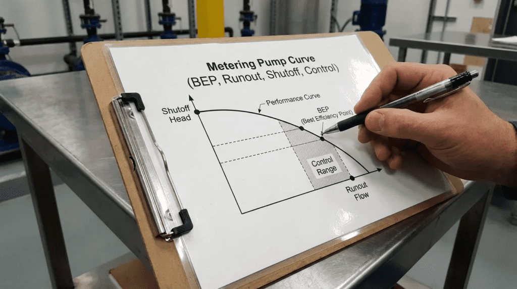
Metering Pumps Pump Curve Reading for Operators (BEP Runout Shutoff and Control) requires a different mindset. A centrifugal pump curve plots Head vs. Flow. A metering pump curve is essentially a plot of Stroke Length/Speed vs. Flow, and it is linear. There is no traditional “Best Efficiency Point” (BEP) on a hydraulic curve; instead, there is a “Best Accuracy Range,” typically between 10% and 100% of capacity. Operators read these curves to correlate VFD speed (Hz) or stroke knob position (%) to expected chemical output.
What is “Runout” in the context of a metering pump?
For a centrifugal pump, runout is high flow at low head, leading to cavitation and motor overload. For a metering pump, “Runout” typically refers to mechanical overspeed. If a VFD drives the motor beyond 60Hz (or the rated speed), the check valves may “float”—fail to seat before the next stroke begins—resulting in a severe drop in volumetric efficiency and accuracy. It can also cause catastrophic gearbox failure.
Why is “Shutoff” dangerous for a metering pump?
A centrifugal pump can run at “Shutoff” (closed discharge valve) for a short period, simply churning the water. A metering pump is positive displacement; it is non-compressible. If run against a closed valve (Shutoff), pressure rises instantly with each stroke until something breaks—usually the piping, the diaphragm, or the drive mechanics. An external Pressure Relief Valve (PRV) is mandatory to prevent this.
How do I control flow: Stroke Length or Stroke Speed?
Stroke length changes the volume displaced per cycle. Stroke speed (via VFD) changes how often that cycle occurs. Best practice is to set the Stroke Length manually to maximize the pump’s displacement (e.g., 80-100%) to ensure good hydraulic compression ratio, and then use the VFD (Speed) for automatic process control. Adjust Stroke Length only if the demand drops below the VFD’s reliable turndown range.
How often should metering pumps be calibrated?
Calibration should occur whenever a new batch of chemical is received (as viscosity/specific gravity may vary slightly), or at least weekly for critical applications like disinfection. Use the calibration column to verify the actual flow rate against the SCADA setpoint. Diaphragm wear over time will gradually reduce the flow per stroke, requiring adjustment.
What is the difference between pulsating and continuous flow?
Diaphragm and plunger pumps produce pulsating flow (sine wave output). Peristaltic and progressive cavity pumps produce near-continuous flow. Pulsating flow can disrupt downstream flow meters and cause pipe vibration. If using a diaphragm pump, pulsation dampeners are essential to smooth the hydraulic profile.
Conclusion
Key Takeaways
- Different Physics: Metering pumps do not follow centrifugal affinity laws for pressure; they are constant flow devices regardless of pressure (up to the relief setting).
- NPSHa is Critical: Always calculate Acceleration Head ($h_a$). Most “bad pumps” are actually bad suction piping designs.
- Safety First: Never operate a PD pump without a downstream pressure relief valve. “Shutoff” head is theoretically infinite and leads to rupture.
- Don’t Oversize: Select a pump where normal operation is 50-80% of capacity. Running at 5% stroke length destroys accuracy.
- Material Matters: Verify chemical compatibility at the maximum design temperature, not just ambient.
The successful implementation of chemical feed systems relies on a specialized understanding of positive displacement hydraulics. Mastering Metering Pumps Pump Curve Reading for Operators (BEP Runout Shutoff and Control) is not about finding a sweet spot on a curve, but about understanding the linear relationship between speed and flow, and the devastating potential of trapped pressure.
For engineers, the task is to specify equipment that fits the hydraulic reality of the piping system, particularly regarding acceleration head and turndown requirements. For operators, the focus must be on rigorous calibration, maintenance of check valves, and understanding that these pumps cannot be “dead-headed” like their centrifugal cousins. By respecting these mechanical realities, utilities can achieve precise chemical dosing, ensuring both fiscal responsibility and environmental compliance.