Pressure Relief Valves for Slurry Service: What Works & Fails
INTRODUCTION
Designing overpressure protection for clean water systems is a relatively straightforward hydraulic exercise; attempting the same for 6% primary sludge, 30% lime slurry, or abrasive mine tailings is an entirely different engineering challenge. When evaluating Pressure Relief Valves for Slurry Service: What Works & Fails is a critical question that separates a safely protected pumping system from a catastrophic blowout. A plugged or jammed relief valve in a positive displacement (PD) pump discharge line can result in fractured pump housings, ruptured piping, and severe safety hazards, often carrying typical damage costs exceeding $50,000 to $100,000 per incident, not including the environmental impact or plant downtime.
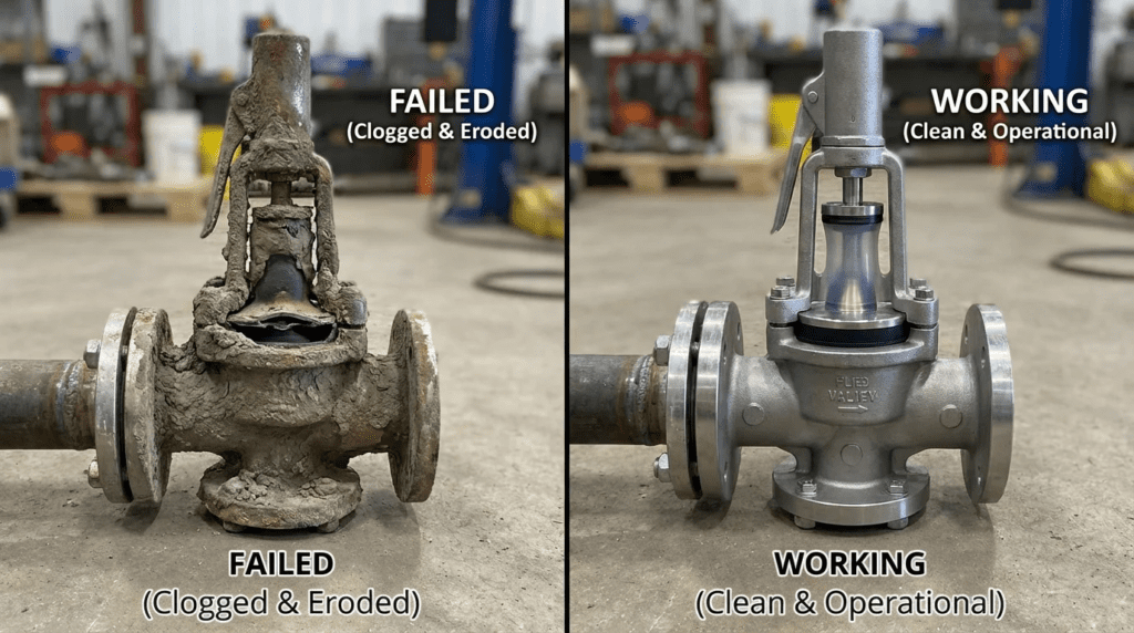
The fundamental problem engineers face is that conventional relief valves are designed for clean, homogenous fluids. In slurry applications, suspended solids settle in the huddling chamber, grit packs into the spring guides, and fibrous materials bind the guiding surfaces. When an overpressure event occurs, the valve has essentially cemented itself shut. Alternatively, abrasive wear during a relief event can destroy a standard valve seat in minutes, causing chronic weeping and loss of process fluid.
This equipment is absolutely critical in municipal wastewater treatment (protecting progressive cavity and rotary lobe pumps handling sludge and biosolids), industrial wastewater processing, lime softening, and mining operations. Any system utilizing a positive displacement pump requires reliable overpressure protection, as these pumps will continue to build pressure against a closed valve or blockage until the motor stalls or the weakest mechanical component fails.
This technical article provides consulting engineers, utility decision-makers, and plant operators with an objective, unbiased framework for specifying this critical equipment. By examining real-world performance data, mechanical limitations, and proper hydraulic design, this guide will help engineers eliminate dead legs, specify the correct valve architectures, and implement reliable lifecycle strategies for severe slurry applications.
HOW TO SELECT / SPECIFY
Specifying relief valves for solids-bearing fluids requires a departure from standard API 520/526 clean-fluid methodologies. Engineers must balance hydraulic capacity with mechanical isolation and abrasion resistance. The following criteria form the foundation of a robust specification.
Duty Conditions & Operating Envelope
The rheology of the process fluid dictates the valve architecture. Engineers must define the specific gravity, percent solids (by weight and volume), and the particle size distribution (PSD). Most wastewater sludges behave as non-Newtonian, Bingham plastic, or pseudo-plastic fluids, meaning their apparent viscosity changes with shear rate.
- Set Pressure: Typically defined as 10% to 15% above the maximum expected operating pressure, ensuring the valve remains tightly closed during normal pressure spikes.
- Accumulation: The allowable pressure increase over the set pressure during a relief event. For slurries, a typical allowable accumulation is 10% to 25%, depending on piping class limits.
- Temperature Limits: Elevated temperatures in processes like thermal hydrolysis or industrial effluent drastically reduce the pressure ratings of elastomer-based valves.
Materials & Compatibility
Material selection in slurry valves is a compromise between abrasion resistance and chemical compatibility. The wetted components must withstand the erosive velocity of the slurry as it accelerates across the relief orifice.
- Elastomers: Natural rubber offers exceptional abrasion resistance for sand and grit but fails rapidly in the presence of hydrocarbons. Nitrile (Buna-N) provides moderate abrasion resistance with excellent oil resistance (typical for primary municipal sludge). EPDM is generally selected for high-pH applications like lime slurry or elevated temperatures.
- Hard Metals: For spring-loaded diaphragm valves or pilot-operated systems (where applicable), trim components must utilize hardened materials such as Tungsten Carbide, Stellite overlays, or high-chrome iron (typically 600+ Brinell hardness) to prevent high-velocity erosion (wire-drawing) during relief events.
- Chemical Compatibility: Ensure all wetted materials are compatible with both the process fluid and any cleaning agents used during Clean-In-Place (CIP) or pipeline flushing procedures.
Hydraulics & Process Performance
Unlike standard PRVs that utilize a tortuous path to dissipate energy, slurry valves require an unobstructed, straight-line flow path whenever possible to prevent bridging and plugging.
- Dead Leg Elimination: The single most critical hydraulic requirement. The valve must be positioned as close to the main process line as physically possible. If a dead leg (a stagnant branch of pipe) exceeds 1.5 to 2 times the pipe diameter, slurry will dewater and pack into a solid plug, rendering the PRV useless.
- Discharge Routing: Slurry PRV discharge should ideally be routed back to the source tank or wet well. Routing back to the pump suction is highly discouraged for PD pumps, as it can cause localized heating, vapor locking, and rapid accumulation of concentrated solids.
Installation Environment & Constructability
The physical installation dictates the long-term viability of the valve. Space constraints often force poor piping layouts, which must be avoided at the design phase.
- Orientation: Valve bodies should be installed vertically where possible to prevent solids from settling asymmetrically on the sealing surfaces or diaphragms.
- Flushing Ports: The specification must mandate integrated flush ports on both the inlet and outlet sides of the valve to allow operators to clean the seat after a relief event or during routine maintenance.
- Structural Support: Slurry piping experiences severe dynamic loading during a relief event. Thrust blocks or engineered pipe supports are mandatory to handle the sudden transfer of momentum when a dense slurry accelerates through the discharge line.
Reliability, Redundancy & Failure Modes
When evaluating Pressure Relief Valves for Slurry Service: What Works & Fails in terms of reliability depends heavily on minimizing mechanical complexity in the fluid path.
- Failure to Open (Plugging): The most catastrophic failure mode. Caused by dewatering in dead legs, chemical scaling (lime), or mechanical binding of trim components by grit.
- Failure to Close (Weeping): Occurs when solids get trapped between the seat and the plug/diaphragm after a relief event, preventing a tight seal. This leads to continuous high-velocity leakage, which quickly destroys the valve through erosion.
- Redundancy: For critical PD pump systems, a dual-valve arrangement with a clean-out spool or interlocking isolation valves (subject to strict administrative lock-out controls) allows for online maintenance without shutting down the process.
Controls & Automation Interfaces
While mechanical PRVs are self-actuating, integrating them into the plant SCADA system provides critical diagnostic data.
- Proximity Switches: Rupture pin valves and some pinch valves can be fitted with limit switches or proximity sensors to immediately alert the control room that a relief event has occurred.
- Pressure Monitoring: Rather than relying solely on the PRV, modern systems use pressure transmitters to shut down the pump via the VFD before the mechanical relief valve is forced to open. The PRV acts as the ultimate mechanical failsafe, not the primary control loop.
Maintainability, Safety & Access
Maintenance personnel must be able to service the valve safely, often while dealing with hazardous biological or chemical fluids.
- Lockout/Tagout (LOTO): Double block and bleed arrangements on the discharge side are necessary if the valve relieves into a pressurized header.
- Ergonomics: Large slurry valves are incredibly heavy. Designs must include lifting lugs and be positioned in areas accessible by overhead cranes or mobile lifting equipment.
- Inline Serviceability: Valves that allow diaphragm or rupture pin replacement without removing the entire valve body from the piping matrix significantly reduce maintenance labor hours.
Lifecycle Cost Drivers for Pressure Relief Valves for Slurry Service: What Works & Fails
Evaluating total cost of ownership (TCO) requires looking beyond the initial capital expenditure (CAPEX).
- CAPEX vs OPEX: A basic rupture disc may cost $500 (low CAPEX), but replacing it requires breaking flanges, halting production, and cleaning the line (high OPEX). An air-loaded pinch valve may cost $6,000 (high CAPEX) but automatically resets and flushes cleanly (low OPEX).
- Spare Parts: Engineers should evaluate the cost of replacement elastomers, diaphragms, and rupture pins. Ensure the manufacturer guarantees long-term availability of these specific compounds.
COMPARISON TABLES
The following tables provide an objective evaluation of the primary technologies utilized for slurry overpressure protection, along with an application fit matrix. These comparisons are based on typical municipal and industrial field performance, highlighting inherent mechanical strengths and limitations.
| Technology / Valve Type | Primary Mechanism | Best-Fit Applications | Limitations & Vulnerabilities | Typical Maintenance Profile |
|---|---|---|---|---|
| Elastomer Pinch Valve (Air or Spring Loaded) | A flexible elastomer sleeve is compressed by air pressure or a mechanical spring. Overpressure overcomes the closing force, expanding the sleeve. | Municipal sludge, highly abrasive slurries, high percent solids (up to 50%+). | Elastomer degrades at high temperatures (>200°F) or with certain chemicals. Air-loaded requires reliable plant air. | Sleeve replacement every 3-5 years. Very low routine maintenance. Flushes clean easily. |
| Rupture Pin Valve | A piston is held closed by an external, precisely machined buckling pin. Overpressure buckles the pin, instantly fully opening the valve. | High-pressure sludge, applications requiring instant, full-bore relief and positive visual indication. | Does not automatically reset; requires manual intervention and pin replacement after every event. | Pin replacement after every relief event (typically takes 5-10 minutes). O-ring inspection annually. |
| Diaphragm-Isolated Spring PRV | A flexible diaphragm physically separates the slurry from the mechanical spring and guiding components. | Light sludges, chemical dosing (polymers), low-to-medium pressure applications. | Diaphragms can rupture under severe pressure spikes. Solids can still settle in the lower body cavity. | Diaphragm replacement every 1-3 years. Requires frequent flushing of the lower body. |
| Rupture Discs (Burst Discs) | A sacrificial metallic or graphite membrane engineered to fail at a specific pressure. | Ultimate failsafe behind a primary PRV; severe chemical applications. | Total loss of process fluid until system is shut down. High labor to replace. Prone to fatigue failure from pressure pulsation. | Complete replacement required after every event. Frequent inspection for fatigue/corrosion. |
| Process Fluid / Scenario | Key Challenges | Optimal Valve Selection | Secondary Alternative | Relative CAPEX Impact |
|---|---|---|---|---|
| Primary Raw Sludge (3-6% solids) | High grit content, rags, stringy material, grease buildup. | Air-Loaded Pinch Valve | Rupture Pin Valve | Moderate to High |
| Thickened Waste Activated Sludge (TWAS) | Viscous, non-Newtonian behavior, bio-gas entrainment. | Diaphragm-Isolated Spring PRV | Air-Loaded Pinch Valve | Low to Moderate |
| Lime Slurry (20-30% solids) | Severe scaling, rapid settling/dewatering, abrasive. | Rupture Pin Valve (with flush ports) | Elastomer Pinch Valve (EPDM) | High |
| Mine Tailings / Sand Slurry | Extreme abrasion, high fluid density, high velocity erosion. | Heavy-Duty Pinch Valve (Natural Rubber) | Rupture Disc (as ultimate failsafe) | High |
| Polymer / Chemical Feed | High viscosity, shear sensitivity, chemical compatibility. | Diaphragm-Isolated Spring PRV | Standard Spring PRV (if clean) | Low |
ENGINEER & OPERATOR FIELD NOTES
Theoretical sizing is only the first step. The reality of operating a sludge or slurry line dictates that valves must be commissioned correctly and maintained rigorously. The following field notes bridge the gap between design specifications and plant floor realities.
Commissioning & Acceptance Testing
Commissioning a slurry PRV with actual process fluid is dangerous and impractical. Testing must be completed systematically before the process goes live.
- Hydrostatic Testing: Ensure the valve is isolated or rated to withstand piping system hydro-tests. Standard practice is to test piping at 1.5x design pressure, which will inadvertently actuate or damage a PRV set to 1.1x design pressure if not properly blinded or isolated.
- Set Pressure Verification (SAT): Verify the opening pressure using clean water during the Site Acceptance Test. Gradually increase pump speed against a closed downstream isolation valve to document the exact opening pressure and verify SCADA alarms.
- Pulsation Dampener Balancing: In systems with PD pumps, ensure pulsation dampeners are properly charged. Un-dampened pressure spikes can cause the PRV to chatter, prematurely destroying elastomers and pins.
The most frequent specification error is cutting and pasting standard clean-water PRV specifications (like API 526 direct spring valves) into a sludge pumping project. These valves utilize small, tortuous internal passages that will plug with biosolids within the first 48 hours of operation, resulting in zero overpressure protection.
Common Specification Mistakes
Engineers often introduce failure points through ambiguous or incomplete bid documents.
- Ignoring the Dead Leg: Specifying a standard tee-fitting for the PRV branch creates a dead leg. Best practice is to specify a “flow-through” or “cross” style configuration, or use a saddle connection that keeps the valve diaphragm perfectly flush with the main pipeline flow.
- Undersizing the Discharge Line: The discharge piping must be at least the same diameter as the valve outlet, but ideally one size larger. Slurry flashing or expanding into a restrictive pipe will cause backpressure, which changes the set pressure of unbalanced PRVs.
- Vague Material Specs: Stating “elastomer trim” is insufficient. Specify “100% Neoprene” or “Natural Rubber with shore hardness X” based on the specific hydrocarbon or abrasion profile of the slurry.
O&M Burden & Strategy
A proactive maintenance strategy is the only way to ensure PRVs operate when called upon.
- Routine Flushing: Operators must establish a strict schedule (weekly or bi-weekly) to flush the inlet connection of the PRV with high-pressure clean water. This prevents dewatering and consolidation of the slurry plug.
- Post-Relief Protocol: Any time a slurry PRV actuates, it must be flushed immediately. If a pinch valve or diaphragm valve closes on a piece of grit or a fibrous rag, it will weep process fluid. This high-velocity leak will wire-draw and destroy the elastomer in a matter of days.
- Spare Parts Inventory: Plants must keep at least one full rebuild kit (sleeves, diaphragms, or minimum 5 rupture pins) in climate-controlled inventory. Elastomers degrade in hot, UV-exposed storage sheds.
Troubleshooting Guide
When valves malfunction, rapid diagnosis prevents collateral system damage.
- Symptom: Valve Chattering. Root Cause: Oversized valve, high piping pressure drop, or un-dampened PD pump pulsations. Fix: Charge pulsation dampeners, check VFD settings, or evaluate if the PRV requires a smaller orifice.
- Symptom: Continuous Weeping. Root Cause: Debris trapped in the seat, or erosion damage to the diaphragm/sleeve. Fix: Perform a high-pressure flush. If weeping persists, the valve must be isolated and the elastomer replaced.
- Symptom: Premature Actuation. Root Cause: Material fatigue (rupture discs), incorrect air loading pressure (pinch valves), or degraded springs. Fix: Recalibrate air regulators, verify process temperature hasn’t exceeded material limits, replace fatigued components.
DESIGN DETAILS / CALCULATIONS
Accurate sizing and rigorous specification standards ensure the valve can handle the necessary capacity without inducing damaging velocities.
Sizing Logic & Methodology
Sizing for slurry requires modifying standard liquid equations (like those found in API 520 Part I) to account for viscosity and specific gravity.
- Determine Required Capacity ($Q$): For a positive displacement pump, the required relief capacity is 100% of the pump’s maximum design flow rate at the specified motor RPM. Do not size for “normal” flow; size for absolute maximum volumetric output.
- Calculate Effective Orifice Area: Use standard liquid equations, but apply a viscosity correction factor ($K_v$). Highly viscous sludges (e.g., thickened sludge >6% solids) create high frictional losses through the valve orifice.
- Check Velocity Limits: This is unique to slurry. The fluid velocity through the valve orifice and discharge piping must be kept below typical erosive limits (approximately 10-15 feet per second for mild sludges, and strictly <8 fps for highly abrasive sand slurries). If the calculated velocity is too high, a larger valve size or multiple parallel valves must be specified.
Do not assume a specific gravity of 1.0. Primary sludge typically ranges from 1.01 to 1.05, but lime slurry can exceed 1.2, and mine tailings can approach 1.8. A higher specific gravity requires a larger orifice area to relieve the same volumetric flow rate safely.
Specification Checklist
A comprehensive engineering specification for a slurry PRV should explicitly include:
- Body Design: “Valve shall feature a straight-through, non-clogging flow path with no dead spaces or internal cavities where solids can accumulate.”
- Isolation: “Operating mechanisms (springs, pistons) shall be 100% isolated from the process fluid.”
- Flush Ports: “Valve body or mating spools shall include minimum 1-inch NPT flush ports upstream and downstream of the seating area.”
- Testing: “Manufacturer shall provide certified test reports demonstrating set pressure verification and hydrostatic body testing in accordance with ASME/ANSI standards.”
- Coating: “Exterior surfaces shall be coated with two-part epoxy suitable for corrosive H2S environments.”
Standards & Compliance
While standard PRV codes are heavily focused on oil, gas, and steam, several standards provide frameworks for slurry piping.
- ASME B16.5 / B16.47: Dictates the dimensional and pressure-temperature ratings of the valve flanges.
- ASME Section VIII: While many slurry PRVs do not carry a “U” or “UV” stamp because they are not protecting compressible gas pressure vessels, the design and testing of the bodies often conform to these rigorous safety margins.
- AWWA Standards: There is no specific AWWA standard for sludge PRVs; however, the mating piping and isolation valves should adhere to AWWA C110/C115 (flanged fittings) and relevant lining standards.
FAQ: Pressure Relief Valves for Slurry Service: What Works & Fails
What is a pressure relief valve for slurry service?
A slurry pressure relief valve is an automated safety device designed to open and vent fluid when pressure exceeds a predetermined limit, specifically engineered to handle liquids containing high concentrations of suspended solids, abrasives, or stringy materials without plugging or wearing out prematurely.
How do you select the right PRV for non-Newtonian sludge?
Selection depends on identifying the fluid’s specific gravity, maximum percent solids, and abrasion profile. For high-solids, fibrous sludges, air-loaded pinch valves or rupture pin valves are typically selected because they offer straight-through flow paths and eliminate the huddling chambers where solids pack and cause standard valves to fail.
What is the difference between a pinch valve PRV and a standard spring-loaded PRV?
A standard spring-loaded PRV uses a metal disc pressed against a seat by a mechanical spring, forcing fluid through a complex, tortuous path. A pinch valve PRV uses air pressure or a mechanical mechanism to compress a straight elastomer sleeve. When pressure spikes, the sleeve expands, offering a full-bore, unobstructed path for the slurry, preventing blockages.
How often should slurry PRVs be maintained?
Maintenance frequency depends on the service severity. Inlet flushing should occur weekly or bi-weekly. Preventive maintenance, such as replacing the elastomer sleeve or isolating diaphragm, is typically recommended every 2 to 5 years. Any time the valve actuates to relieve pressure, it must be immediately flushed to prevent debris from keeping the seat open.
How much do slurry pressure relief valves typically cost?
Costs vary widely based on size and technology. A simple 2-inch diaphragm-isolated PRV may cost $1,500 to $3,000. Heavy-duty 4-inch to 6-inch air-loaded pinch valves or rupture pin valves typically range from $5,000 to $15,000+, depending on flange ratings, materials, and integrated sensor options.
Why do traditional relief valves fail in lime slurry?
Lime slurry is notorious for rapid settling and aggressive chemical scaling. In a traditional valve, the slurry enters the lower body cavity and dewaters, forming a concrete-like plug. When an overpressure event occurs, the valve is physically cemented shut and cannot lift, leading to system over-pressurization.
Are rupture discs a viable option for wastewater sludge?
Rupture discs are highly reliable from a failsafe perspective because they offer a full-bore opening. However, they are generally discouraged as the primary relief method in wastewater because they cause a total loss of system containment and require process shutdown, line drainage, and significant maintenance labor to replace after every single overpressure event.
What is a dead leg, and why is it dangerous in slurry piping?
A dead leg is a stagnant branch of piping leading to a closed valve. In slurry systems, the solids in this stagnant fluid quickly settle out and compact. If a PRV is installed at the end of a long dead leg, the compacted solids act as a rigid pipe plug, preventing the pressure from reaching the valve and neutralizing the overpressure protection.
CONCLUSION
KEY TAKEAWAYS
- Eliminate Dead Legs: The valve must be mounted as flush to the main process flow as mechanically possible. Dead legs >1.5x pipe diameter guarantee plugging.
- Isolate Mechanics: Springs, guides, and pistons must never contact the slurry. Specify pinch valves, rupture pins, or diaphragm-isolated bodies.
- Size for Maximum PD Output: Always size the relief capacity for 100% of the positive displacement pump’s absolute maximum theoretical output, adjusting for specific gravity and viscosity.
- Manage Velocity: High velocities during relief events destroy elastomers and metals. Keep discharge velocities below typical erosive limits (10-15 fps for sludge, <8 fps for sand/grit).
- Mandate Flushing Protocols: A PRV that actuates and closes on debris will weep and quickly self-destruct. Integrated flush ports and strict post-event flushing routines are mandatory.
Successfully navigating Pressure Relief Valves for Slurry Service: What Works & Fails requires a fundamental shift in engineering perspective. Standard clean-water hydraulics and off-the-shelf API 526 valves have no place in a heavy sludge or grit environment. By focusing on fluid rheology, prioritizing straight-through flow paths, and aggressively minimizing dead legs, engineers can specify overpressure protection systems that genuinely protect the plant infrastructure.
The decision framework must ultimately balance upfront capital costs against the operational realities of the plant. A valve that saves $2,000 in CAPEX but requires breaking flanges every month to clear blockages is a liability, not an asset. Plant directors and consulting engineers should involve specialty manufacturers early in the design phase, utilize the application fit matrices provided above, and ensure that the final bid specifications rigorously demand appropriate elastomer materials, flush ports, and robust documentation.
Ultimately, a well-specified slurry pressure relief valve acts as a silent guardian. With proper selection, proactive maintenance, and strict adherence to hydraulic best practices, these critical safety devices will ensure the longevity of high-value pumping equipment and the safety of the operators who manage them.