Valves – Service Sizing and Selection: Cv
INTRODUCTION
One of the most persistent and costly errors in municipal water and wastewater engineering is the practice of “line-sizing” control valves. When engineers default to matching a control valve’s diameter to the adjoining pipe size, the result is almost always an oversized valve. A poorly sized valve operating continuously between 10% and 20% open will suffer from poor control resolution, wire drawing, and catastrophic cavitation. In high-pressure water distribution systems, an improperly specified valve can literally tear itself apart within 18 to 24 months, leading to unplanned outages and tens of thousands of dollars in replacement costs. To prevent this, the rigorous process of Valves – Service Sizing and Selection: Cv must be the foundation of any fluid control design.
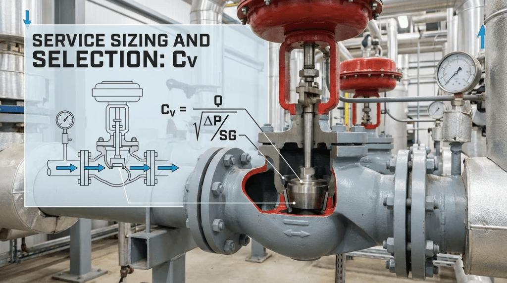
The flow coefficient, universally designated as Cv, is the fundamental metric used to size and select valves for liquid service. By definition, Cv represents the volume of water (in US gallons) at 60°F that will flow through a valve per minute with a pressure drop of exactly 1 psi across the valve. Understanding, calculating, and applying the correct Cv is critical in applications ranging from municipal pump station discharge control and pressure reducing stations, to precise chemical dosing and return activated sludge (RAS) modulation.
Proper valve sizing is a delicate balancing act. An oversized valve (excessive Cv) yields poor control, hunts for its setpoint, and risks seat damage. An undersized valve (insufficient Cv) acts as a permanent bottleneck, artificially shifting the system curve, wasting pumping energy, and potentially causing choked flow. This article provides consulting engineers, plant operators, and utility managers with a comprehensive, unbiased framework for specifying liquid control valves based on rigorous hydraulic principles, real-world lifecycle costs, and proven operational reliability.
HOW TO SELECT / SPECIFY
The engineering workflow for Valves – Service Sizing and Selection: Cv must move sequentially from process duty conditions to physical installation constraints. Relying on generalized rules of thumb without calculating specific operating points guarantees suboptimal performance.
Duty Conditions & Operating Envelope
The foundation of valve sizing is defining the complete operating envelope. A single design point is never sufficient. Engineers must identify three specific flow conditions: minimum ($Q_{min}$), normal/typical ($Q_{normal}$), and maximum ($Q_{max}$) flow rates. Corresponding with these flows, the upstream pressure ($P_1$) and downstream pressure ($P_2$) must be determined to calculate the expected pressure drop ($Delta P$) under all three scenarios.
- Continuous vs. Intermittent: A valve throttling RAS continuously requires a different wear profile and duty cycle rating than a valve used for intermittent filter backwash flow control.
- Future Capacity: Designing for 20-year future peak flows often results in valves that are drastically oversized for Year 1 conditions. In these cases, consider installing smaller trim sets initially or utilizing parallel valve configurations (e.g., a 4-inch and 12-inch valve in parallel to handle high turndown requirements).
- Vapor Pressure: The fluid temperature and its corresponding vapor pressure ($P_v$) must be recorded to accurately predict the onset of cavitation at high velocities.
Materials & Compatibility
Once the required Cv establishes the physical size and internal geometry of the valve, material selection dictates its longevity. In water and wastewater, materials must withstand corrosion, abrasion, and specific chemical attacks.
- Abrasion Considerations: Raw wastewater and primary sludge contain significant grit. Modulating valves in this service (such as eccentric plug valves) require hardened trims. Stellite overlays or 316 Stainless Steel with hardened coatings (like Chrome Carbide) are typical for severe service.
- Chemical Compatibility: In dosing applications (e.g., sodium hypochlorite, ferric chloride), standard wetted materials will fail rapidly. Titanium, Hastelloy, or PTFE-lined bodies and internals are often mandatory.
- Elastomers: Chloraminated municipal water can rapidly degrade standard Buna-N or EPDM elastomers. EPDM peroxide-cured or specific chloramine-resistant elastomers must be specified for seats and seals in potable water distribution.
Hydraulics & Process Performance
The core of Valves – Service Sizing and Selection: Cv is matching the valve’s “inherent flow characteristic” to the system’s requirements. The inherent characteristic describes how the valve’s Cv changes as the valve travels from 0% to 100% open.
- Linear Characteristic: The flow capacity increases linearly with valve travel. Best suited for liquid level control or systems where the major pressure drop is taken across the valve itself.
- Equal Percentage: Equal increments of valve travel produce equal percentage changes in the existing Cv. This is the most common characteristic used in liquid control applications because it compensates for typical centrifugal pump curves and pipe friction, yielding an “installed characteristic” that is close to linear.
- Quick Opening: Provides maximum change in flow rate at low travel. Primarily used for on/off isolation service rather than modulating control.
- Valve Authority: This represents the ratio of pressure drop across the fully open valve to the total pressure drop of the entire system. A control valve should typically have an authority of at least 0.25 to 0.30 (25-30%) to maintain effective control without hunting.
Installation Environment & Constructability
Hydraulic performance is heavily dependent on the installation environment. Valves installed immediately downstream of elbows, reducers, or pumps will experience turbulent, asymmetrical flow profiles that alter the published Cv curve and increase noise and vibration.
- Straight Run Requirements: Standard engineering practice dictates a minimum of 5 pipe diameters (5D) of straight, undisturbed pipe upstream and 3 pipe diameters (3D) downstream of a control valve.
- Orientation: Actuators for large butterfly or plug valves can be excessively heavy. Specifying the valve with the shaft horizontal rather than vertical is often necessary to prevent bottom bearing failure due to the weight of the disc/plug, particularly in sizes exceeding 24 inches.
- Space Constraints: Control valves require clearance for actuator removal, packing adjustments, and positioner calibration. Do not place control valves in shallow vaults where operators cannot safely stand to perform lockout/tagout (LOTO) and maintenance.
Reliability, Redundancy & Failure Modes
Understanding how a valve will fail is as important as understanding how it operates. Engineers must specify the “fail-safe” position upon loss of motive power (pneumatic air or electricity) or loss of control signal (4-20mA).
- Fail Closed (FC): Typical for chemical feed or tank fill lines to prevent flooding or overdosing.
- Fail Open (FO): Typical for bypass lines or pressure relief applications where system pressure must be maintained.
- Fail Last Position (FL): Often achieved with electric motor actuators or pneumatic systems with lock-up valves; used in filter effluent control where sudden changes in flow would disrupt the treatment process.
- Common Failure Modes: In municipal applications, common causes of reduced Mean Time Between Failures (MTBF) include “stiction” (static friction exceeding dynamic friction, causing erratic jumping), packing leaks, and trim erosion due to cavitation.
Controls & Automation Interfaces
The transition from a theoretical Cv calculation to physical flow modulation relies on the positioner and actuator assembly. Modern water and wastewater facilities rely on smart positioners integrated into SCADA systems.
- Position Feedback: A 4-20mA command signal dictates the setpoint, but a separate 4-20mA feedback signal is critical for the PLC to confirm the valve actually achieved the commanded position.
- Smart Diagnostics: Digital positioners (HART, Foundation Fieldbus, Profibus DP) can track cumulative valve travel, cycle counts, and breakout friction. This data is invaluable for predictive maintenance.
- Actuator Sizing: Actuators must be sized not just for the static pressure differential, but for the maximum dynamic torque required to seat/unseat the valve against the maximum possible differential pressure, factoring in an appropriate safety margin (typically 1.25 to 1.5).
Maintainability, Safety & Access
Control valves are high-wear items requiring regular maintenance. If a valve is inaccessible, it will not be maintained until it fails catastrophically.
- Isolation: Modulating valves must have manual isolation valves installed both upstream and downstream to allow for trim replacement without draining the entire system.
- Bypass Lines: For critical continuous processes (like high-service pumping), a bypass line equipped with a manual throttling valve should be designed around the control valve.
- Lifting Provisions: Any valve assembly exceeding 50 lbs must include engineered lifting lugs. Overhead clearance must be designed to accommodate hoists or gantry cranes.
Lifecycle Cost Drivers
Capital Expenditure (CAPEX) for a control valve is a fraction of its Total Cost of Ownership (TCO). Operational Expenditure (OPEX) drivers include:
- Energy Consumption: Selecting a valve type with an inherently low full-open Cv (high pressure drop) forces the pumps to work harder continuously, resulting in thousands of dollars in wasted electrical energy annually.
- Replacement Frequency: Spending 30% more upfront for severe-service anti-cavitation trim can extend the valve’s lifespan from 2 years to 10+ years, offering a massive ROI in parts and labor savings.
COMPARISON TABLES
The following tables provide an unbiased comparison of common valve technologies and their ideal application fit within water and wastewater systems. Use these tables to narrow down the mechanical valve style before executing specific Cv calculations.
| Technology / Type | Inherent Characteristic | Typical Turndown | Best-Fit Applications | Limitations / Maintenance |
|---|---|---|---|---|
| Globe Valve | Linear or Equal % | 30:1 to 50:1 | Clean water, high pressure drop, precise flow control, PRV stations. | High pressure loss even when fully open. Will clog instantly in raw wastewater. High CAPEX. |
| High-Performance Butterfly (HPBV) | Equal % | 20:1 | Large diameter clean water, filter effluent, aeration air control. | Prone to cavitation at angles < 20° open. Unsuitable for stringy solids. |
| Eccentric Plug Valve | Modified Linear | 10:1 | Raw wastewater, raw sludge, grit-laden flows. | Poor control resolution near the closed position. Heavy actuators required. |
| V-Port Ball Valve | Equal % | 100:1 to 300:1 | Thick sludge, digester gas, high-turndown requirements. | Can be expensive in large diameters. Requires careful seating maintenance. |
| Pinch Valve | Quick Opening / Linear | 5:1 to 10:1 | Lime slurry, highly abrasive sludge, chemical feed. | Sleeve replacement is required routinely. Bulky footprint. |
| Application Scenario | Key Fluid Constraints | Recommended Valve Type | Sizing Priority | Relative Cost |
|---|---|---|---|---|
| Municipal Pump Station Discharge | High pressure, clean water, pump start/stop transients | Globe Valve with Anti-Cavitation Trim or Rotary Cone | Prevent cavitation at low flows; ensure linear installed characteristic. | High |
| Return Activated Sludge (RAS) Control | 0.5% – 1.5% solids, low pressure drop | Eccentric Plug or V-Port Ball | Pass solids without ragging; target 50-60% open for normal flow. | Medium |
| Gravity Filter Effluent Control | Very low pressure drop, clean water, high precision | AWWA Butterfly with Characterized Disc | Minimize head loss fully open; accurate control between 20-60°. | Low/Medium |
| Lime Slurry Dosing | Highly abrasive, prone to scaling and settling | Pinch Valve | Size to maintain high line velocity to prevent solids settling. | Medium |
ENGINEER & OPERATOR FIELD NOTES
Executing a design on paper is only the first step. The translation of a specification into a functioning system requires rigorous testing, vigilance against common documentation errors, and a proactive maintenance strategy.
Commissioning & Acceptance Testing
Do not accept a control valve installation without verifying its performance against the calculated parameters.
- Factory Acceptance Test (FAT): For critical valves, mandate an FAT that includes hydrostatic shell testing, seat leakage testing (per ANSI/FCI 70-2, typically Class IV or VI for municipal service), and a full stroke test to verify actuator travel times against the specification.
- Site Acceptance Test (SAT): During SAT, stroke the valve from 0% to 100% using the SCADA system, not just the local handwheel. Verify the feedback signal tracks precisely with the command signal.
- Deadband Verification: Induce small step changes (e.g., 2% increments). If the valve does not move until a 4% or 5% change is commanded, the assembly has excessive deadband (usually mechanical slop or actuator friction), which will cause the PID loop to oscillate continuously.
Common Specification Mistakes
When applying the principles of Valves – Service Sizing and Selection: Cv, engineers frequently fall into several predictable traps.
- The “Line-Size” Trap: Writing a spec that says “Control valve shall be the same size as the connecting piping.” This ignores hydraulics entirely. A 12-inch pipe may only require an 8-inch control valve to achieve the proper pressure drop and control authority.
- Over-Conservatism: Stacking safety factors. The process engineer adds 10% to the flow, the mechanical engineer adds 10% to the head, and the valve supplier rounds up to the next size. The result is a valve that operates at 15% open during normal conditions.
- Ignoring Turndown Limits: Expecting a standard butterfly valve to control flow effectively from 500 GPM to 10,000 GPM. A standard butterfly valve has a practical turndown of roughly 10:1 or 20:1. Extreme ranges require specialized valves or a split-ranging parallel setup.
O&M Burden & Strategy
Maintenance teams must transition from reactive fixing to predictive maintenance, leveraging the smart technology built into modern valve actuators.
- Routine Inspections: Annually check packing glands for leakage. Do not overtighten packing to stop a leak, as this increases stem friction, causing stiction and erratic control. Repack the valve properly during a planned outage.
- Predictive Diagnostics: Utilize smart positioner software to trend “friction over time.” A steady increase in required actuation force indicates galling of the stem or build-up of process scale on the trim. Schedule cleaning before the actuator fails on thermal overload.
- Spare Parts Inventory: Maintain soft goods kits (O-rings, packing, gaskets, diaphragm if applicable) for all critical control valves. For severe service valves, keep one complete spare trim set (plug and seat ring) in local inventory.
Troubleshooting Guide
When an existing control valve misbehaves, operators must systematically identify the root cause.
- Symptom: Hunting/Oscillating. The valve constantly opens and closes around a setpoint. Root Cause: Often an oversized valve (Cv too high for the flow), excessive mechanical deadband, or overly aggressive PID tuning in the PLC. Fix: First, slow down the PID loop. If mechanical deadband is confirmed, check linkages. If the valve is oversized, consider installing reduced-port trim.
- Symptom: Chattering/Hammering near closed position. Root Cause: Operating too close to the seat, flow opposing the closing direction causing dynamic instability. Fix: Verify correct flow direction through the body; adjust process setpoints to keep the valve further open.
- Symptom: Excessive Noise/Vibration. Root Cause: Cavitation or choked flow. Fix: Increase downstream pressure (add a backpressure orifice) or replace the trim with an anti-cavitation multi-stage cage design.
DESIGN DETAILS / CALCULATIONS
Accurate implementation of Valves – Service Sizing and Selection: Cv relies heavily on empirical formulas published by industry standard organizations.
Sizing Logic & Methodology
The standard equation for calculating the flow coefficient for incompressible fluids (liquids) is:
$C_v = Q times sqrt{frac{G}{Delta P}}$
Where:
- $C_v$ = Valve flow coefficient
- $Q$ = Flow rate in US Gallons per Minute (GPM)
- $G$ = Specific gravity of the fluid (Water at 60°F = 1.0; Raw sludge may be 1.02 to 1.05)
- $Delta P$ = Pressure drop across the valve ($P_1 – P_2$) in psi.
Step-by-Step Sizing Approach:
- Calculate the required Cv for $Q_{min}$, $Q_{normal}$, and $Q_{max}$.
- Select a valve size where the required $C_{v(normal)}$ falls between 50% and 70% of the valve’s published maximum Cv.
- Verify that the required $C_{v(min)}$ does not fall below 15-20% of the valve’s travel (to prevent seat wear and poor resolution).
- Verify that the required $C_{v(max)}$ does not exceed 85-90% of the valve’s travel (to maintain a margin of control authority).
- Calculate the Cavitation Index ($sigma$) using the formula: $sigma = (P_1 – P_v) / (P_1 – P_2)$. If $sigma$ is less than typical safe limits (e.g., < 1.5 for basic valves), specialized anti-cavitation trim is mandatory.
Specification Checklist
A robust specification for a control valve in a water or wastewater facility must detail the following:
- Tag Number & Service: (e.g., CV-101, Filter 1 Effluent Modulating)
- Required Cv: List the calculated min, norm, and max Cv requirements.
- Valve Style & Body Material: (e.g., V-port ball, Ductile Iron ASTM A536)
- Trim Material: (e.g., 316 SS with Stellite 6 overlay)
- ANSI Pressure Class: (e.g., Class 150, Class 300)
- Leakage Standard: ANSI/FCI 70-2 Class (Class VI for bubble-tight shutoff)
- Actuation & Fail Safe: (e.g., Electric motor, fail last position)
- Inherent Characteristic Required: (e.g., Equal Percentage)
Standards & Compliance
Municipal engineers must navigate a blend of standards. The instrumentation society standards focus heavily on control mathematics, while municipal standards focus heavily on ruggedness and isolation.
- ISA 75.01.01: The definitive standard for flow equations for sizing control valves. This standard governs the mathematical models for calculating Cv, choked flow, and cavitation prediction.
- AWWA Standards: Standards such as AWWA C504 (Rubber-Seated Butterfly Valves) or AWWA C507 (Ball Valves) specify shaft diameters, seating mechanics, and body thicknesses. Important Note: AWWA standards were traditionally written for isolation valves. When specifying an AWWA valve for modulating control, engineers must add supplemental requirements for shaft-to-disc pinning (to prevent fatigue failure from continuous modulation) and tighter actuator backlash limits.
- NSF/ANSI 61 & 372: Mandatory for all wetted parts in potable water service to ensure no toxic leaching or lead content.
FAQ SECTION
What is the difference between inherent and installed Cv?
The inherent Cv is the flow capacity of the valve measured on a test stand under constant pressure drop conditions, as published by the manufacturer. The installed Cv (or installed characteristic) accounts for the dynamic pressure changes in the actual piping system. Because piping friction and pump curves change the pressure drop across the valve as it modulates, the installed characteristic differs significantly from the inherent characteristic.
How do you calculate Cv for liquid valves in wastewater?
The fundamental equation is $C_v = Q sqrt{G / Delta P}$. In wastewater, you must accurately determine the specific gravity (G) of the fluid. While clean water has a G of 1.0, primary sludge or RAS may have a specific gravity of 1.02 to 1.05 depending on solids concentration. Additionally, the sizing must account for the viscosity of thick sludges, which may require correction factors to the standard Cv equation.
Why shouldn’t I just size the control valve to match the pipe diameter?
Pipes are sized to minimize head loss and keep velocities within a safe range (typically 3-8 ft/sec). Control valves, however, must create head loss to control flow. If a valve is line-sized, it will have a much higher Cv than the system requires, forcing the valve to operate nearly closed (10-20% open). This leads to poor control resolution, premature wear, and cavitation damage.
What happens if a control valve’s Cv is too high?
If a valve’s Cv is too high (oversized), a very small movement of the actuator results in a massive change in flow. The control loop will constantly overshoot the setpoint, causing the valve to “hunt” or oscillate. Furthermore, operating near the closed position accelerates wear on the plug and seat (wire drawing) and severely increases the risk of cavitation.
What happens if a control valve’s Cv is too low?
If a valve is undersized (Cv is too low), it creates excessive pressure drop even when 100% open. This limits the maximum flow capacity of the system, acting as a permanent bottleneck. It also forces the upstream centrifugal pumps to ride further left on their curves, wasting electrical energy to overcome the artificial head loss created by the small valve.
How does the process of Valves – Service Sizing and Selection: Cv apply to sludge applications?
Sizing valves for sludge requires balancing hydraulic theory with physical reality. While the Cv calculation might indicate a 3-inch valve is hydraulically perfect, a 3-inch valve will instantly plug with rags and debris found in raw sludge. Engineers must often select a larger valve size to pass solids (e.g., minimum 6-inch for raw sewage), and then utilize V-port or characterized trims to artificially lower the valve’s Cv to achieve the required control without clogging.
CONCLUSION
KEY TAKEAWAYS
- Never Line-Size: Always calculate the required Cv for minimum, normal, and maximum flow conditions rather than matching pipe diameters.
- Target the Sweet Spot: Select a valve where the normal operating flow occurs between 50% and 70% of the valve’s full travel.
- Analyze Authority: Ensure the valve pressure drop at maximum flow is at least 25-30% of the total system dynamic friction to maintain control authority.
- Beware Cavitation: Calculate the cavitation index ($sigma$) for minimum flow/high differential pressure scenarios; specify hardened or anti-cavitation trim if required.
- Equal Percentage for Liquids: Specify an equal percentage inherent flow characteristic for most pumping applications to achieve a linear installed characteristic.
The discipline of Valves – Service Sizing and Selection: Cv is the ultimate intersection of fluid mechanics, mechanical engineering, and process control. Municipal engineers and utility managers cannot afford to treat control valves as passive pipe fittings. They are active, high-stress process instruments that dictate the hydraulic stability and energy efficiency of the entire treatment facility or distribution network.
By shifting away from simplistic rule-of-thumb sizing and committing to rigorous Cv calculations based on actual operating envelopes, engineers can prevent the premature failures that plague so many utility networks. This process requires a holistic view—balancing the theoretical requirement for a precise pressure drop against the practical realities of raw wastewater debris, chemical aggression, and long-term operator maintenance.
Ultimately, a correctly sized and specified control valve operates silently in the background, smoothly tracking its setpoint without hunting, cavitation noise, or frequent intervention. When complex high-pressure transmission lines or high-turndown sludge applications fall outside standard calculation limits, engineers should involve specialized valve manufacturers early in the design phase to analyze fluid dynamics and computational flow models. Investing the engineering hours into precise valve sizing upfront guarantees decades of reliable operation, safeguarding both capital investments and municipal utility budgets.