Vertical Turbine VFD Setup: Preventing Overheating
INTRODUCTION
In municipal water distribution and wastewater treatment, the vertical turbine pump (VTP) is a workhorse, valued for its efficiency and small footprint. However, when paired with Variable Frequency Drives (VFDs) without rigorous thermal and mechanical analysis, these systems frequently suffer from premature failure. A surprising industry statistic suggests that up to 30% of vertical turbine motors operated via VFDs experience shortened lifecycles due to thermal stress or bearing failure within the first five years of operation, often because the system design failed to account for the unique physics of vertical operation at partial speeds.
The core challenge lies in the complex interaction between the pump’s hydraulic requirements, the motor’s cooling capacity, and the structural dynamics of the vertical assembly. Many engineers inadvertently specify standard VFD parameters that work for horizontal pumps but prove fatal for vertical units. Vertical Turbine VFD Setup: Preventing Overheating is not merely about setting a minimum frequency; it requires a holistic engineering approach involving thermodynamics, tribology, and rotordynamics.
This article addresses the specific engineering requirements for VTPs in raw water intake, high-service pumping, and deep-well applications. It moves beyond basic pump curves to explore the critical relationship between speed reduction, heat generation, and component longevity. By understanding the consequences of poor specification—ranging from stator winding burnout to thrust bearing seizure—consulting engineers and plant directors can implement robust designs that ensure long-term reliability and operational safety.
HOW TO SELECT / SPECIFY
Proper specification is the first line of defense against thermal failure. Unlike horizontal split-case pumps, vertical turbines have unique cooling and lubrication dependencies that change drastically when variable speed is introduced. The following criteria outline the necessary engineering considerations for a robust Vertical Turbine VFD Setup: Preventing Overheating.
Duty Conditions & Operating Envelope
Defining the operating envelope for a VFD-driven vertical turbine requires more than identifying the Best Efficiency Point (BEP). Engineers must calculate the “Safe Operating Area” (SOA) which is bounded by thermal limits, not just hydraulic stability.
- Turndown Ratio vs. Static Head: In systems with high static head, the pump curve flattens quickly as speed decreases. The pump may reach a “shut-off” condition (zero flow) at speeds as high as 45-50 Hz. Running the pump below this speed generates heat rapidly as energy is dissipated into the fluid rather than moving it, leading to vaporization and seal failure.
- Minimum Continuous Stable Flow (MCSF): The MCSF for a VTP is typically higher than for radial flow pumps. VFD programming must prevent operation below this flow rate to avoid recirculation cavitation, which generates localized heat and vibration.
- Duty Cycle: Intermittent operation allows for cooling intervals, but continuous duty at partial load is the most thermally challenging scenario for TEFC (Totally Enclosed Fan Cooled) vertical motors, as the shaft-mounted fan produces cooling airflow proportional to the square of the speed.
Materials & Compatibility
The materials selected for the motor insulation and bearings play a pivotal role in resisting the additional heat generated by VFD harmonics.
- Insulation Class: For VFD applications, specify Class H insulation but limit the temperature rise to Class B (80°C). This provides a significant thermal safety margin (25°C-40°C buffer) to handle the additional heating caused by non-sinusoidal waveforms and reduced cooling airflow.
- Bearing Materials: Vertical motors often use high-thrust angular contact or spherical roller bearings. These rely on an oil film that is maintained by rotational speed. If the VFD runs too slow, the hydrodynamic wedge may fail, causing metal-to-metal contact and rapid overheating.
- Discharge Head Construction: In deep well applications, the discharge head supports the entire weight of the pump and motor. Thermal expansion from overheating can alter the alignment, necessitating fabricated steel heads with stress-relieved construction over cast iron in high-temperature or heavy-duty cycling applications.
Hydraulics & Process Performance
Hydraulic performance must be evaluated across the entire speed range to prevent dead-heading and thermal accumulation.
- Efficiency Degradation: As speed decreases, pump efficiency drops. The heat input to the fluid is calculated as $(1 – eta) times text{BHP}$. At low speeds and low efficiencies, a significant portion of the input power converts to heat.
- NPSH Considerations: While NPSH required generally decreases with speed (NPSH $propto$ Speed²), the margin must be verified. If the pump is operating in a suction lift (e.g., clearwell), slight changes in water level combined with VFD operation can lead to cavitation-induced heating.
Installation Environment & Constructability
The physical environment dictates the cooling strategy. Vertical turbines are often installed in locations with poor airflow or high solar gain.
- Ambient Temperature Derating: If the pump station is unconditioned and ambient temperatures exceed 40°C (104°F), the motor and VFD must be derated. A Vertical Turbine VFD Setup: Preventing Overheating strategy often involves specifying air-conditioned enclosures for the drives and auxiliary blowers for the motors.
- Structural Resonance (Reed Frequency): Vertical motors have a high center of gravity. The structural natural frequency (Reed Frequency) of the motor/pump assembly often falls within the VFD’s operating speed range. Operating at this critical speed causes massive vibration, which generates heat in the bearings and couplings. The specification must require a Critical Speed Analysis to identify and lock out these frequencies in the VFD.
Reliability, Redundancy & Failure Modes
Engineers must anticipate failure modes specific to VFD operation.
- Shaft Currents (EDM): VFDs induce common-mode voltages on the motor shaft. In vertical motors, these currents often discharge through the thrust bearings (the path of least resistance), causing pitting (fluting) and overheating. Shaft grounding rings (SGR) or insulated ceramic bearings are mandatory specifications for vertical VFD motors.
- MTBF Considerations: The Mean Time Between Failures for VFD-driven vertical motors is significantly lower than line-connected motors if cooling is ignored. Specifying “Inverter Duty” (NEMA MG1 Part 31) is the minimum requirement, but specific “VFD-rated” vertical motors with independent cooling fans are preferred for high reliability.
Controls & Automation Interfaces
The control strategy is the software-side protection against overheating.
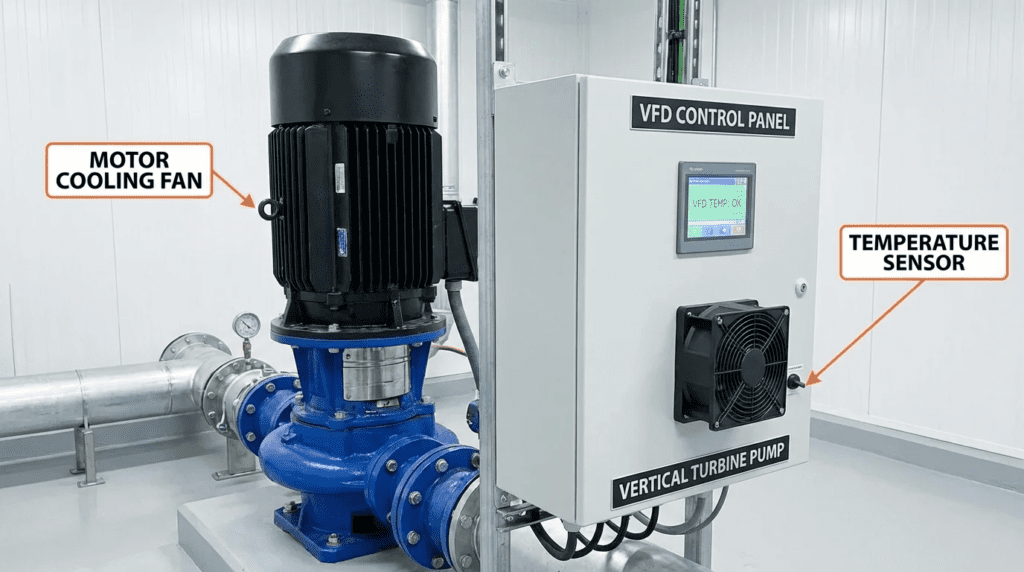
- Temperature Monitoring: Specify RTDs (Resistance Temperature Detectors) in both the motor windings (stator) and the thrust bearings. These should be hardwired to the VFD or PLC to trip the unit if thermal limits are exceeded.
- Flow Switches: A thermal dispersion flow switch on the discharge side ensures that the pump does not run against a closed valve (dead head), which is the fastest way to boil water in the bowl assembly and destroy the pump.
Maintainability, Safety & Access
Maintenance access directly impacts the likelihood of overheating issues being detected early.
- Lubrication Access: Vertical motors often have grease fittings at the top. Ensure these are accessible without removing VFD cabling. Automated greasing systems should be considered, but calibrated carefully—over-greasing causes churning and overheating just as under-greasing causes friction.
- Shroud Removal: Ensure that motor fan shrouds can be removed for cleaning without dismantling the entire motor, as clogged screens are a primary cause of stator overheating.
Lifecycle Cost Drivers
While VFDs are selected for energy savings (OPEX), the CAPEX of thermal protection is non-negotiable.
- Energy vs. Reliability: Running a VTP at extremely low speeds (e.g., 30 Hz) to “save energy” is often a false economy if it degrades the thrust bearing or requires auxiliary cooling fans that consume power.
- Replacement Costs: Vertical motors are generally 30-50% more expensive than horizontal equivalents and have longer lead times. Investing in advanced thermal protection (RTDs, vibration monitoring) pays back by preventing catastrophic failure.
COMPARISON TABLES
The following tables provide a structured comparison of motor enclosure types for vertical VFD applications and an application fit matrix. These tools assist engineers in selecting the appropriate configuration to manage thermal loads in various municipal and industrial scenarios.
| Enclosure Type | Cooling Mechanism | VFD Low-Speed Capability | Typical Applications | Thermal Limitations |
|---|---|---|---|---|
| WPI (Weather Protected Type I) | Open drip-proof with screens; internal fan creates airflow. | Poor. Cooling drops drastically below 45Hz unless oversized. | Clean, dry indoor pump rooms; line-shaft turbines. | Ingestion of dust/debris clogs windings, causing overheating. Not suitable for washdown. |
| WPII (Weather Protected Type II) | Complex airflow path removes moisture/dirt before entering motor. | Moderate. High inertia rotors help, but low-speed cooling is limited. | Outdoor vertical turbine pumps; raw water intakes. | Air passages can clog. High cost. Requires minimum speed strictly enforced. |
| TEFC (Totally Enclosed Fan Cooled) | External shaft-mounted fan blows air over finned frame. | Variable. 2:1 constant torque typical. Below 30Hz, cooling is negligible. | Wastewater, chemical feed, dusty environments. | Efficiency drops at low speeds due to windage. “Dirty” fins stop heat transfer. |
| TEAO (Totally Enclosed Air Over) | Relies on airflow from the driven fan or external blower. | Excellent (if blower equipped). Independent of motor speed. | Submersible VTPs (dry pit) or max-reliability specs. | Requires external power source for blower. Interlock required to prevent run without blower. |
| Scenario | Primary Thermal Risk | Recommended Motor Spec | Control Strategy | Relative Cost |
|---|---|---|---|---|
| Deep Well Potable Water | Thrust bearing failure at low speed (lack of oil wedge). | WPI with high-thrust bearings & RTDs. | Min Hz set by thrust bearing mfr (usually >30Hz). | Medium |
| Raw Water Intake (River/Lake) | Variable static head leading to dead-heading. | WPII with abrasion-resistant insulation. | Dynamic min speed setpoint based on level. | High |
| Booster Station (Inline) | Motor winding heat due to high ambient room temp. | TEFC with Class H Insulation. | Room ventilation interlocked with VFD run signal. | Low-Medium |
| Wastewater Lift Station | Clogging causing overload/heat; ragging. | TEFC Inverter Duty (10:1 CT) or Submersible. | Jam detection algorithm; de-ragging cycle. | High |
ENGINEER & OPERATOR FIELD NOTES
Specifications on paper often differ from reality in the field. The following section provides practical guidance for commissioning and maintaining Vertical Turbine VFD Setup: Preventing Overheating.
Commissioning & Acceptance Testing
The commissioning phase is the critical moment to verify thermal performance.
- Temperature Rise Test: Do not rely on the VFD display alone. During the Field Acceptance Test (FAT), run the pump at minimum speed, rated speed, and maximum speed for at least 4 hours each. Use an infrared camera to inspect the motor casing, conduit box connections, and thrust bearing housing. Any hotspot >10°C above the baseline warrants investigation.
- Resonance Mapping: Conduct a vibration sweep from minimum to maximum frequency. Look for spikes in vibration amplitude (displacement/velocity). If a resonance point is found (e.g., at 42 Hz), program a “Skip Frequency” with a bandwidth (e.g., 40-44 Hz) into the VFD to prevent the drive from dwelling at that thermal-generating speed.
- VFD Tuning: Ensure the Carrier Frequency is optimized. While higher carrier frequencies (e.g., 8-12 kHz) reduce audible motor noise, they increase heat generation in the VFD IGBTs and can create higher voltage spikes at the motor terminals. A setting of 2-4 kHz is typically preferred for large vertical motors to protect insulation, provided audible noise is acceptable.
Common Specification Mistakes
Engineers frequently overlook the interaction between VFDs and vertical mechanics.
- Ignoring Cable Length: Long motor leads (>100 ft) create reflected waves (voltage doubling) that degrade insulation. Specifications must require dV/dt filters or load reactors for long runs, and Sine Wave filters for runs exceeding 300-500 ft, to prevent winding overheating.
- Static Head Blindness: Specifying a VFD for a system that is 90% static head is a common error. The useful speed range might only be 55-60 Hz. Below 55 Hz, the pump produces zero flow, churning water and heating up. VFDs may not be the right choice for high-static, flat-curve applications.
O&M Burden & Strategy
Operational strategies must evolve when shifting from constant speed to VFD.
- Greasing Intervals: Heat degrades grease. If a motor runs hot (near its Class B limit), regreasing intervals should be shortened. Operators should monitor the discharged grease; darkened or liquefied grease indicates thermal breakdown.
- Filter Maintenance: For VFDs cooling fans and motor air intakes, filter cleaning schedules are paramount. A clogged filter on a VFD cabinet can cause the drive to derate or trip, while a clogged screen on a WP-II motor ensures winding overheating.
- Predictive Maintenance: utilize the VFD’s internal logic to monitor torque trends. A gradual increase in torque at a specific speed often indicates bearing wear or ragging before thermal alarms trip.
DESIGN DETAILS / CALCULATIONS
This section outlines the calculation methodologies and standards compliance required for a robust design.
Sizing Logic & Methodology
To prevent overheating, the minimum speed must be calculated based on both hydraulic and thermal constraints. The calculation logic follows three steps:
- Determine Hydraulic Minimum Speed:
Use the Affinity Laws, but correct for static head. The approximate zero-flow speed ($N_{min}$) can be estimated by:
$$ N_{min} = N_{rated} times sqrt{frac{H_{static}}{H_{shutoff}}} $$
Where $H_{static}$ is the system static head and $H_{shutoff}$ is the pump shut-off head at rated speed.
Add a safety margin (typically +5 Hz) to this result to ensure flow and cooling. - Determine Motor Thermal Minimum Speed:
Consult the motor manufacturer’s “Constant Torque” vs. “Variable Torque” speed range. For a standard TEFC vertical motor, the minimum speed for 1.0 Service Factor operation might be 30 Hz. - Determine Bearing Lubrication Minimum Speed:
Thrust bearings (Kingsbury type) typically require 100-200 RPM minimum to establish an oil wedge. Verify this corresponds to a Hz value lower than the hydraulic minimum.
The highest of these three values becomes the VFD Minimum Frequency parameter.
Specification Checklist
When writing specifications (Div 26 and Div 43), ensure the following are included to prevent Vertical Turbine VFD Setup: Preventing Overheating issues:
- Motor Spec: NEMA MG1 Part 31 compliance (Inverter Duty). Class F or H insulation with Class B rise. 1.15 Service Factor on Sine Wave, 1.0 Service Factor on VFD.
- Grounding: Shaft Grounding Ring (SGR) installed on the DE (Drive End) or NDE (Non-Drive End) to prevent bearing currents.
- Sensors: Min. 2 RTDs per phase (windings) and 1 RTD per bearing (thrust and guide).
- Testing: Reed Frequency (Critical Speed) analysis report submitted prior to fabrication.
- Cooling: If operating below 2:1 turndown continuously, require separate constant-speed blower cooling (TEAO/TEBC).
Standards & Compliance
Adherence to industry standards ensures legal and technical safety.
- NEMA MG1 Part 31: Definitive standard for motors operated on variable frequency drives. Ensures insulation can withstand voltage spikes of 1600V peak.
- AWWA E103: Standard for Horizontal and Vertical Line-Shaft Pumps. Reference this for vibration limits and mechanical integrity.
- IEEE 519: Standard for harmonic control. High harmonics (THD) cause excessive heating in motors and transformers. Specify Active Front End (AFE) drives or matrix filters if THD compliance is strict.
FAQ SECTION
What is the minimum speed for a vertical turbine pump on a VFD?
There is no single universal number, but it is typically between 30 Hz and 45 Hz. The minimum speed is dictated by the highest of three factors: the speed required to overcome static head (hydraulic limit), the speed required to spin the motor fan fast enough for cooling (thermal limit), or the speed required to maintain the thrust bearing oil film (mechanical limit). Engineers must calculate the intersection of the system curve and the pump curve to find the zero-flow point and set the VFD minimum at least 5-10% above that.
Why do VFDs cause vertical motors to overheat more than horizontal motors?
Vertical motors (especially TEFC types) often rely on fans connected directly to the motor shaft. Because vertical motors are often placed in hot, stagnant locations (like top floors of pump stations) and are subject to high thrust loads, the reduction in cooling airflow at low speeds is more critical than in horizontal applications. Additionally, vertical motors are structural cantilevers, making them more susceptible to VFD-induced resonance, which generates heat through vibration and friction.
Do I need an “Inverter Duty” motor for vertical turbine applications?
Yes, absolutely. NEMA MG1 Part 31 “Inverter Duty” motors are designed with higher quality insulation systems capable of withstanding the voltage spikes (dV/dt) caused by VFD switching. Standard motors may suffer insulation breakdown and winding failure due to the thermal and electrical stresses of VFD operation. For vertical turbines, specifying Inverter Duty also ensures the bearings are rated for the potential electrical discharge currents.
What is the Reed Frequency and why does it matter for overheating?
The Reed Frequency is the natural resonant frequency of the vertical motor and pump structure. If the VFD operates the pump at this specific frequency, the vibration amplitude increases dramatically. This vibration causes excessive friction in the bearings and couplings, generating rapid heat and leading to mechanical seal failure or bearing seizure. A critical speed analysis identifies this frequency so it can be programmed out of the VFD’s operating range.
How does carrier frequency affect vertical motor temperature?
The VFD carrier frequency (the rate at which the DC bus switches on and off) affects both motor noise and heat. A higher carrier frequency (e.g., 10 kHz) reduces audible noise but increases heat in the VFD. A lower carrier frequency (e.g., 2 kHz) runs the VFD cooler but sends “rougher” power to the motor, which can slightly increase motor heating and audible whine. For vertical pumps, a balance (typically 2-4 kHz) is selected to minimize voltage spikes at the motor terminals while managing thermal loads.
Can I retrofit a VFD to an existing vertical turbine pump?
Retrofitting is possible but risky without analysis. Old vertical motors (Class B insulation) may not survive VFD voltage spikes. Additionally, the existing pump might have a critical speed within the new variable operating range. It is recommended to replace the motor with an Inverter Duty model and install shaft grounding rings. If keeping the old motor, install a load reactor or dV/dt filter to protect the insulation and strictly limit the turndown ratio.
CONCLUSION
Key Takeaways for Engineers
- Calculate, Don’t Guess: Determine minimum speed based on Static Head, Motor Cooling, and Bearing Lubrication requirements.
- Manage Resonance: Require a Critical Speed (Reed Frequency) analysis and program “Skip Frequencies” in the VFD.
- Protect the Motor: Specify NEMA MG1 Part 31 Inverter Duty motors with Class H insulation and Shaft Grounding Rings.
- Monitor Thermals: Mandate RTDs in windings and thrust bearings, hardwired to trip the VFD.
- Watch the Flow: Ensure VFD programming prevents operation below the Minimum Continuous Stable Flow (MCSF) to avoid recirculation heating.
Successfully implementing a Vertical Turbine VFD Setup: Preventing Overheating requires a departure from standard horizontal pump specifications. The vertical orientation introduces structural dynamics, thrust loading, and cooling constraints that are unforgiving of generic design choices. By treating the pump, motor, and drive as an integrated thermal system—rather than isolated components—engineers can realize the energy benefits of variable speed without sacrificing reliability.
When designing these systems, always prioritize thermal headroom over extreme turndown ratios. A pump that runs reliably at 40-60 Hz offers far better lifecycle value than one pushed to run at 20 Hz that fails within two years. Through rigorous specification of materials, validation of critical speeds, and implementation of active monitoring, utilities can ensure their vertical pumping infrastructure operates coolly and efficiently for decades.