
Primary Treatment of Wastewater: Sedimentation, Clarification & DAF
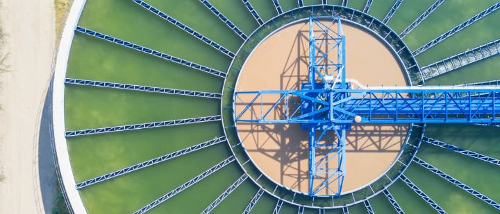
Efficient sedimentation processes are essential for both municipal and industrial wastewater treatment facilities. As raw wastewater enters the treatment plant, it undergoes initial screening before proceeding to sedimentation tanks where the separation process begins. This stage is pivotal for the protection of downstream treatment units and for minimizing the potential for damage or additional processing costs. Moreover, understanding the principles that govern sedimentation allows for effective design, operation, and maintenance of settling tanks, optimizing their performance and ensuring that water released into the environment complies with regulatory standards.
Gravity separation appears at more than one point in a treatment plant, and the same physical principles govern each appearance even though the equipment, loading criteria, and failure modes differ considerably. Primary clarifiers separate raw settleable solids ahead of biological treatment; secondary clarifiers separate biological floc and return it to the process; high-rate settlers and flotation units achieve separation in a fraction of the footprint. This guide serves as the master reference for that full range of solids-liquid separation practice, with the Subcategory Overview below mapping each discipline to its dedicated resource.
Key Takeaways
- Sedimentation is a gravity-based process essential for removing particulates from wastewater.
- The design and operation of sedimentation tanks are critical for the overall effectiveness of water treatment.
- Regular maintenance is important for performance optimization and problem prevention in sedimentation stages.
Subcategory Overview: Solids-Liquid Separation
Separation practice divides into three areas: the underlying principles that predict how a given suspension will behave, the clarifier types that apply those principles at different points in the treatment train, and the high-rate and alternative technologies that achieve the same separation in less space or against suspensions that will not settle at all.
Principles and Fundamentals
Before selecting a basin or a mechanism, the engineer needs to know which settling regime governs the suspension in question, because the design criterion changes with the regime.
Sedimentation
Sedimentation is the gravity-driven separation of particles denser than the surrounding water, and it is the most widely applied unit operation in water and wastewater treatment because it requires no energy input beyond what moves the water. The process removes a substantial share of suspended solids and, with them, a meaningful fraction of the organic load, which is why it appears both ahead of and behind biological treatment. Performance depends on particle characteristics, basin hydraulics, and residence time, and the practical limit is set not by the physics of settling but by the difficulty of achieving quiescent, evenly distributed flow across a large basin. Understanding what sedimentation can and cannot accomplish is the starting point for every separation decision downstream of it.
Settling Theory
Settling theory describes four distinct regimes, and applying the wrong one is a common source of design error. Discrete settling governs dilute suspensions of non-flocculating particles such as grit, where each particle settles independently at a velocity predicted by Stokes’ law or its turbulent-regime equivalents. Flocculent settling applies where particles agglomerate during descent, so settling velocity increases with depth and column testing rather than calculation is required. Zone settling governs concentrated suspensions such as mixed liquor, where the mass subsides as a blanket with a defined interface, and compression settling governs the thickening layer at the basin floor. A primary clarifier is designed against flocculent settling; a secondary clarifier is designed against zone settling, which is why their loading criteria differ so sharply.
Clarifier Types
Clarifiers differ by position in the treatment train and by geometry, and both distinctions carry real design consequences.
Primary Clarifiers
Primary clarifiers remove settleable raw solids ahead of biological treatment, typically achieving 50 to 70 percent suspended solids removal and 25 to 40 percent BOD removal. Surface overflow rates commonly fall in the 800 to 1,200 gpd/ft² range at average flow with detention times of roughly 1.5 to 2.5 hours, and the governing criterion is surface overflow rate rather than solids loading because the influent is comparatively dilute. Removal in a primary clarifier translates directly into reduced aeration demand downstream, which makes it one of the more energy-efficient interventions available in a plant. Sludge withdrawal frequency matters more than operators often expect, since primary sludge turns septic quickly and releases odor and soluble organics back into the flow.
Secondary Clarifiers
Secondary clarifiers perform two functions simultaneously that are frequently in tension: clarifying the effluent and thickening the return activated sludge. Because mixed liquor settles in the zone regime, solids loading rate rather than surface overflow rate usually governs the design, and a basin that appears comfortable on overflow rate can be badly overloaded on solids. Sludge settleability, expressed through the sludge volume index, is the operating variable that most affects performance, and a filamentous bulking event will overwhelm a properly sized clarifier without any change in flow. Flocculating center wells, adequate sidewater depth, and careful energy dissipation at the inlet contribute more to performance than incremental surface area.
Wastewater Clarifiers
Wastewater clarifiers come in several floor geometries, of which the hopper-bottom design is the most distinctive. A steeply sloped conical or pyramidal floor, typically at 50 to 60 degrees, concentrates settled solids at a central point by gravity alone, eliminating the scraper mechanism entirely. That absence of moving parts in the sludge zone is the design’s main appeal, making it well suited to small plants, package units, and installations where mechanism maintenance would be difficult. The trade-off is depth: achieving the required slope across any significant diameter drives excavation and structural cost sharply upward, which is why hopper-bottom units are rarely economical above modest diameters.
Rectangular Clarifiers
Rectangular clarifiers route flow horizontally from an inlet channel across the basin length to effluent weirs at the far end, with chain-and-flight or traveling bridge collectors moving sludge to a hopper. Their principal advantage is spatial efficiency: units share common walls, so a bank of rectangular basins occupies substantially less land than circular units of equal area, which matters at constrained sites. Length-to-width ratios of roughly 4:1 or greater help approximate plug flow and limit short-circuiting. The trade-off is that flow distribution across the inlet width is harder to achieve than the radial distribution of a circular unit, and inlet baffling deserves careful attention rather than a standard detail.
High-Rate and Alternative Separation
Where footprint is constrained or the suspension resists gravity settling, a different class of technology applies the same separation objective by other means.
Lamella Clarifiers
Lamella clarifiers are complete settling units built around a pack of inclined plates, typically set at 55 to 60 degrees, which multiply effective settling area within a compact tank. Because a particle need only fall the short distance to the plate above it rather than to the basin floor, the projected horizontal area of the plate pack can be five to ten times the tank footprint, allowing a unit to replace a conventional basin many times its size. The inclination allows collected solids to slide down the plates into a hopper below without mechanical assistance. Their limitation is sensitivity to solids loading and to grease, either of which will foul the pack and progressively destroy the area advantage that justified the technology.
Plate Settlers
Plate settlers, along with tube settler modules, are most often deployed as retrofit inserts placed into existing conventional basins rather than as complete new units. Dropping a module bank into an underloaded or overloaded rectangular basin can raise its effective capacity by a factor of two or three without new tankage, which makes this among the least expensive capacity upgrades available to a constrained plant. Success depends on flow distribution beneath the modules, since a bank fed unevenly will short-circuit through the least-resistant path and deliver a fraction of its theoretical benefit. Cleaning access and a defined program for periodic module washing should be established during design rather than improvised later.
Dissolved Air Flotation
Dissolved air flotation inverts the separation direction, saturating a recycle stream with air under pressure and releasing it into the basin so that microbubbles attach to particles and carry them upward to a float layer. The approach is the right answer wherever solids are neutrally buoyant, oily, or otherwise unwilling to settle, which covers fats, oils, and grease, algae, fibrous industrial solids, and light biological floc. The air-to-solids ratio is the governing design parameter, along with hydraulic loading rate and recycle percentage. Because performance depends on bubble attachment rather than density difference, DAF frequently succeeds on suspensions where no amount of additional settling area would help.
Clarifier Equipment Manufacturers
Evaluating clarifier equipment manufacturers is an engineering exercise centered on the mechanism rather than the tank, since the concrete will outlast several generations of the equipment inside it. Specifications should state the collector torque rating explicitly, along with the overload and cutout settings, because torque capacity determines whether a mechanism survives a heavy sludge blanket or shears a component. Drive type, materials in the submerged zone, bearing arrangement, and the availability of a mechanism that can be serviced without dewatering the basin all deserve attention. Service network coverage and parts lead time matter over a thirty-year asset life, and a mechanism idle for weeks awaiting a part is a clarifier out of service.
Sedimentation Principles
Sedimentation is an essential process in wastewater treatment, employing gravity to remove suspended particles. Effective sedimentation depends on various settling behaviors, with each behavior pivotal in designing and operating the treatment facilities.
Discrete Settling
In discrete settling, individual particles descend independently, unaffected by the presence of other particles. This occurs when particles are well-separated and have a high enough density relative to the water, prompting a downward trajectory to be followed without disturbances. Typical of sand and grit removal, the design considers particle size and density.
Flocculent Settling
During flocculent settling, particles come together to form flocs, which collectively settle faster than individual particles. This behavior is dependent on particle collision and adhesion. Chemicals like polymers are often added to promote floc formation, enhancing sedimentation efficiency. Because settling velocity increases as a particle descends and collects others, flocculent settling cannot be predicted by calculation alone and is characterized instead through settling column tests at multiple depths.
Zone Settling
Zone settling happens when a concentration of particles settles as a mass, leading to a distinct interface between the clear liquid above and the sludge below. The settling velocity of this zone is determined not by individual particle characteristics but by the concentration of the entire mass and the inter-particle forces. This is the regime that governs secondary clarifier design, which is why solids loading rate rather than surface overflow rate is normally the controlling criterion for those basins.
Compression Settling
Lastly, compression settling occurs when particles at the bottom of the sedimentation tank are pressed together under the weight of the overlaying sludge, resulting in water being pushed out from the spaces between them. The mechanical characteristics of sludge, particularly its compressibility and permeability, are factored into this settling phase.
Purpose and Goals of Sedimentation
Sedimentation in wastewater treatment serves a primary function: the separation of solid particulate matter from wastewater. This process relies on gravity to remove suspended solids and is integral to the treatment sequence. Sedimentation units broadly aim to achieve clarity in water and reduce downstream treatment loads.
- Clarification: The foremost goal is to achieve clarity of effluent. By allowing particles to settle, sedimentation tanks greatly increase the transparency and quality of water.
- Load Reduction: Sedimentation significantly reduces the biological and chemical demand on subsequent treatment processes by removing a substantial volume of the solids load from the wastewater stream.
Application: During sedimentation, solid particles with greater density than water descend and accumulate at the bottom of the tank. This gathered material, commonly termed sludge, is later removed and further processed or disposed of.
Efficiency: Sedimentation aims at high efficiency to minimize the volume of solids entering secondary treatment phases like biological oxidation. This is not only for protecting sensitive biological processes but also for limiting operation and maintenance costs.
Effective sedimentation relies on carefully designed tanks that provide conditions for optimal settling. Parameters such as detention time, tank depth, and flow velocity are fine-tuned to ensure that the maximum possible amount of suspended solids is removed before the water moves to the next treatment phase.
In summary, the purpose of sedimentation in water treatment is twofold: to produce clearer effluent water and to prevent excessive loads on further processing steps. These goals underscore the fundamental role sedimentation plays in the overall wastewater treatment paradigm.
Processes of Water Treatment
The treatment of wastewater is a multi-stage process designed to remove contaminants and solids, increasing water purity. Understanding the flocculation and sedimentation water treatment, alongside clarification, provides insight into how these steps are essential for safe and clean water.
Flocculation Process
In the Flocculation Process, chemicals referred to as flocculants are added to the water, enabling particles to coalesce into larger aggregates or flocs. This step enhances the efficiency of sedimentation by increasing particle size, making it easier for solids to settle out of the water.
Sedimentation Process
Sedimentation Process involves the settling of suspended particles from the water. As the water flows through large tanks at a reduced speed, gravity pulls the heavier floc particles down to the bottom, which is then collected as sludge, while the cleaner water moves to the next phase.
Clarification Process
The Clarification Process is aimed at further clearing the water. After sedimentation, the water contains fewer particles and is passed through a clarifier. Here, any remaining solids settle at the bottom, and some sites utilize mechanical scrapers to assist in removing sludge, while the clear water at the top proceeds to the next treatment stage.
Types of Sedimentation Tanks
Wastewater treatment processes often include sedimentation, whereby suspended solids separate from water by gravity. The design of sedimentation tanks varies according to the specific needs of the treatment process. There are several common types:
Primary Sedimentation Tanks
Traditionally, these tanks are the first stage in the sedimentation process. They focus on removing raw sewage solids before biological treatment. It’s common to see two subtypes in this category:
- Rectangular Tanks: where water flows horizontally through a long tank.
- Circular Tanks: featuring a center feed and radial flow.
Secondary Sedimentation Tanks
These tanks are used after biological treatment, removing further suspended solids and biological floc. They also prevent the loss of biological solids from the system. Their configurations often mirror the primary tanks’ design.
Clarifiers
Functioning similarly to sedimentation tanks, clarifiers may be used in both the primary and secondary stages. They are equipped with mechanical devices for continuous removal of settled solids and come in different forms:
- Horizontal Flow: solids settle in a basin while clarified water exits out the top.
- Solid Contact Clarifiers: combine mixing, flocculation, and sedimentation in a single unit.
- Tube Settlers and Plate Clarifiers: enhance settling by reducing the vertical distance solids must fall.
Each sedimentation approach and tank design serves a specific function in the treatment of wastewater. Particle size, wastewater flow rates, and treatment objectives are crucial factors in determining the appropriate choice of sedimentation tank.
Selection and Specification Framework
Clarifier selection and sizing follow a fixed sequence, and the most common failure is applying the criterion appropriate to one settling regime to a basin governed by another.
Step 1: Identify the Governing Settling Regime
The regime determines the design criterion. Grit and other dilute non-flocculating suspensions settle discretely and are designed against particle settling velocity. Raw wastewater solids in a primary clarifier settle flocculently, so surface overflow rate governs and column testing informs the removal expectation. Mixed liquor in a secondary clarifier settles in the zone regime, so solids loading rate normally governs and the sludge volume index becomes the critical operating variable. Applying primary clarifier overflow rates to a secondary basin, or ignoring solids loading because overflow rate appears comfortable, produces basins that fail under exactly the conditions they were meant to handle.
Step 2: Size Against Both Criteria and Take the Larger
A secondary clarifier must satisfy surface overflow rate and solids loading rate simultaneously, at both average and peak conditions, and the controlling criterion shifts with mixed liquor concentration. This means the clarifier cannot be sized independently of the biological process it serves: a decision to operate at higher MLSS for nitrification directly loads the clarifier, and a basin adequate at 3,000 mg/L may be overloaded at 4,000 mg/L with no change in flow whatever.
Step 3: Work the Calculation
A worked example makes the interaction explicit.
Area: Each basin is π × 35² ≈ 3,848 ft², giving 7,697 ft² total.
Surface overflow rate: At average flow, 4,000,000 ÷ 7,697 ≈ 520 gpd/ft². At peak hour, 8,000,000 ÷ 7,697 ≈ 1,039 gpd/ft². Both sit within conventional secondary clarifier ranges, so on this criterion the basins look comfortable.
Solids loading rate: Total solids-bearing flow is influent plus return, or 4.0 + 2.0 = 6.0 MGD at average. SLR = 6.0 × 3,000 × 8.34 ÷ 7,697 ≈ 19.5 lb/day/ft², within the typical average-condition range. At peak hour with return scaling proportionally, total flow is 12.0 MGD and SLR = 12.0 × 3,000 × 8.34 ÷ 7,697 ≈ 39.0 lb/day/ft², still below the customary peak ceiling near 50.
The MLSS sensitivity: Raise MLSS to 4,000 mg/L to support nitrification and nothing about the flow changes, but SLR becomes 26.0 lb/day/ft² at average and 52.0 lb/day/ft² at peak — now above the customary limit. The clarifier has been overloaded by a decision made in the aeration basin.
Detention time: Basin volume is 7,697 × 14 ≈ 107,760 ft³, or about 806,000 gallons, giving roughly 4.8 hours at average flow and 2.4 hours at peak hour.
That MLSS sensitivity is the single most useful thing to carry away from a clarifier calculation. Secondary clarifiers are loaded by the biological process as much as by the flow, and plants that raise MLSS to solve one problem frequently create another at the clarifier.
Step 4: Attend to Depth, Inlet Energy, and Weir Placement
Surface area receives most of the design attention and is rarely the whole story. Sidewater depth provides the volume for sludge blanket storage during peak events, and shallow basins lose solids over the weir at flows that a deeper basin of identical area would handle without difficulty; depths of 12 to 16 ft are common in modern secondary clarifier design. Inlet energy dissipation and a properly sized flocculating center well determine whether flow distributes evenly or short-circuits across the surface. Weir placement matters as well, since weirs set too near the wall draw the upward density current directly into the effluent.
Step 5: Specify the Mechanism to the Duty
The tank outlasts the mechanism by decades, so mechanism specification carries disproportionate long-term weight. Collector torque rating should be stated explicitly along with overload alarm and cutout settings, since torque capacity determines survival of a heavy blanket rather than merely nominal performance. Submerged materials, bearing arrangement, and drive type should suit a continuously wetted, corrosive environment. Where possible, select a mechanism whose principal wear components can be serviced without dewatering the basin, because taking a clarifier out of service is a plant capacity event rather than a routine maintenance task.
Separation Technology Comparison
| Technology | Separation Mechanism | Governing Criterion | Best-Fit Applications | Key Limitations | Footprint |
|---|---|---|---|---|---|
| Primary Clarifiers | Gravity, flocculent settling | Surface overflow rate | Raw solids removal ahead of biology | Septicity if sludge withdrawal lags | Large |
| Secondary Clarifiers | Gravity, zone settling | Solids loading rate | Biological floc separation and RAS thickening | Sensitive to sludge settleability and MLSS | Large |
| Rectangular Clarifiers | Horizontal flow, gravity | Overflow rate, length-to-width ratio | Constrained sites, common-wall construction | Inlet distribution across width | Efficient in banks |
| Hopper Bottom Clarifiers | Gravity with sloped floor collection | Overflow rate, floor slope | Small plants, package units | Depth and excavation cost at larger diameters | Small diameter, deep |
| Lamella Clarifiers | Inclined plate, reduced settling distance | Projected plate area loading | Compact new installations | Grease and solids fouling of the pack | Very compact |
| Plate Settler Modules | Inclined plate inserts in existing basins | Projected area, flow distribution | Capacity uprating without new tankage | Short-circuiting if feed is uneven | Retrofit, no new area |
| Dissolved Air Flotation | Bubble attachment, upward separation | Air-to-solids ratio, hydraulic loading | FOG, algae, light or buoyant solids | Recycle energy, saturator maintenance | Compact |
| Regime | Typical Suspension | Behavior | Design Criterion |
|---|---|---|---|
| Discrete | Grit, sand, dilute inorganics | Particles settle independently at constant velocity | Particle settling velocity |
| Flocculent | Raw wastewater solids, coagulated water | Particles agglomerate and accelerate with depth | Surface overflow rate, column test data |
| Zone | Mixed liquor, thickener feed | Mass subsides as a blanket with a clear interface | Solids loading rate, SVI |
| Compression | Sludge blanket at basin floor | Water expressed by overlying weight | Blanket depth and residence time |
Wastewater Treatment Applications
In the realm of wastewater management, sedimentation is an essential process that serves as a preliminary or secondary phase in the treatment sequence. Sedimentation in wastewater treatment leverages gravity to separate suspended solids from water, enhancing the overall quality of the effluent.
Preliminary Treatment
Primarily, sedimentation functions as a pre-treatment method where it removes large particulates. This initial phase typically operates in conjunction with screening devices, and its main goal is to prepare wastewater for subsequent treatment stages.
Primary Sedimentation
Following pre-treatment, wastewater undergoes primary sedimentation. Here, solid particles settle out as sludge at the bottom of sedimentation tanks, and skimmers remove floating material such as oils and greases. This step significantly reduces the biological load before the effluent progresses to the biological treatment stages.
Secondary Treatment
Secondary sedimentation occurs after biological processes such as activated sludge or trickling filters. It allows for the removal of bio-solids that have aggregated as a result of biological activity. The US EPA provides detailed guidelines on the uses and design of sedimentation processes within wastewater treatment systems, ensuring the safe discharge of treated water or its reuse.
It is widely acknowledged that the appropriate design and operation of sedimentation tanks are pivotal for efficient wastewater treatment. They must be tailored to the specific characteristics of the wastewater and the desired quality of discharge, as specified by regulations and environmental standards.
Design and Operation of Settling Tanks
Settling tanks, also known as sedimentation tanks, play a crucial role in the wastewater treatment process. Their design is optimized to allow solids to settle out of the water column, clarifying the effluent and reducing the load in subsequent treatment stages.
Key Design Parameters:
- Dimensions: The tanks are typically rectangular or circular, with their size depending on the volume of wastewater being treated.
- Flow Rate: Designed to minimize turbulence, ensuring that the incoming flow does not disturb the settled sludge.
- Detention Time: Sufficient time must be allowed for the solids to settle. This is typically calculated based on the characteristics of the wastewater and the expected load.
- Sidewater Depth: Depth provides storage volume for the sludge blanket during peak flow events, and shallow basins lose solids over the weir at flows a deeper basin of equal area would handle.
- Weir Loading Rate: Weir length and placement affect the upward density current near the wall, and weirs set too close to the perimeter draw solids directly into the effluent.
Operational Considerations:
- Sludge Removal: Sludge that accumulates at the bottom of the tank is usually removed by mechanized scrapers or pumps for further treatment.
- Scum Collection: Floating materials are skimmed from the surface to prevent them from exiting the tank with the treated effluent.
Performance Monitoring:
- Regular Inspection: Settling tanks should be inspected frequently to ensure they are operating correctly.
- Effluent Quality: The clarity of the effluent is an indicator of sedimentation performance and should be monitored.
- Sludge Blanket Depth: Direct measurement with a blanket detector gives earlier warning of an impending solids loss than effluent turbidity, which only responds once solids are already leaving.
Types of Settling Tanks:
- Primary Settling Tanks: Remove solids before the biological treatment process.
- Secondary Settling Tanks: Allow biological flocs to settle after the aeration process.
Each type has variations in design to improve efficiency, such as lamella plates in secondary tanks to increase the settling area. Operators must ensure the smooth functionality of these systems to guarantee effective wastewater treatment.
Efficiency and Performance Optimization
In the realm of wastewater treatment, sedimentation is a pivotal process where the efficiency can significantly determine the overall effectiveness of water treatment. Operators endeavor to optimize both the design and operational aspects to enhance sedimentation process performance.
- Design Factors: Appropriate design can accommodate a wide range of wastewater flow rates and characteristics. Parameters such as tank geometry, depth, and retention time are meticulously calculated to facilitate the settling of particles. The introduction of components like baffles can direct flow and reduce turbulence, resulting in increased settling efficiency.
- Chemical Aids: The use of chemical coagulants and flocculants is a common practice to agglomerate fine particles into larger settleable flocs. This improves the sedimentation speed and efficiency. Decisions regarding the type and dosage of chemicals are made based on the wastewater characteristics and desired outcomes.
- Maintenance Practices: Regular desludging and cleaning of sedimentation tanks are essential to prevent the accumulation of settled solids, which could hinder the process and reduce the system’s capacity.
- Monitoring: Continuous monitoring of influent and effluent quality, as well as sludge volume, ensures that the system operates within optimal parameters. It can help identify inefficiencies early on and necessitate adjustments to the process.
By emphasizing these aspects, facilities can ensure their sedimentation processes are not only efficient but also economically and environmentally sound. It is a given that ongoing research and advancements will continue to bolster the effectiveness of sedimentation in wastewater treatment.
One optimization deserves separate mention because it costs nothing. Density currents driven by the temperature and solids concentration difference between influent and basin contents are the dominant hydraulic inefficiency in most large clarifiers, routinely reducing effective volume well below the nominal figure. Peripheral baffles, sometimes called Stamford or McKinney baffles, redirect the upward current away from the effluent weir and have produced measurable improvements in effluent solids at many plants for a modest retrofit cost. Dye or drogue testing will identify whether short-circuiting is occurring before any money is spent.
Maintenance and Troubleshooting
Proper maintenance of sedimentation tanks in wastewater treatment is vital for efficient operation. Regular inspections can identify issues such as sludge accumulation, surface scum, or mechanical failures. Facilities should implement a consistent maintenance schedule that includes:
- Sludge Removal: Accumulated sludge should be removed regularly to prevent septic conditions and to maintain tank capacity.
- Surface Skimming: Scum and floating debris need to be skimmed off to prevent clogging and to maintain an effective surface area for sedimentation.
When troubleshooting common problems within sedimentation tanks, operators may encounter issues like:
- Poor Settling: This can be due to high flow rates, turbulence, or inadequate detention time. Operators might need to adjust inflow or check for mixers’ malfunctions.
- Odors: These often result from anaerobic conditions due to excess sludge buildup. Regular sludge removal can mitigate this issue.
In the case of mechanical maintenance:
- Inspect and maintain weirs and baffles for effective flow distribution.
- Check and lubricate moving parts periodically to ensure they are functioning correctly.
Troubleshooting operations should be systematic. An initial assessment should be followed by these steps:
- Investigate any changes in influent characteristics.
- Examine operational controls, such as flow rate and detention times.
- Check for mechanical failures or malfunctions in components like scrapers or pumps.
- Assess the sludge removal process to ensure it is performed adequately.
Operators must document maintenance and troubleshooting efforts thoroughly for regulatory compliance and future reference.
Field Notes
The observations below recur across clarifier installations regardless of geometry or position in the treatment train.
Commissioning Considerations
Clarifier commissioning should include a level survey of the effluent weirs before the basin is put into service, because weirs out of level by even a fraction of an inch draw disproportionate flow at the low point and short-circuit the basin permanently. Mechanism torque should be verified against the specified rating rather than accepted from documentation, and the overload alarm and cutout settings confirmed by test rather than by nameplate. A dye or drogue test at design flow establishes the actual hydraulic residence time against the theoretical figure, and the difference is frequently substantial enough to change operating expectations. Sludge withdrawal rates and blanket detection instrumentation should be calibrated before the basin carries real load.
Common Specification Mistakes
Several errors appear repeatedly. Secondary clarifiers are sized on surface overflow rate alone, so a basin comfortable on that criterion is badly overloaded on solids loading at the MLSS the plant actually runs. Sidewater depth is minimized to save excavation cost, leaving no blanket storage volume during peak events. Weirs are placed at the perimeter wall without a peripheral baffle, drawing the upward density current straight into the effluent. Collector torque is specified by reference to a manufacturer’s standard rather than to the expected blanket condition. Firm capacity is defined without the largest basin out of service, so routine mechanism maintenance becomes a plant capacity event. Inlet energy dissipation is treated as a standard detail rather than as a design calculation.
Pro Tip
Before adding clarifier capacity, check the weir levels and run a dye test. Density currents and out-of-level weirs routinely reduce a basin’s effective volume to a fraction of its nominal figure, and both are correctable for a small fraction of the cost of new tankage. A peripheral baffle retrofit and a weir releveling have solved effluent solids problems at plants that were preparing to build an additional clarifier. The diagnostic costs a day of staff time and a bottle of dye, and it either identifies a cheap fix or confirms that the capacity is genuinely needed. Either outcome is worth having before a capital decision.
Operations and Maintenance Across Clarifier Types
Maintenance demand varies by geometry and mechanism. Circular clarifiers concentrate attention on the center drive, its torque overload protection, the rake arms, and the squeegees, with the drive being the component whose failure takes the basin out of service. Rectangular basins with chain-and-flight collectors add chain wear, flight replacement, and sprocket alignment, all of which occur below water and require dewatering. Traveling bridge collectors shift maintenance above water, which is an advantage, but add rail alignment and drive trolley upkeep. Hopper-bottom units eliminate the mechanism entirely and with it most of this burden, which is precisely their appeal at small scale. Across all types, weir cleaning and skimmer function receive less attention than they deserve relative to their effect on effluent quality.
Troubleshooting by Symptom
Most clarifier problems resolve to a short list of causes. Rising effluent solids with a stable flow and MLSS usually indicates deteriorating sludge settleability, and a sludge volume index trend plus a microscopic examination will identify filamentous bulking before the effluent tells you. A rising sludge blanket points to inadequate withdrawal rate rather than to a settling problem, and comparing RAS rate against solids balance distinguishes the two. Solids appearing at one sector of a circular basin or one side of a rectangular basin indicates a hydraulic distribution problem, most often out-of-level weirs or a damaged inlet baffle. Rising and floating sludge in patches usually signals denitrification in the blanket, releasing nitrogen gas, which points back to blanket residence time rather than to clarifier hydraulics.
Common Mistake
Treating the secondary clarifier as independent of the biological process it serves. Solids loading rate depends on mixed liquor concentration and return rate, not on influent flow alone, so a decision made in the aeration basin to raise MLSS for nitrification directly loads the clarifier, and a basin adequate at 3,000 mg/L can be overloaded at 4,000 mg/L with no change in flow whatever. Sludge settleability compounds this, since a filamentous bulking event will overwhelm a correctly sized clarifier that has never seen a hydraulic overload. Clarifier capacity is a property of the biological system as a whole, and evaluating it without the aeration basin operating conditions produces a number that means very little.
Design Details and Standards
Sizing Methodology Overview
Clarifier sizing proceeds from the governing settling regime rather than from a single loading figure. For a primary clarifier, establish design flows, apply a surface overflow rate appropriate to the expected removal, and confirm detention time and weir loading. For a secondary clarifier, calculate surface overflow rate and solids loading rate at both average and peak conditions using the design mixed liquor concentration and return rate, then size against whichever criterion controls. Sidewater depth follows from blanket storage requirements during peak events rather than from a minimum standard. Basin count follows from firm capacity with the largest unit out of service, and mechanism torque is specified against the expected blanket condition rather than against nominal duty.
Key Parameters by Application
The governing parameters differ across applications. Primary clarifiers are characterized by surface overflow rate, detention time, weir loading rate, and expected TSS and BOD removal. Secondary clarifiers are characterized by solids loading rate, surface overflow rate, sludge volume index, return rate, sidewater depth, and blanket depth. High-rate settlers are characterized by projected plate area, plate spacing and angle, and the hydraulic loading based on projected rather than footprint area. Dissolved air flotation is characterized by air-to-solids ratio, hydraulic loading rate, recycle percentage, and saturator pressure. Applying a parameter set from one application to another is a persistent source of design error.
Applicable Standards and References
Design practice in the United States draws on the Recommended Standards for Wastewater Facilities, commonly known as the Ten States Standards, which specify surface overflow and weir loading criteria, minimum sidewater depths, and redundancy provisions for settling tanks, and which many state agencies adopt directly or by reference. The Water Environment Federation Manual of Practice series provides the detailed engineering basis, with clarifier design and secondary clarifier performance treated at length, and the WEF and ASCE joint design manuals remain the standard references for settling column testing and solids flux analysis. Discharge obligations derive from the Clean Water Act through the National Pollutant Discharge Elimination System permit program administered by the U.S. Environmental Protection Agency. Analytical methods for suspended solids, settleable solids, and sludge volume index follow Standard Methods for the Examination of Water and Wastewater and 40 CFR Part 136. Mechanism and structural components are governed by ANSI, ASME, and ASTM standards, with drive torque ratings commonly specified against manufacturer test protocols that should be named explicitly in the specification.
Specification Checklist
- Identify the governing settling regime and select the design criterion that follows from it.
- Establish design flows for average, maximum month, and peak hour conditions separately.
- For secondary clarifiers, state the design MLSS and return rate explicitly, since both drive solids loading.
- Calculate surface overflow rate and solids loading rate at average and peak, and size against the controlling criterion.
- Test sensitivity to elevated MLSS, since biological process decisions load the clarifier directly.
- Set sidewater depth from blanket storage requirements during peak events, not from a minimum standard.
- Verify weir loading rate and place weirs away from the perimeter wall or provide a peripheral baffle.
- Calculate inlet energy dissipation and size the flocculating center well rather than adopting a standard detail.
- Specify collector mechanism torque rating with overload alarm and cutout settings stated.
- Select a mechanism whose principal wear components can be serviced without dewatering where possible.
- Define firm capacity with the largest basin out of service.
- Provide sludge blanket detection instrumentation and define the withdrawal control strategy.
- Include provisions for dye or drogue testing at commissioning and a weir level survey.
- Develop a present worth comparison across candidate configurations including mechanism replacement over the tank’s service life.
Frequently Asked Questions
What are the primary stages involved in wastewater treatment, and where does sedimentation fit in?
In wastewater treatment, the primary stages are preliminary, primary, secondary, and tertiary treatment. Sedimentation is a part of the primary treatment phase where suspended solids settle out of wastewater due to gravity.
Which chemicals are commonly used during the sedimentation stage of water treatment?
During the sedimentation stage, chemicals like aluminum sulfate (alum), ferric sulfate, ferric chloride, and sometimes polymers are used to facilitate the removal of suspended particles.
How do various types of sedimentation techniques differ in their application to wastewater treatment?
Sedimentation techniques in wastewater treatment vary mainly by the system's design. Gravity sedimentation is most common, but others include lamella plate sedimentation which increases the effective surface area for settling and dissolved air flotation where air bubbles carry solids to the surface.
Can you explain the differences between sedimentation, flocculation, and settling in wastewater treatment processes?
Sedimentation is the process by which particles settle to the bottom. Flocculation is the aggregation of particles into larger clusters or flocs to settle more effectively. Settling is a broader term that generally refers to the descent of solid particles within a liquid under the force of gravity.
What role does filtration play following the sedimentation process in water treatment?
Following the sedimentation process, filtration removes the remaining fine solids that have not settled. This is crucial for achieving the clarity and quality standards required in the treated water.
In what ways can the efficiency of the sedimentation process be evaluated and improved?
The efficiency of sedimentation can be evaluated through the clarity of effluent and the amount of solids removed. Improvements can be made by adjusting chemical dosing, and detention times, and by maintaining proper equipment function and design.
Key Takeaways
- The settling regime sets the design criterion — flocculent settling calls for surface overflow rate, zone settling calls for solids loading rate, and applying the wrong one produces a basin that fails under its design condition.
- Secondary clarifiers are loaded by the biology, not just the flow — raising MLSS from 3,000 to 4,000 mg/L can push peak solids loading past its limit with no change in influent whatever.
- Depth buys resilience that area does not — sidewater depth provides blanket storage during peaks, and shallow basins lose solids at flows a deeper basin of equal area handles comfortably.
- Density currents and weir level are the cheapest fixes available — a peripheral baffle retrofit and a weir releveling have solved effluent solids problems at plants preparing to build new tankage.
- Settleability can overwhelm a correctly sized basin — filamentous bulking will defeat a clarifier that has never seen a hydraulic overload, so SVI trending is a capacity issue rather than a housekeeping one.
- Choose the geometry for the site and the staffing — rectangular basins share walls and save land, hopper bottoms eliminate the mechanism at small scale, and high-rate settlers buy capacity where there is no room to build.
- Flotation solves what settling cannot — where solids are oily, buoyant, or neutrally dense, no amount of additional settling area helps and dissolved air flotation is the answer.
Conclusion
Sedimentation is the oldest unit operation in water treatment and remains the most widely applied, but its apparent simplicity conceals a design problem that is easy to get wrong. A clarifier is not a tank in which water is held still; it is a hydraulic device whose performance depends on flow distribution, density currents, weir placement, blanket management, and, in the secondary application, on the behavior of a biological population that changes week to week.
The design sequence that reflects that reality is consistent. Identify which settling regime governs the suspension, because that determines whether surface overflow rate or solids loading rate controls. Size against both criteria at both average and peak conditions, and for secondary basins test the sensitivity to elevated mixed liquor concentration, since the biological process loads the clarifier as directly as the influent does. Set depth from blanket storage needs rather than from a minimum, attend to inlet energy and weir placement rather than treating them as standard details, and specify the mechanism to the blanket condition it will actually face.
Each subcategory linked above develops the specifics behind those choices, whether the question is which clarifier geometry suits a constrained site, how high-rate settlers buy capacity without new tankage, when flotation is the right answer instead of settling, or what to require from an equipment supplier over a thirty-year asset life.