Diaphragm Wet Well Design and Minimum Submergence to Prevent Vortexing
Introduction
One of the most insidious threats to the longevity of large-scale pumping systems is the phenomenon of air entrainment caused by intake vortices. For municipal and industrial engineers, the challenge is compounded when geotechnical constraints force the use of deep, circular containment structures. Diaphragm Wet Well Design and Minimum Submergence to Prevent Vortexing is frequently the critical path analysis that determines whether a multimillion-dollar pump station will operate reliably for 50 years or suffer chronic cavitation and bearing failures within the first five.
Recent industry analysis suggests that up to 30% of pump failures in high-capacity wastewater lift stations are directly attributable to poor intake hydraulics rather than mechanical defects in the pump itself. While engineers are often diligent about Net Positive Suction Head (NPSH) calculations, the geometric nuances of preventing rotation in deep, confined spaces are frequently underestimated. A pump can have sufficient NPSH margin and still fail catastrophically if it ingests slugs of air from a Type 3 or Type 4 surface vortex.
Diaphragm walls (slurry walls) are increasingly used in urban environments and deep aquifer applications due to their structural efficiency and ability to serve as both excavation support and permanent foundation. However, the circular geometry of a diaphragm shaft inherently promotes fluid rotation—the enemy of stable pump operation. Without specific baffles, fillets, and strict adherence to submergence criteria, these wells act as massive centrifuges.
This article provides a technical deep-dive into Diaphragm Wet Well Design and Minimum Submergence to Prevent Vortexing. We will move beyond basic textbook definitions to explore the application of ANSI/HI 9.8 standards in constrained geometries, the necessity of Computational Fluid Dynamics (CFD), and the practical operational strategies required to maintain hydraulic stability in complex wastewater and raw water environments.
How to Select and Specify for Hydraulic Stability
Achieving a vortex-free environment requires a holistic design approach that balances structural constraints with hydraulic necessities. Specifying the correct geometry and submergence levels is not a “one-size-fits-all” exercise; it requires rigorous adherence to engineering standards and a clear understanding of the operating envelope.
Duty Conditions & Operating Envelope
The first step in Diaphragm Wet Well Design and Minimum Submergence to Prevent Vortexing is defining the flow regime. Unlike rectangular sumps where flow is often linear, diaphragm wells must manage multi-directional approach velocities.
- Flow Turndown: Variable Frequency Drives (VFDs) allow for wide flow ranges, but low-flow conditions can be just as dangerous as high-flow. At low flows, velocity may drop below the scour velocity (typically 2.0–3.0 ft/s), leading to sediment buildup that alters the floor geometry and induces vortices.
- Runout Flow: Designs must be validated at the pump’s runout capacity (maximum flow at minimum head), not just the Best Efficiency Point (BEP). Vortex formation is driven by intake velocity; neglecting runout conditions is a common specification error.
- Sequencing: In multi-pump wells, the order of pump activation matters. The flow field changes drastically depending on whether adjacent or opposing pumps are running. Specification documents must define the worst-case combination of operating pumps to determine minimum submergence.
Materials & Compatibility
While hydraulics are primary, the physical construction of the vortex suppression features is critical for longevity.
- Baffle Construction: Anti-rotation baffles and floor splitters in diaphragm wells are subject to significant hydraulic forces. Specifications should require 316 Stainless Steel or high-strength concrete with proper anchoring. Fiberglass (FRP) baffles may fatigue due to cyclic loading from turbulent flow.
- Grout and Fillets: To minimize stagnation zones, corner fillets are often required. The grout used must be non-shrink and compatible with the wastewater environment (resistant to microbiologically induced corrosion or MIC) to prevent degradation that would create rough surfaces and flow disturbances.
Hydraulics & Process Performance
This is the core of the specification. The goal is to deliver uniform, non-turbulent flow to the impeller eye.
- Uniform Velocity Profile: The flow entering the pump bell should have a velocity distribution that does not vary by more than ±10% from the average.
- Swirl Angle: The maximum allowable swirl angle at the pump intake is typically 5 degrees (per ANSI/HI 9.8). Exceeding this induces pre-rotation, which alters the pump’s head-capacity curve and causes vibration.
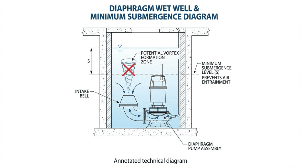
- Submergence Definition: Engineers must distinguish between NPSH required submergence (to prevent vapor formation) and Vortex Suppression submergence (to prevent air core formation). The latter is almost always the controlling factor in Diaphragm Wet Well Design and Minimum Submergence to Prevent Vortexing.
Installation Environment & Constructability
Diaphragm walls are often selected for deep applications (50ft+), making post-construction modifications nearly impossible.
- Tolerances: Hydraulic stability relies on precise geometry. A floor splitter that is misaligned by inches can induce swirl rather than prevent it. Specifications must call for tight construction tolerances on concrete fillets and benching.
- Access for Cleaning: Deep wells accumulate grit. The design must accommodate cleaning heads or mixing nozzles. However, incorrectly placed mixers can be a source of rotation. Mixer placement must be modeled alongside pump operation.
Reliability, Redundancy & Failure Modes
Understanding failure modes helps in drafting robust specifications.
- Air Entrainment: Even 1-2% entrained air by volume can reduce pump efficiency by 10-15%. Higher percentages lead to de-priming and surging.
- Sub-surface Vortices: While surface vortices are visible, sub-surface vortices originate from the floor or walls and enter the bell. These are invisible from the surface but cause impulsive loading on the impeller, significantly reducing Mean Time Between Failures (MTBF) of bearings and seals.
Lifecycle Cost Drivers
The trade-off in Diaphragm Wet Well Design and Minimum Submergence to Prevent Vortexing is often between excavation depth (CAPEX) and operational reliability (OPEX).
- Excavation Cost: Every vertical foot of a diaphragm wall is expensive. Engineers face pressure to raise the floor. However, insufficient depth reduces submergence, leading to vortexing.
- Energy penalty: Vortex-induced pre-rotation reduces hydraulic efficiency. Over a 20-year lifecycle, a 5% efficiency loss due to poor intake conditions can exceed the cost of the initial concrete work.
Comparison of Intake Geometries and Analysis Methods
The following tables provide a structured comparison of different wet well geometries relevant to diaphragm wall construction, as well as the validation methods used to ensure Diaphragm Wet Well Design and Minimum Submergence to Prevent Vortexing is adequate.
Table 1: Wet Well Geometry Comparison for Deep Excavations
| Geometry Type | Features | Best-Fit Applications | Limitations/Risk of Vortexing | Typical Maintenance |
|---|---|---|---|---|
| Confined Circular (Open Sump) | Simple cylinder, uniform floor, pumps hanging freely or on pedestals. | Small, low-flow stations; Stormwater where grit suspension is not primary. | High Risk: Circular walls promote bulk rotation. Requires deep submergence to suppress vortices. Poor hydraulics for large pumps. | High grit accumulation in dead zones. Requires periodic manual cleaning. |
| Circular with Formed Suction Intake (FSI) | Uses a manufactured “shoe” or draft tube attached to the pump inlet to guide flow. | Restricted space applications; Retrofits where submergence is limited. | Low Risk: The FSI conditions flow right at the inlet. Reduces required submergence significantly. | Minimal. The high velocity in the FSI prevents clogging, though the FSI itself adds cost. |
| Trench-Type (Self-Cleaning) | An internal rectangular trench constructed within the circular diaphragm shell. | High-solids wastewater; Variable flow conditions (VFDs). | Low/Medium Risk: Excellent for solids transport. Confining walls suppress rotation, but transitions must be smooth. | Self-cleaning design minimizes maintenance labor. |
| Circular with Baffles & Fillets | Standard circular sump modified with floor splitters, anti-rotation baffles, and 45° fillets. | Medium to Large Wastewater Lift Stations (Standard Municipal Spec). | Medium Risk: Effective if designed per HI 9.8. Baffle integrity is critical. | Baffles can catch rags (“ragging”). Harder to clean behind baffles. |
Table 2: Design Validation Matrix
| Validation Method | Applicability | Key Constraints | Relative Cost | Impact on Project Timeline |
|---|---|---|---|---|
| Standard Formula (ANSI/HI 9.8) | Standard geometries (Rectangular, Formed Suction). Low flow (< 5,000 GPM). | Cannot predict performance for non-standard, crowded, or circular geometries accurately. | Low (Engineering Hours) | Negligible |
| Computational Fluid Dynamics (CFD) | Complex geometries, retrofits, circular wells, trench intakes. | Requires accurate boundary conditions. Single-phase CFD may miss air-core formation (requires multiphase). | Medium ($15k – $50k) | 4-8 Weeks |
| Physical Hydraulic Modeling (Scale Model) | Critical infrastructure (> 40,000 GPM), high consequence of failure, unique diaphragm shapes. | Expensive and requires physical lab space. The “Gold Standard” for submergence verification. | High ($75k – $200k+) | 12-20 Weeks |
Engineer & Operator Field Notes
Design is theory; operation is reality. The following insights bridge the gap between the drafting table and the pump station floor, focusing on practical aspects of Diaphragm Wet Well Design and Minimum Submergence to Prevent Vortexing.
Commissioning & Acceptance Testing
Verifying hydraulic performance during commissioning is difficult because you cannot always “see” the problem. Surface vortices are visible, but pre-rotation and sub-surface vortices are not.
- Free Surface Observation: During the Site Acceptance Test (SAT), bring the wet well down to the minimum design level with maximum pumps running. Use high-powered lighting to observe the water surface around the pump columns. Any organized dimpling or swirl that pulls floating debris downward is a failure criterion.
- Vibration Baselining: Record vibration spectra at various wet well levels. If vibration spikes at specific low levels (but is normal at high levels), this is a strong indicator of intake instability or vortexing.
- Air Release Monitoring: Watch the air release valves on the discharge force main. Excessive, rhythmic venting suggests the pumps are ingesting air, indicating that the minimum submergence setpoint is too aggressive.
Common Specification Mistakes
A frequent error in municipal specifications is cutting and pasting requirements from rectangular wet well standards into diaphragm wall projects.
- Missing Anti-Rotation Features: Specifying a flat floor in a circular wet well is a recipe for disaster. The Coriolis effect and residual circulation will create bulk rotation. Specifications must include a central floor splitter or baffle wall to break the rotation.
- Over-reliance on “D”: While submergence is often calculated as a function of the bell diameter ($D$), this rule assumes a standard approach velocity. In compact diaphragm wells, approach velocities may be higher, requiring greater submergence ($S$) than the standard $S = D + 2.3F_D$ formula suggests.
O&M Burden & Strategy
The operational strategy significantly impacts the risk of vortexing.
- Cleaning Cycles: In diaphragm wells, grit tends to accumulate in the “shadows” of the pumps. As grit piles up, it changes the effective floor geometry, potentially creating ramps that induce swirl. Regular cleaning is not just for capacity; it is for hydraulic stability.
- Level Control Hysteresis: Operators often lower the “Pump Off” setpoint to increase effective storage volume and reduce cycle count. However, lowering this setpoint by even 6 inches can violate the critical submergence requirement, leading to vortexing at the end of every pump cycle. This repetitive air ingestion destroys mechanical seals.
Troubleshooting Guide
If a pump in a diaphragm well is vibrating or experiencing flow fluctuation:
- Check Level: Does the vibration correlate with wet well level? If it worsens as the level drops, it is likely submergence-related.
- Check Rotation: Drop a float (like a weighted tennis ball) into the well. Does it orbit the pump column? Rapid orbiting indicates bulk rotation, requiring baffle retrofits.
- Check Pre-rotation: Inspect the pump bell and impeller eye during a teardown. localized erosion on one side of the bell lip or the leading edge of the impeller vanes often indicates pre-rotation.
Design Details and Sizing Methodologies
Calculating Diaphragm Wet Well Design and Minimum Submergence to Prevent Vortexing requires adherence to physics-based formulas, primarily derived from ANSI/HI 9.8. However, engineers must apply safety factors for deviations from ideal geometry.
Sizing Logic & Methodology
The defining parameter for minimum submergence ($S$) is the Froude number ($F_D$) at the bell intake. The Hydraulic Institute provides the baseline formula:
S = D * (1 + 2.3 * F_D)
Where:
- S: Minimum submergence (distance from fluid surface to the inlet bell lip).
- D: Outside diameter of the suction bell.
- F_D: Froude number = $V / sqrt{g * D}$
- V: Velocity at the suction inlet face.
- g: Gravitational acceleration.
Step-by-Step Approach:
- Calculate Inlet Velocity (V): Determine flow per pump and bell diameter. HI recommended velocity at the inlet face is typically 2.0 to 5.5 ft/s.
- Calculate Froude Number: A higher Froude number implies higher inertial forces relative to gravitational forces, requiring deeper submergence.
- Calculate Baseline S: Use the formula above.
- Apply Geometry Factor: For Diaphragm/Circular wells without formed suction intakes, add a safety margin (typically 1.2x to 1.5x the calculated S) because the formula assumes a straight, rectangular approach channel which does not exist in a circular shaft.
Specification Checklist
When reviewing a design for a diaphragm wet well, ensure the following are present:
- Floor Geometry: Is there a central flow splitter or “camelback” ramp to prevent floor-attached vortices?
- Wall Clearances: Is the distance from the back wall to the pump centerline ($B$) minimized? In circular wells, this is tricky. A large gap allows fluid to circulate behind the pump, causing swirl. HI 9.8 recommends $B = 0.75D$.
- Fillets: Are there 45-degree fillets at the wall-to-floor interface to eliminate stagnation zones?
- Submergence Alarm: Is the Low Level Alarm set above the calculated minimum submergence $S$?
Standards & Compliance
The governing standard is ANSI/HI 9.8 (Rotodynamic Pumps for Pump Intake Design).
Note on Diaphragm Walls: HI 9.8 provides specific guidance for “Circular Pump Stations” (Section 9.8.3.2). It explicitly states that circular sumps are sensitive to swirl and generally require baffling. Deviating from the standard geometries in HI 9.8 without conducting a physical model study or validated CFD analysis is considered a professional risk and often voids performance guarantees from pump manufacturers.
Frequently Asked Questions
What is the difference between NPSH Required and Minimum Submergence?
This is a critical distinction. NPSH Required (NPSHr) is the pressure energy required by the pump to prevent liquid from vaporizing (cavitation) inside the impeller eye. Minimum Submergence is the physical depth of liquid required above the intake to prevent the formation of air-entraining vortices on the surface. You can satisfy NPSHr but still fail due to vortexing if the submergence is insufficient. In Diaphragm Wet Well Design and Minimum Submergence to Prevent Vortexing, submergence is usually the controlling parameter.
Why are circular diaphragm wells more prone to vortexing than rectangular sumps?
Rectangular sumps guide flow linearly toward the pump, naturally suppressing rotation. Circular diaphragm wells are geometrically symmetrical, which allows fluid to rotate (swirl) around the vertical axis of the well, especially if flow enters tangentially or if pumps operate asymmetrically. This bulk rotation creates a “tornado” effect, organizing into strong surface vortices that are difficult to break without intrusive baffles.
When is a physical model study required for a diaphragm wet well?
Per ANSI/HI 9.8, a physical model study is recommended when the flow per pump exceeds 40,000 GPM (2,500 L/s) or when the geometry deviates significantly from standard designs. For diaphragm wells, if the design does not use a Formed Suction Intake (FSI) or strictly follow the “confined circular” guidelines with baffles, a model study (or high-fidelity CFD) is strongly advised to validate Diaphragm Wet Well Design and Minimum Submergence to Prevent Vortexing.
Can CFD replace physical modeling for wet well design?
Increasingly, yes. However, it must be multiphase CFD (Volume of Fluid – VOF) to accurately predict free-surface vortices (air cores). Single-phase CFD is excellent for predicting sub-surface swirl and velocity distribution but cannot directly visualize air entrainment. For critical infrastructure, many engineers use CFD for design optimization and a physical model for final validation.
How do formed suction intakes (FSI) assist in diaphragm well design?
An FSI (often called a “shoe”) is a shaped inlet attached to the pump bell that conditions the flow, effectively creating a “mini-rectangular sump” environment at the impeller eye. By controlling the acceleration of fluid into the pump, FSIs significantly reduce the required minimum submergence and make the pump less sensitive to the bulk rotation typical in circular diaphragm wells. They are highly recommended for space-constrained designs.
What is the typical minimum submergence ratio for centrifugal pumps?
While calculation is necessary, a typical rule of thumb for preliminary layout is that Minimum Submergence ($S$) is often 1.5 to 2.0 times the Bell Diameter ($D$). However, high-flow or high-head pumps may require significantly more. Never rely on rules of thumb for final construction drawings; use the HI 9.8 calculation method.
Conclusion
Key Takeaways
- Geometry Matters: Circular diaphragm wells naturally promote rotation. You cannot rely on “standard” sump design logic.
- Separate Your Metrics: Minimum Submergence prevents vortices; NPSH prevents vapor cavitation. Satisfy both independently.
- Respect the Froude Number: Submergence is a function of inlet velocity. Higher velocity requires deeper submergence.
- Spec Baffles: Floor splitters and anti-rotation baffles are not optional in circular wet wells; they are essential for pump survival.
- Model It: For flows >5,000 GPM or complex layouts, invest in CFD or physical modeling. The cost of analysis is a fraction of the cost of a retrofit.
The successful implementation of Diaphragm Wet Well Design and Minimum Submergence to Prevent Vortexing lies at the intersection of civil structural constraints and hydraulic fluid dynamics. As municipalities push for deeper lift stations to manage storage and gravity flow, the diaphragm wall becomes a ubiquitous solution. However, the engineering team must remain vigilant.
Simply creating a hole in the ground and suspending pumps within it is a recipe for hydraulic failure. By strictly adhering to ANSI/HI 9.8 standards, understanding the unique flow patterns of circular shafts, and validating designs through calculation and modeling, engineers can ensure these critical assets perform reliably. The cost of proper design validation is minimal compared to the lifecycle cost of bearing replacements, seal failures, and the operational headaches caused by chronic air entrainment.
For the decision-maker, the path forward is clear: prioritize hydraulic stability in the specification phase, demand rigorous verification of submergence calculations, and recognize that in the world of fluid mechanics, geometry dictates performance.