
A Comprehensive Guide to Wastewater Treatment Pumps
Wastewater Treatment Pumps: Scope and Role in the Treatment Train
Wastewater treatment is a crucial process in ensuring clean and safe water for our communities and the environment. It involves the removal of contaminants and pollutants from wastewater to make it suitable for discharge or reuse. One of the key components in this process is wastewater treatment pumps, which play a vital role in moving and treating wastewater. In this article, we’ll explore the types of wastewater treatment pumps, their functionality, various use cases, and key manufacturers and products.
Pumping is the single largest consumer of electricity at most treatment facilities, commonly accounting for 30 to 50 percent of a plant’s total energy use, and pump failures are among the most frequent causes of unplanned overflows and permit excursions. Selection therefore carries both an operating cost consequence and a compliance consequence. Within the broader family of pumps used in wastewater treatment, the equipment covered here spans raw sewage lift duty, intermediate process transfer, sludge and biosolids handling, chemical metering, and the ancillary plant-water services that keep a facility running.
What separates wastewater pumping from clean-water pumping is the fluid itself. Influent carries rags, grit, fibrous material, grease, and dissolved gases, and its composition changes hour by hour. A pump specified purely on flow and head will meet its duty point on a test stand and then rag up, cavitate, or wear out prematurely in service. Solids handling capability, materials of construction, and the ability to run stably away from best efficiency point matter as much as the hydraulic rating.
The sections that follow cover the major pump types and their use cases, then work through the full range of subcategories in this equipment class, the selection framework that connects them, comparison data, field practice, and the standards that govern specification.
Types of Wastewater Treatment Pumps
Wastewater treatment pumps are designed to handle a wide range of fluids and solids. They can be categorized into several types, each tailored for specific functions within the treatment process:
Submersible Pumps
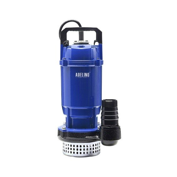
Submersible pumps, like those offered by Xylem, are designed to operate underwater. These pumps are commonly used for wastewater removal in sewage systems, stormwater drainage, and wastewater treatment plants. Their submersible nature allows them to efficiently handle solids and transport wastewater over long distances.
Centrifugal Pumps
Centrifugal pumps are versatile and widely used in various stages of wastewater treatment. They work by using a rotating impeller to create a flow of fluid. Centrifugal pumps are efficient in handling low to medium viscosity liquids and are employed in lift stations, aeration tanks, and sludge handling.
Positive Displacement Pumps
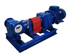
Positive displacement pumps, such as diaphragm and progressive cavity pumps, are suitable for handling viscous and abrasive fluids. They are essential in dosing and metering applications, chemical feed systems, and handling sludges with a high solids content.
Grinder Pumps
Grinder pumps are designed to macerate and grind solid waste into smaller particles before pumping, making them ideal for residential and commercial sewage systems. These pumps help prevent clogs and blockages in the wastewater infrastructure.
Air Diaphragm Pumps
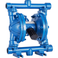
Air diaphragm pumps are air-operated double-diaphragm pumps used for the transfer and removal of abrasive or corrosive wastewater. They find applications in chemical processing, filter press feed, and handling contaminated water.
Peristaltic Pumps
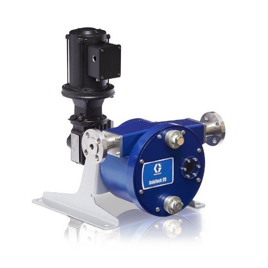
Rollers or shoes in a peristaltic pump compress the tube or hose as they rotate, creating a vacuum which draws fluid through the tube. This gentle and pulsation-free action makes them suitable for shear-sensitive fluids. Peristaltic pumps are commonly found in laboratories and small-scale wastewater treatment applications, especially when accurate dosing is required.
Functionality and Use Cases
The functionality and use cases of wastewater treatment pumps are as diverse as the types themselves:
Primary Treatment: Submersible pumps and centrifugal pumps play a significant role in lifting and transporting raw wastewater from collection points to treatment facilities.
Secondary Treatment: Centrifugal pumps are commonly used for aeration, mixing, and recirculation processes in biological treatment systems.
Tertiary Treatment: Positive displacement pumps and air diaphragm pumps are utilized in the dosing and handling of chemicals for disinfection, phosphorus removal, and other advanced treatment processes.
Solids Handling: Grinder pumps are indispensable for breaking down and transporting solid waste in residential and commercial wastewater systems.
High-Pressure Applications: Certain treatment processes require high-pressure pumps, which can be found in various types, including multistage centrifugal pumps.
Key Manufacturers and Products
Xylem, as mentioned earlier, is a reputable manufacturer of wastewater treatment pumps. Their product range includes submersible pumps, centrifugal pumps, and many other types designed to meet the diverse needs of the industry. Other notable manufacturers in the field include Grundfos, KSB, and ITT Goulds Pumps.
Grundfos: Grundfos offers a range of wastewater pumps, including submersible sewage pumps, sludge and solids handling pumps, and chemical dosing pumps.
KSB: KSB manufactures a wide variety of wastewater pumps, such as non-clogging centrifugal pumps, submersible mixers, and aeration systems.
ITT Goulds Pumps: ITT Goulds Pumps provides robust wastewater pumps for demanding applications, including single-stage and multi-stage centrifugal pumps.
Innovations in Wastewater Treatment Pumps
In recent years, the wastewater treatment industry has seen significant innovations aimed at improving pump efficiency, durability, and environmental sustainability. These innovations include:
Variable Frequency Drives (VFDs): VFDs allow pumps to adjust their speed based on demand, resulting in energy savings and longer pump life.
Smart Pumping Systems: These systems use data and automation to optimize pump operation, reduce energy consumption, and predict maintenance needs.
Improved Materials and Coatings: Advancements in materials and coatings have extended the lifespan of pumps, particularly in corrosive and abrasive environments.
Energy-Efficient Designs: Manufacturers are focusing on designing pumps with improved energy efficiency to reduce operational costs and environmental impact.
Subcategory Overview: The Wastewater Pumping Equipment Class
The pump types described above are the hydraulic families. In practice, specifying and maintaining pumping at a treatment facility also involves the structures that house them, the services that keep them running, the instrumentation that watches them, and the ancillary plant-water equipment that supports the process. The subsections below cover each area in the equipment class, what it addresses, and where it fits.
Pump Station Design
Pump Station Design covers the engineering of the structure and system around the pumps: wet well geometry, sump volume and cycle time, submergence and intake approach conditions, valve and header arrangement, electrical service, and standby power. Wet well sizing balances two competing constraints, since too small a volume causes excessive motor starts and too large a volume allows septicity and grease accumulation. Intake design is where most chronic station problems originate, because vortexing, pre-swirl, and uneven approach flow degrade pump performance in ways that no amount of pump replacement will fix. Station design also determines whether the facility can be maintained safely, since access, hoisting provisions, and the ability to isolate one pump while the others run are decided at the drawing stage.
Pumping Stations in Wastewater
Pumping Stations in Wastewater addresses the role these facilities play within the collection system as a whole. Lift stations move flow over topographic high points and into interceptors where gravity alone cannot carry it, and a single station failure can surcharge the sewers behind it within hours. Submersible stations dominate new construction on cost and footprint grounds, while dry-pit configurations remain preferred where operators need access to the pumps without confined space entry. Reliability provisions are the defining design question: firm capacity with the largest unit out of service, standby generation or a connection point for a portable unit, and telemetry that alarms on high level before an overflow occurs.
Pumping Stations
The broader treatment of Pumping Stations extends beyond wastewater collection to water distribution, stormwater, and industrial applications, where the same structural and hydraulic principles apply to cleaner fluids and different reliability requirements. Booster and distribution stations are sized around system pressure zones and fire flow rather than peak sanitary flow. Stormwater stations operate intermittently at very high capacity and spend most of their life idle, which changes both the equipment selection and the maintenance regime. Understanding the differences prevents the common error of applying clean-water station design conventions to sewage service.
Chemical Pumps
Chemical Pumps handle the metering and transfer of treatment chemicals, most commonly sodium hypochlorite, but also ferric chloride, caustic, polymer, and acids. These duties demand accuracy over throughput, and diaphragm metering, peristaltic, and progressive cavity designs dominate as a result. Material compatibility is the governing selection criterion, since a pump head, seal, or tubing material that is wrong for the chemical will fail in weeks rather than years. Hypochlorite service adds a specific complication in the form of off-gassing, which vapor-locks conventional diaphragm heads and is the reason degassing valve heads and flooded suction arrangements are standard practice.
Wastewater Treatment Pumps Overview
A general wastewater treatment pumps overview is a useful orientation for operators and engineers new to the equipment class, mapping pump families to the treatment stages they serve. Raw sewage lift, primary sludge withdrawal, return and waste activated sludge, scum, filtrate and centrate return, and chemical feed each have distinct fluid characteristics and each favors a different pump family. Working through the plant stage by stage is the most reliable way to build a complete pump inventory and identify which units are single points of failure.
Wastewater Treatment Plant Pumps
Coverage of wastewater treatment plant pumps focuses on the in-plant duties specifically, as distinct from collection system lift stations. In-plant pumping tends to involve shorter static heads, more frequent starts, and more difficult fluids, particularly on the sludge side where solids concentrations of 2 to 6 percent are routine and thickened streams can exceed 8 percent. Because in-plant pumps are usually accessible and non-redundant, their maintenance strategy differs from the run-to-failure approach that is sometimes acceptable for a duplicated lift station.
Sludge Pumps
Equipment for sludge pumps in wastewater treatment handles the most demanding fluid at the facility. Sludge is non-Newtonian, abrasive, and highly variable, and its apparent viscosity rises sharply with solids concentration, so friction losses calculated on water properties will badly understate the required head. Progressive cavity, rotary lobe, plunger, and recessed impeller pumps each occupy a niche here depending on solids content, abrasiveness, and whether the duty is continuous or intermittent. Suction piping is critical, since sludge pumps are far more sensitive to suction restriction than clean water pumps and starved suction is the most common cause of poor performance.
Electric Wastewater Pump
The Electric Wastewater Pump category covers the motor and drive side of the equipment: enclosure ratings, insulation class, service factor, thermal protection, moisture sensing, and the differences between submersible motors and dry-mounted units. Submersible motors depend on the pumped fluid for cooling, which means running one in a dewatered wet well or with the impeller de-rated causes rapid overheating. Motor selection also interacts with the drive, since operation on a variable frequency drive introduces harmonics, bearing currents, and reduced cooling at low speed that a constant-speed application never encounters.
Non-Clog and Solids Handling Selection
Solids handling capability is what distinguishes a wastewater pump from a water pump, and specifying it properly requires attention to sphere passage, impeller vane count, and the leading edge geometry that determines whether rags shed or accumulate. Two-vane and single-vane impellers pass solids well but are less efficient and generate more radial load than the multi-vane designs used in clean water. Vortex and recessed impeller pumps handle the worst fluids with the lowest clogging risk but sacrifice significant efficiency to do it. Chopper and grinder designs cut solids at the inlet instead of passing them, which solves ragging at the cost of wear parts and power draw. Engineers writing a lift station specification will find the detailed criteria in our guide to non-clog pumps for municipal service.
Vertical Pumps
Vertical Pumps include vertical turbine, vertical column, and vertical inline configurations, all of which place the driver above the liquid and the hydraulic end below it. This arrangement suits deep wet wells, intake structures, and applications where flooding of the motor must be avoided without resorting to a submersible design. Column and lineshaft length introduces alignment, bearing lubrication, and critical speed considerations that horizontal pumps do not have. Vertical configurations also concentrate the maintenance burden on removal, since servicing the bowl assembly usually requires pulling the entire column with a crane.
Sealed Pumps
Sealed Pumps covers shaft sealing technology, which is the most common single point of failure in wastewater pumping. Packing is inexpensive and forgiving but requires continuous leakage, regular adjustment, and clean seal water. Single and double mechanical seals eliminate routine leakage and operator attention but fail abruptly rather than gradually, and in abrasive service they demand a properly designed flush plan. Sealless designs, including magnetic drive and canned motor pumps, remove the seal entirely and are used where leakage is unacceptable, though they are generally unsuited to solids-bearing fluids.
Drainage Pumps
Drainage Pumps handle building and site dewatering duties inside a treatment facility: gallery sumps, basement drains, tank drain-down, and stormwater collection around process structures. These units are typically small submersibles that run infrequently and are the first thing forgotten in a maintenance program, which is why a flooded gallery is a common consequence of an otherwise routine storm. Automatic level control, a check valve that actually seats, and periodic exercise are the three provisions that keep them functional.
Cooling Pumps
Cooling Pumps circulate water through heat exchangers serving blowers, engine generators, digester heating loops, and process equipment. These are clean-water duties inside a wastewater facility, and they are frequently specified with less rigor than process pumps despite the fact that their failure shuts down the equipment they serve. Fouling and scaling in the loop, rather than the pump itself, cause most cooling system problems, so water treatment of the loop and provision for cleaning are as important as the pump selection.
Condensate Pumps
Condensate Pumps return condensate from steam and heating systems, which at treatment plants most often means digester heating loops and building HVAC. Condensate is hot, low in dissolved solids, and frequently slightly acidic from dissolved carbon dioxide, which corrodes cast iron and carbon steel components. Net positive suction head is the governing design constraint because the fluid sits close to its saturation temperature, so receiver elevation and suction line design determine whether the pump cavitates.
Water Pumps
Water Pumps as a general category cover the clean-water duties present at every treatment facility: plant potable and non-potable water systems, seal water supply, chemical dilution water, and washdown. These systems are hydraulically simple but operationally critical, since seal water failure will destroy mechanical seals across the plant within hours. Cross-connection control between potable and plant water systems is a regulatory requirement and a recurring inspection finding.
Water Jet Pump
The Water Jet Pump is an ejector-type device with no moving parts, using a high-velocity motive stream to entrain and move a secondary fluid. In water and wastewater work these appear as eductors for chemical mixing and induction, as priming devices for larger pumps, and in small-scale dewatering. Efficiency is low compared with a rotodynamic pump, so their justification is reliability and simplicity in duties where a conventional pump would clog or where no power is available at the point of use.
In-Line Fuel Pump
The In-Line Fuel Pump supports the standby power systems that treatment plants depend on during utility outages. Diesel fuel transfer and day-tank fill duties are small in capacity but consequential, since a generator that cannot be fueled during an extended outage leaves the plant without pumping. Fuel polishing and periodic quality testing matter as much as the pump itself, because stored diesel degrades and microbial growth in tanks is a common cause of generator failure at the worst moment.
Cavitation
Cavitation occurs when local pressure at the impeller eye falls below the vapor pressure of the fluid, forming bubbles that collapse violently as pressure recovers. The damage is unmistakable in service: pitted impeller vanes, a characteristic gravel-in-the-pump sound, unstable discharge pressure, and accelerated bearing and seal wear. Prevention comes down to keeping net positive suction head available comfortably above the pump’s required value across the full operating range, typically with a margin of several feet rather than a marginal pass. Suction piping restrictions, excessive lift, high fluid temperature, and operation far to the right of best efficiency point are the usual contributors.
Vibration Monitoring System for Pumps
A Vibration Monitoring System for Pumps converts pump maintenance from calendar-based to condition-based. Spectral analysis distinguishes between imbalance, misalignment, bearing defects, looseness, and cavitation, each of which produces a characteristic frequency signature, and it does so weeks or months before failure. Permanently installed sensors are justified on large or critical units, while portable route-based collection covers the rest of the plant economically. The value depends entirely on establishing baseline signatures when equipment is known to be healthy, since the diagnostic method is comparative.
Pump, Valve, and Gearbox Repair Services
Pump, valve, and gearbox repair in water and wastewater services covers the installation and repair capability that utilities either build in-house or contract out. The decision hinges on fleet size, staff skill, and how quickly a failed unit must return to service. Utilities with standardized equipment and a stocked spares program can rebuild in-house economically, while those with a diverse installed base usually find contracted repair more practical.
Pump, Valve, and Gearbox Repair
The technical side of Pump, Valve, and Gearbox Repair addresses what actually happens during a rebuild: wear ring and clearance restoration, impeller trimming and balancing, shaft runout checks, bearing and seal replacement, and post-repair performance verification. Restoring running clearances is where most of the recovered efficiency comes from, and a rebuild that skips it returns the pump to service still consuming excess energy. Gearbox work on mechanically driven equipment follows a parallel logic of bearing condition, backlash, and lubricant analysis.
Retrofit vs Replace
The General Pump Retrofit vs Replace decision recurs constantly in aging stations. Repeated rebuilds on a pump that no longer matches its duty point waste money on equipment that will remain inefficient, while wholesale replacement of a functional unit wastes capital. The practical test combines cumulative repair cost against replacement cost, measured efficiency against current best available technology, parts availability, and whether the original duty point still reflects actual system conditions after decades of collection system change.
Top Wastewater Pump Manufacturers
The Top Wastewater Pump Manufacturers area compares the major OEMs across product breadth, hydraulic performance, solids handling design, service network, and parts availability. Xylem, Grundfos, KSB, Sulzer, ITT Goulds, Vaughan, Gorman-Rupp, and Ebara cover most municipal installations, each with a recognized strength. Standardizing a fleet on one or two brands reduces spares inventory and shortens operator and mechanic training, and that consideration frequently outweighs a modest per-unit price advantage on any single procurement.
Gould Pumps: Introduction
A Beginner’s Guide to Understanding Gould Pumps introduces one of the most widely installed lines in North American water and wastewater service, covering the model families and the duties each is built for. The installed base is large enough that most utilities encounter these units regardless of their procurement preferences, which makes familiarity with the model numbering and configuration options practically useful.
Gould Pumps: Selection and Maintenance
Gould Pumps Selection and Maintenance moves from orientation to practice, covering duty point selection, material options for corrosive and abrasive service, seal configuration, and the maintenance intervals that apply to the common model families. The maintenance content is where the value sits for utilities with an existing installed base, since correct rebuild practice and parts identification determine whether a repair restores original performance.
Impeller Equipment Comparison
Head-to-head equipment evaluations such as the krohne vs hach impeller equipment comparison examine how competing suppliers differ on measurement accuracy, installation requirements, and best-fit applications for impeller-related instrumentation and equipment. Comparisons of this kind are most useful when read against a defined application rather than in the abstract, since the ranking changes with pipe size, fluid, and accuracy requirement.
OEM Comparisons and Applications
Broader OEM Comparisons Applications content evaluates suppliers against each other across a range of duties, which helps a specifying engineer narrow a shortlist before requesting quotations. The recurring lesson from these comparisons is that supplier differentiation in mature product categories comes less from headline performance than from service coverage, lead time, and parts logistics.
Selection and Specification Framework
Step One: Define the Fluid, Not Just the Flow
Every wastewater pump specification should begin with a fluid description: solids concentration and character, rag and grit content, temperature, pH, chemical constituents, and abrasiveness. This determines the pump family before any hydraulic calculation happens. Raw sewage demands solids passage; thickened sludge demands positive displacement; chemical feed demands material compatibility and metering accuracy. Specifying a hydraulic duty point without characterizing the fluid is the most common root cause of a pump that meets its curve and still fails in service.
Step Two: Establish the True System Curve
Calculate static head from actual wet well levels and discharge elevations, then add friction losses using fluid properties rather than water properties where the fluid is sludge. Model the system across the full range of operating conditions, not one design point, because a force main’s friction loss varies with age and grease accumulation and a wet well’s static head varies through every pump cycle. Plot the pump curve against the system curve and confirm that the intersection sits within the acceptable operating region, typically between 70 and 120 percent of best efficiency point for continuous duty.
Step Three: Verify NPSH Margin
Compare net positive suction head available against required across the entire operating range, not only at the duty point. Required NPSH rises sharply at high flow, so a pump that is comfortable at design conditions may cavitate when a second unit shuts down and the remaining pump runs out on its curve. A margin of at least several feet is normal practice, with more where the fluid is hot, contains dissolved gas, or the suction line is long.
Step Four: Select the Drive and Control Strategy
Constant speed with on-off level control is simplest and remains appropriate for many lift stations. Variable frequency drives reduce energy consumption on duties with genuine flow variation and soften the hydraulic transients associated with starts and stops, but they introduce minimum speed limits below which solids settle in the force main and the pump loses its self-scouring velocity. Maintaining a scouring velocity of roughly 2 ft/s in the force main is the practical floor on speed reduction, regardless of what the energy calculation suggests.
Step Five: Design for Maintenance from Day One
Decide how each pump will be removed, where it will be set down, and what has to be isolated before work begins. Provide isolation valves that actually seat, a hoisting arrangement rated for the heaviest component, and enough redundancy that maintenance can proceed without taking the station out of service. Equipment that cannot be maintained safely will not be maintained, and the resulting run-to-failure pattern costs far more than the provisions would have.
Step Six: Evaluate Lifecycle Cost
Energy typically accounts for 60 to 80 percent of the total ownership cost of a pumping installation over a 20-year life, with purchase price often below 10 percent. A few points of efficiency, or a control strategy that keeps the pump near best efficiency point instead of throttling, will outweigh a substantial first-cost difference. Build the comparison on measured or realistically modeled operating hours rather than nameplate assumptions.
Comparison Tables
| Type | Key Features | Best-Fit Applications | Limitations | Relative Cost | Maintenance Profile |
|---|---|---|---|---|---|
| Submersible | Motor and hydraulic end submerged; compact station footprint; guide rail removal | Lift stations, wet wells, stormwater, drainage sumps | Motor cooling depends on submergence; confined space or hoist needed for service | Low–Moderate | Seal and cable inspection; oil chamber checks; guide rail servicing |
| Centrifugal (dry pit) | Accessible driver; broad hydraulic range; easy monitoring | Raw sewage lift, in-plant transfer, recirculation | Requires dry well structure and drainage; more building volume | Moderate | Packing or seal service; alignment and bearing monitoring |
| Positive displacement | Flow largely independent of discharge pressure; handles high viscosity | Sludge transfer, polymer, thickened biosolids, metering | Requires relief protection; wear parts on abrasive service | Moderate–High | Stator, rotor, or lobe replacement on a defined interval |
| Chopper / grinder | Cuts solids at the inlet rather than passing them | Rag-heavy raw sewage, scum, septage receiving | Cutter wear parts; higher power draw | Moderate–High | Cutter inspection and periodic replacement |
| Air-operated diaphragm | Self-priming, dry-run tolerant, no electrical connection | Filter press feed, sump and spill transfer, corrosive duty | Low efficiency; high compressed air consumption | Low | Diaphragm and check ball replacement |
| Peristaltic | Only the hose contacts fluid; accurate and gentle; no seals | Chemical metering, polymer, lime slurry, sampling | Limited capacity and pressure; hose is a consumable | Moderate | Scheduled hose replacement; lubricant checks |
| Plant Duty | Typical Fluid Condition | Common Selection | Primary Failure Risk |
|---|---|---|---|
| Raw sewage lift | Rags, grit, variable flow | Submersible or dry-pit non-clog; chopper where ragging is severe | Clogging and seal failure |
| Primary sludge | 2–6% solids, abrasive, gritty | Progressive cavity, plunger, or recessed impeller | Abrasive wear; starved suction |
| Return activated sludge | 0.5–1% solids, continuous duty | Axial or mixed flow, low head high volume | Operating away from best efficiency point |
| Thickened biosolids | 4–8%+ solids, non-Newtonian | Progressive cavity or rotary lobe | Underestimated friction loss; dry running |
| Chemical feed | Corrosive, gas-forming, low flow | Diaphragm metering or peristaltic | Vapor lock; material incompatibility |
| Plant and seal water | Clean, continuous | End suction or multistage centrifugal | Loss of supply damaging seals plant-wide |
Field Notes
Commissioning Considerations
Witness a performance test at the actual installed condition, not just a factory certificate. Record amperage, discharge pressure, suction condition, and flow at several points across the operating range, and log the resulting operating point against the published curve. Verify that the level control setpoints produce an acceptable number of starts per hour for the motor size, and confirm that alternation between duty and standby units actually works. Take baseline vibration signatures on every unit before the station goes into service, since the diagnostic value of monitoring depends entirely on having a healthy reference.
Common Specification Mistakes
- Sizing on a duty point that includes a large safety margin. An oversized pump runs to the left of best efficiency point, recirculates internally, and wears rapidly while consuming more energy than a correctly sized unit.
- Calculating sludge friction losses with water properties. Apparent viscosity rises sharply with solids concentration and the resulting head requirement can be several times the water-based calculation.
- Ignoring wet well geometry and intake approach conditions. Vortexing and pre-swirl degrade performance in ways no pump replacement will correct.
- Setting a VFD minimum speed below force main scouring velocity. Solids deposit in the force main and eventually reduce its capacity permanently.
- Specifying mechanical seals without a flush plan in abrasive service. Seal faces are destroyed by grit within weeks in the absence of a properly designed flush.
- Omitting a means of removal. Every submerged component needs a defined lift path and rated hoisting provision.
- Assuming the original duty point still applies. Collection system growth, I&I reduction, and force main condition all shift the system curve over decades.
Operations and Maintenance Comparison
Submersible pumps concentrate maintenance on seals, cable entries, and oil chamber integrity, and moisture detection is the early warning that distinguishes a seal replacement from a motor rewind. Dry-pit centrifugals shift attention to alignment, bearings, and packing or seal service, all of which can be performed without confined space entry. Progressive cavity pumps have a defined stator wear interval that should be budgeted rather than deferred, and they are unforgiving of dry running for even a short period. Chopper and grinder units require cutter inspection on a schedule tied to influent characteristics rather than run hours. Across every family, the most valuable single practice is trending motor amperage and discharge pressure, because a change in either is a leading indicator of clogging, wear, or a shifting system curve.
Troubleshooting by Symptom
Reduced flow with normal amperage typically indicates a clogged impeller or a closed or partially seated valve. Reduced flow with elevated amperage suggests binding, bearing failure, or an obstruction in the volute. Noise resembling gravel with erratic discharge pressure is cavitation, and the investigation should start with suction conditions rather than the pump. Frequent motor starts point to insufficient wet well volume or level control setpoints spaced too closely. Repeated seal failures on a single unit usually trace to misalignment, excessive shaft deflection from operating far off best efficiency point, or an inadequate flush arrangement rather than to seal quality.
Pro Tip: Trend Amperage per Unit of Flow
Motor amperage alone tells you little, and flow alone tells you little, but the ratio between them is one of the most sensitive condition indicators available at no capital cost. A steady rise in amps per gallon means wear ring clearance is opening, the impeller is fouling, or the system curve has shifted. Plants that log this monthly typically catch developing problems months before an operator notices a symptom, and it also identifies which pumps are worth rebuilding first when maintenance budget is limited.
Design Details and Standards
Sizing Methodology
Establish the design flows first: average daily, peak hour, and minimum, with firm capacity defined as the station’s output with the largest unit out of service. Build the system curve from actual static head across the full wet well operating band plus friction losses at both new-pipe and aged-pipe conditions. Select a pump whose curve intersects the system curve within the acceptable operating window at every combination of level and pipe condition. Verify NPSH margin across that same range, then check the number of starts per hour against motor limits and confirm that force main velocity stays above the scouring threshold at minimum operating speed. Finally, run a surge analysis on any force main of significant length, since pump trip transients are a common cause of pipe and valve damage.
Key Parameters That Differ by Application
- Solids passage: commonly 3 inch minimum sphere for municipal raw sewage, with larger passage where receiving stations accept hauled waste.
- Force main velocity: generally maintained at roughly 2 to 5 ft/s, high enough to scour deposits and low enough to limit friction loss and surge.
- Motor starts per hour: typically limited to approximately 6 to 10 for larger submersible motors, with the manufacturer’s figure governing.
- Wet well detention: sized to limit septicity, commonly targeting under 30 minutes at average flow.
- Acceptable operating region: roughly 70 to 120 percent of best efficiency point for continuous service, narrower for large units.
- NPSH margin: required value plus a comfortable margin, evaluated at maximum expected flow rather than at the duty point.
All figures above are typical or approximate design values and should be confirmed against the governing state standard and the manufacturer’s published data for the specific equipment.
Applicable Standards and References
Hydraulic Institute standards govern pump nomenclature, performance testing, and intake design, with ANSI/HI 9.8 specifically addressing pump intake design and the wet well geometry that prevents vortexing. ANSI/HI 14.6 covers rotodynamic pump performance acceptance testing. ANSI/ASME B73.1 defines dimensional standards for horizontal end suction centrifugal pumps. Recommended Standards for Wastewater Facilities, the Ten States Standards, governs lift station firm capacity, wet well provisions, and reliability requirements in many states. WEF Manual of Practice No. 8 provides the underlying design methodology for plant pumping. NFPA 820 establishes hazardous area classification for wet wells and pump structures, and NEC Article 500 governs the corresponding electrical installation. OSHA 29 CFR 1910.146 applies to wet well and dry well entry.
Specification Checklist
- Design average, peak, and minimum flows, with firm capacity stated for the largest unit out of service
- Complete fluid characterization: solids concentration, rag and grit content, temperature, pH, chemistry
- System curve at both new-pipe and aged-pipe friction conditions, across the full static head range
- Duty point with the acceptable operating region defined relative to best efficiency point
- NPSH available calculation at maximum expected flow, with the stated margin
- Solids passage requirement and impeller type
- Materials of construction for casing, impeller, shaft, and wear components
- Shaft sealing arrangement and, where mechanical seals are used, the flush plan
- Motor enclosure, insulation class, service factor, thermal and moisture protection
- Drive type, and for VFD applications the minimum speed and its basis
- Level control philosophy, setpoints, alternation, and starts-per-hour verification
- Removal path, hoisting provision, and isolation arrangement for every component
- Surge analysis for force mains, with control provisions specified
- Instrumentation: flow, pressure, level, vibration, and the signals reported to SCADA
Frequently Asked Questions
What is the difference between a wastewater pump and a water pump?
The difference is solids handling capability and materials. A clean water pump uses a multi-vane enclosed impeller optimized for efficiency, with tight internal clearances that a rag or a piece of grit would immediately foul or erode. A wastewater pump sacrifices efficiency for open passages, using one- or two-vane, vortex, or recessed impeller designs that let solids through, along with harder wear components and more robust sealing. Installing a water pump on a sewage duty produces rapid clogging and wear regardless of how well the hydraulic duty point matches.
How do I choose between a submersible and a dry-pit pump?
Submersible installations cost less, occupy a smaller footprint, and need no separate dry structure, which makes them the default for new lift stations. Dry-pit installations let operators inspect and service the pump without confined space entry or a crane lift, and they keep the motor out of the fluid entirely, which suits large units, difficult solids, and stations where maintenance access is a priority. Station size and the utility’s maintenance model usually decide it more than hydraulics do.
Why do pumps clog even when they are rated for solids?
Sphere passage rating describes the largest solid the pump will pass, but ragging is a different failure mode. Modern wipes and fibrous material do not behave like discrete solids; they gather at the impeller leading edge and build into a mass that no sphere passage rating predicts. Impeller vane geometry, leading edge treatment, and inlet design determine whether that material sheds or accumulates. Where influent is rag-heavy, a chopper design or upstream fine screening addresses the cause; a larger sphere passage often does not.
How much energy do wastewater pumps use?
Pumping commonly accounts for 30 to 50 percent of total electricity consumption at a treatment facility, and across the asset life energy typically represents 60 to 80 percent of total ownership cost while purchase price is often under 10 percent. That ratio is why efficiency and control strategy dominate lifecycle economics, and why a pump running well off its best efficiency point is expensive even when it appears to be working normally.
When does a variable frequency drive make sense?
A VFD pays back where flow genuinely varies and the system curve is friction-dominated, since power falls roughly with the cube of speed under those conditions. On a static-head-dominated system, such as a lift station pumping to a high discharge elevation, speed reduction produces far less saving and can drop the pump below the head required to deliver any flow at all. VFDs also soften starting transients and reduce surge, which can justify them independently of energy.
What causes repeated mechanical seal failures?
Repeated seal failure is almost always a symptom rather than a cause. The usual sources are shaft deflection from operating far off best efficiency point, misalignment between pump and driver, an inadequate or failed flush arrangement allowing grit to reach the seal faces, and dry running during periods of low level. Replacing the seal without diagnosing which of these applies produces the same failure on the same interval.
How often should wastewater pumps be rebuilt?
There is no universal interval, because the correct trigger is condition rather than time. Trending amperage per unit of flow, discharge pressure, vibration signature, and run hours together will indicate declining performance well before failure. As a rough guide, municipal lift station pumps in reasonable service commonly go 5 to 10 years between major rebuilds, while sludge and abrasive-service pumps have far shorter wear part intervals that should be budgeted as a recurring cost rather than treated as a repair.
Conclusion
Key Takeaways
- Characterize the fluid before the hydraulics — solids content, rag load, abrasiveness, and chemistry determine the pump family, and a duty point specified without them produces a pump that meets its curve and still fails.
- Energy dominates lifecycle cost — pumping is 30 to 50 percent of plant electricity, and energy is 60 to 80 percent of ownership cost, so efficiency and control strategy outweigh first price.
- Oversizing is as damaging as undersizing — a pump running left of best efficiency point recirculates internally, deflects its shaft, and destroys seals while consuming excess power.
- NPSH margin must hold across the whole range — required NPSH climbs at high flow, so verify the worst case rather than the design point to avoid cavitation.
- Design for maintenance or it will not happen — removal paths, hoisting, isolation, and redundancy decided at the drawing stage determine whether the station is actually maintainable.
- Station design outranks pump selection — wet well geometry and intake approach conditions covered under Pump Station Design cause problems that no pump replacement will correct.
Wastewater treatment pumps play a vital role in the operation of wastewater treatment plants. There are many different types of wastewater treatment pumps, each with its own unique functionality and use cases. When selecting a wastewater treatment pump, it is important to consider the specific needs of the application, such as the type of wastewater being pumped, the flow rate required, and the head pressure.
Beyond those basics, the decisions that separate a reliable installation from a troublesome one are made in the details: an honest system curve built on real static heads and aged-pipe friction, an NPSH margin verified at worst-case flow, a sealing arrangement matched to the abrasiveness of the fluid, and a station laid out so that maintenance can actually be performed. Where those decisions are made deliberately and the resulting equipment is monitored rather than run to failure, pumping becomes the most predictable system in the plant instead of its most frequent source of emergency calls.