Peristaltic Troubleshooting: Symptoms
Introduction
Peristaltic pumps (often referred to as hose pumps or tube pumps) are frequently selected for their ability to handle aggressive chemicals, viscous sludge, and shear-sensitive fluids in water and wastewater treatment. However, despite their mechanically simple design—typically involving a rotor compressing a hose—they present a unique set of operational challenges. A surprising industry statistic suggests that nearly 70% of premature hose failures are not due to natural fatigue, but rather incorrect installation, poor suction conditions, or improper occlusion settings.
For municipal engineers and plant superintendents, misdiagnosing a pump issue can lead to hazardous chemical spills (e.g., Sodium Hypochlorite or Ferric Chloride) or significant downtime in sludge dewatering processes. The difference between a pump that runs for months without intervention and one that shreds hoses weekly often lies in the ability to correctly interpret Peristaltic Troubleshooting: Symptoms.
These pumps are ubiquitous in the industry, found in applications ranging from:
- Chemical Metering: Dosing sodium hypochlorite, bisulfite, alum, and polymers.
- Sludge Handling: Transferring thickened sludge, lime slurry, or filter press feed.
- Sampling: Auto-samplers drawing raw wastewater.
The consequences of poor troubleshooting are severe. Beyond the obvious replacement costs of high-performance hoses, engineers must consider the labor burden of cleaning spilled lubricant and the process risk of inconsistent chemical dosing. This article provides a comprehensive, engineer-focused guide to identifying, diagnosing, and resolving the root causes behind common peristaltic pump failures, moving beyond “swap and pray” maintenance strategies to root-cause engineering.
How to Select / Specify: Preventing Troubleshooting Scenarios
Effective troubleshooting begins at the specification stage. Many Peristaltic Troubleshooting: Symptoms are actually symptoms of misapplication or poor specification. By understanding the operating envelope and material constraints during the design phase, engineers can eliminate chronic reliability issues before the equipment is even installed.
Duty Conditions & Operating Envelope
The most critical parameter in peristaltic pump specification is pump speed (RPM). Unlike centrifugal pumps, where running at full speed is standard, running a hose pump at its maximum catalog speed dramatically reduces hose life.
- Continuous vs. Intermittent: For 24/7 duty (e.g., RAS or chemical feed), specify pumps to run at 30-40% of their maximum rated speed. Running a pump near 100% capacity is only acceptable for very short, intermittent intervals (e.g., tank transfer once per week).
- Heat Generation: High speed generates heat due to the friction of the shoe/roller against the hose and the hysteresis of the rubber. Excess heat degrades the hose material, leading to premature rupture.
- Flow Turndown: Ensure the VFD and motor cooling are rated for the required turndown. Peristaltic pumps have linear flow-to-speed characteristics, but the motor must handle the thermal load at low RPM.
Materials & Compatibility
Chemical incompatibility is a leading cause of hose failure. The hose is the only wetted part, simplifying material selection, but that single choice is critical.
- Natural Rubber (NR): Excellent for abrasion resistance (sludge, lime slurry) and general wastewater, but poor resistance to oils and strong oxidizers.
- EPDM: The standard for acids, alkalis, and many oxidizing agents like Sodium Hypochlorite. Poor resistance to oils.
- CSM (Hypalon): Often used for strong oxidizing chemicals where EPDM may struggle, though availability is fluctuating globally.
- NBR (Buna-N): Required if the media contains fats, oils, and greases (FOG) or polymers with oil carriers.
Hydraulics & Process Performance
Understanding the hydraulics of a positive displacement pump is vital for avoiding suction-side issues.
- Suction Lift vs. Restitution: While peristaltic pumps are self-priming (up to 29+ ft water), high viscosity fluids impede the hose’s ability to “restitute” (spring back to shape). If the hose cannot spring back fast enough before the next roller compression, flow drops and cavitation occurs. This is “hose starvation.”
- Pulsation: Peristaltic pumps produce significant pulsation. Without proper specification of discharge dampeners, this pulsation can vibrate pipe supports loose and damage downstream instrumentation.
Installation Environment & Constructability
- Maintenance Access: Hose replacement requires removing the front cover (which may be heavy on large pumps) and extracting a lubricant-soaked hose. Designers must provide ample clearance in front of the pump—typically equal to the pump’s length.
- Spill Containment: Given that hoses are wear items that will eventually fail, containment curbs or pans with leak detection sensors are mandatory specifications for chemical service.
Reliability, Redundancy & Failure Modes
Engineers should specify leak detection systems that stop the pump immediately upon hose failure.
- Leak Detection Types: Float switches (for shoe pumps filled with oil) or conductivity sensors (for tube pumps or dry shoe pumps).
- Redundancy: For critical dosing (e.g., disinfection), N+1 redundancy is standard. However, shelf-life of spare hoses must be managed; rubber degrades over time even in storage (UV and ozone exposure).
Lifecycle Cost Drivers
The Total Cost of Ownership (TCO) for peristaltic pumps is heavily weighted toward OPEX, specifically hose replacement and lubricant costs.
- Energy Efficiency: Peristaltic pumps are generally less energy-efficient than other PD pumps (like progressive cavity) due to friction. However, they lack seals and valves, reducing ancillary maintenance.
- Consumables: A pump specified to run slower will require a larger gearbox and motor (higher CAPEX) but will consume far fewer hoses over 20 years (lower OPEX).
Comparison Tables: Technology & Troubleshooting Matrix
To assist in diagnosing Peristaltic Troubleshooting: Symptoms, the following tables contrast the two primary design technologies and provide a symptom-based fault matrix. Understanding the mechanical differences between Roller and Shoe designs is essential for accurate troubleshooting.
| Feature / Characteristic | Roller Design (Low Friction) | Shoe/Slider Design (High Compression) |
|---|---|---|
| Mechanism | Rollers on bearings compress the hose/tube. | Fixed shoes slide over the hose, usually in an oil bath. |
| Friction & Heat | Low friction; lower starting torque. Can run “dry” (greased) in some designs. | High friction; generates significant heat. Requires lubricant bath for heat dissipation. |
| Pressure Capabilities | typically lower (up to 120 psi / 8 bar). | Higher pressures (up to 230 psi / 16 bar). |
| Typical Applications | Chemical metering, smaller sludge flows, shear-sensitive fluids. | Heavy sludge, high-pressure transfer, mining slurries, filter press feed. |
| Common Failure Mode | Point-load fatigue on hose; bearing failure in rollers. | Thermal degradation of hose; casing over-pressurization if vent clogged. |
| Maintenance Profile | Easier hose change (less oil mess). More moving parts (rollers/bearings). | Messy hose change (oil drain required). Simpler rotor mechanism. |
| Symptom | Probable Root Cause | Corrective Engineering Action |
|---|---|---|
| Hose Burst (Catastrophic) | 1. Closed discharge valve. 2. Blocked downstream line. 3. Chemical attack (hose softens/swells). |
1. Install pressure relief valve or high-pressure switch. 2. Verify chemical compatibility charts. 3. Check for “dead head” conditions. |
| Short Hose Life (Fatigue) | 1. Pump speed too high. 2. Excessive occlusion (shimming). 3. High temperature. |
1. Oversize pump to reduce RPM. 2. Reduce shim count (reduce compression). 3. Verify lubricant level and type. |
| Low Flow / No Flow | 1. Hose starvation (suction issue). 2. Insufficient occlusion (internal slip). 3. Suction line collapse. |
1. Increase suction line diameter; reduce viscosity. 2. Add shims (increase compression). 3. Check for vacuum leaks or clogged strainers. |
| Excessive Vibration / Noise | 1. High pulsation (water hammer). 2. Suction cavitation (knocking sound). 3. Loose mounting hardware. |
1. Install pulsation dampeners on discharge. 2. Increase NPSHa (shorten suction line). 3. Use flexible connectors on inlet/outlet. |
| Hose Pulled into Pump | 1. Excessive vacuum on suction side. 2. Hose lubricant incorrect/missing. 3. Loose hose clamps at port flange. |
1. Reduce suction lift requirements. 2. Ensure proper lubrication. 3. Verify flange clamping torque during installation. |
Engineer & Operator Field Notes
Real-world reliability is often determined during the commissioning phase and daily operations. The following field notes address common pitfalls in Peristaltic Troubleshooting: Symptoms interpretation and prevention.
Commissioning & Acceptance Testing
The Factory Acceptance Test (FAT) and Site Acceptance Test (SAT) are the best times to catch potential issues.
- Occlusion Verification: The most critical setting on a hose pump is “occlusion” or “shim settings.” This determines how hard the roller/shoe squeezes the hose.
- Under-occlusion: Fluid slips back (slip), causing flow loss and erosion of the hose inner wall.
- Over-occlusion: The hose is crushed excessively, leading to internal delamination and rapid failure.
- Temperature Baseline: During the SAT, measure the pump casing temperature after 1 hour of operation. A rapid spike indicates over-occlusion or lack of lubrication.
- Pulsation Dampener Charge: Verify that discharge pulsation dampeners are charged to roughly 80-85% of the system operating pressure. An uncharged dampener is useless.
Common Specification Mistakes
Engineers often treat peristaltic pumps like centrifugal pumps in specifications, leading to operational headaches.
- Ignoring Viscosity Changes: Sludge viscosity changes with temperature. A pump sized for 70°F sludge may cavitate (starve) at 40°F because the stiff hose cannot restitute (expand) quickly enough to fill with the thicker fluid.
- Undersized Suction Piping: Because the pump is “positive displacement,” engineers assume it can pull through anything. However, if the suction line is too small (high friction loss), the hose creates a partial vacuum that prevents it from returning to its round shape, reducing capacity significantly.
O&M Burden & Strategy
Maintenance strategy should be predictive, not reactive.
- Lubricant Changes: For shoe-design pumps, the lubricant bath must be changed. This is not just for lubrication but for cooling. Old oil thickens or becomes contaminated with rubber particles, losing heat transfer capability.
- Hose Storage: Spare hoses should be stored in a cool, dark place, laid flat. Hanging a hose on a peg can deform it, causing immediate vibration issues upon installation.
- Leak Detector Testing: Test the leak detector functionality monthly. A failed sensor combined with a burst hose can fill the pump casing with corrosive chemical, destroying the gearbox seal and eventually the gearbox itself.
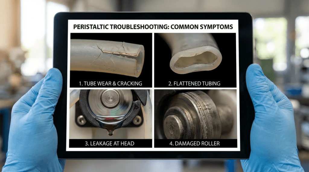
Troubleshooting Guide: Visual Forensics
When a hose fails, do not simply throw it away. The appearance of the failure tells the story:
- Clean Slit/Cut along the side: Usually fatigue failure. The hose has reached its natural end of life.
- Exploded/Shredded Hose: Over-pressure event. Check for closed valves or blockages.
- Internal Wall Erosion/Pitting: Chemical attack or abrasive wear from slip (under-occlusion).
- Outer Rubber Bubbling: Chemical incompatibility with the lubricant or heat damage.
Design Details & Calculations
Proper sizing prevents the majority of Peristaltic Troubleshooting: Symptoms. The following methodologies ensure the pump operates within a reliable envelope.
Sizing Logic & Methodology
The Golden Rule of Peristaltic Sizing: Select for Life, Not Just Flow.
1. Calculate Required Displacement per Revolution
Instead of looking at max flow, look at the displacement per revolution to keep RPM low.
Target RPM for Continuous Duty: < 30-40 RPM (depending on pump size).
2. Suction Condition Verification (NPSHa)
Even though these pumps are self-priming, you must verify the Net Positive Suction Head Available (NPSHa).
Calculation Consideration:
$$ NPSHa = P_{atm} + P_{static} – P_{friction} – P_{vapor} $$
However, for peristaltic pumps, you must also consider the Restitution Limit. Manufacturers provide a “Vacuum Capability” curve based on fluid viscosity and pump speed. If your suction lift requirement exceeds the curve for a given viscosity/RPM, the hose will not fill.
3. Pulsation Dampener Sizing
Peristaltic pumps deliver flow in discrete “slugs.” To calculate the required dampener volume:
Rule of Thumb: Dampener Volume ≈ 10x to 15x the pump’s displacement per revolution.
Specification Checklist
To ensure a robust installation, include these items in the Division 11 or Division 43 specification:
- Materials: Explicitly state the hose material (e.g., “High-density EPDM reinforced with braided nylon”).
- Safety: “Pump shall include an integrated leak detection sensor wired to the motor control circuit to execute an emergency stop upon detecting fluid in the housing.”
- Maintenance: “Pump housing shall be equipped with a drain port and valve sized for rapid lubricant draining.”
- Connections: “Suction and discharge connections shall include flexible expansion joints to isolate pump vibration from rigid piping.”
Standards & Compliance
- API 676: While primarily for rotary positive displacement pumps in oil/gas, many principles apply to heavy-duty industrial hose pumps.
- Hydraulic Institute (HI): Refer to HI standards for Positive Displacement testing and definitions.
- NSF/ANSI 61: Mandatory for any hose pump dosing chemicals into potable water streams. Ensure the specific hose compound is certified, not just the pump brand.
Frequently Asked Questions
What is the typical lifespan of a peristaltic hose?
Hose life varies drastically by application and speed. In continuous duty applications running at moderate speeds (30-40% of max RPM), a high-quality hose should last 2,000 to 4,000 hours (3 to 6 months). In intermittent duty or low-pressure transfer, hoses can last significantly longer. Conversely, running a pump at high speed (near max RPM) against high pressure can reduce hose life to under 500 hours. Consistent premature failure is a primary Peristaltic Troubleshooting: Symptom indicating undersizing.
Why does my peristaltic pump lose flow over time?
Flow loss is typically caused by two factors: hose fatigue and wear. As the hose loses its elasticity (memory), it fails to return to its full round shape efficiently, reducing the volume of the suction pocket. Additionally, abrasive wear on the inner wall increases the internal diameter, while the hose wall thins, reducing compression. This leads to internal back-flow (slip). Shimming can temporarily correct this, but hose replacement is eventual.
How do I determine if I need a pulsation dampener?
If the discharge piping exceeds 10-15 feet, or if the system includes flow meters, check valves, or injection quills, a pulsation dampener is highly recommended. Peristaltic pumps produce high-amplitude, low-frequency pressure spikes. Without dampening, these spikes cause “pipe hammer,” affect flow meter accuracy (especially magnetic flow meters), and can mechanically fatigue downstream pipe joints.
What is the difference between a “tube pump” and a “hose pump”?
While the principle is the same, the construction differs. Tube pumps generally use non-reinforced tubing, operate dry (no casing lubricant), and are limited to low pressures (under 30-40 psi). They are used for low-flow metering. Hose pumps use reinforced rubber hoses, usually operate in a lubricant bath to dissipate heat, and can handle pressures up to 230 psi. Hose pumps are used for sludge transfer and high-pressure chemical dosing.
Why is my pump casing running extremely hot?
Excessive heat is a critical warning sign. It usually indicates one of three issues:
1. Low Lubricant: The shoe/roller friction is not being dissipated.
2. Over-Occlusion: The hose is being squeezed too hard, generating excess friction.
3. High Speed: The pump is running faster than the thermal limit of the design.
If the casing is too hot to touch, immediate shutdown and inspection are required to prevent hose melting or fire.
Can peristaltic pumps run dry?
Yes, peristaltic pumps can run dry without damage to the mechanical components of the pump (unlike progressive cavity or centrifugal pumps). However, the hose itself still generates heat due to friction and compression. While short periods of dry running are acceptable, extended dry running can overheat the hose if the heat is not dissipated, shortening its life.
Conclusion
Key Takeaways for Engineers & Operators
- Speed Kills: The #1 cause of troubleshooting headaches is undersizing the pump and running it too fast. Keep continuous duty pumps below 30-40% of max RPM.
- Suction Matters: Just because it *can* self-prime doesn’t mean it should struggle. Ensure suction lines are large diameter and short to allow hose restitution.
- Analyze the Hose: Don’t just trash a failed hose. Inspect it. A burst implies over-pressure; a slit implies fatigue; sponginess implies chemical attack.
- Shim Correctly: Do not over-shim to compensate for a worn hose. This destroys bearings and wastes energy.
- Containment is Mandatory: Hoses are wear items. They will fail. Always design with leak detection and spill containment.
Mastering Peristaltic Troubleshooting: Symptoms requires a shift in perspective from reactive maintenance to proactive engineering. By understanding the physics of occlusion, restitution, and pulsation, engineers can specify systems that maximize hose life and minimize operator exposure to hazardous fluids.
When selecting a peristaltic pump, remember that the lowest capital cost often results in the highest operational headache. A properly sized, slower-running pump with correct suction hydraulics will provide years of reliable service in even the most difficult sludge and chemical applications. When symptoms arise, use the forensics of the failed component to identify the root cause—be it thermal, chemical, or mechanical—and adjust the operating parameters accordingly.