Progressive Cavity Wet Well Design and Minimum Submergence to Prevent Vortexing
Introduction to PC Pump Intake Hydraulics
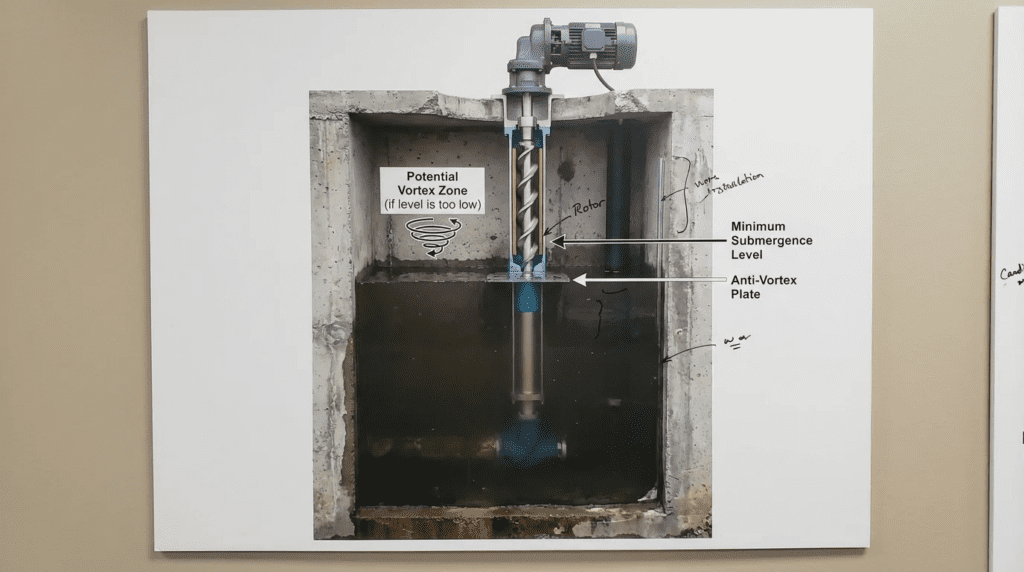
One of the most persistent and expensive failure modes in municipal wastewater treatment plants involves the premature destruction of progressive cavity (PC) pump stators. While often blamed on “bad rubber” or manufacturing defects, a significant percentage of these failures are actually hydraulic issues rooted in the civil and mechanical design of the suction side. Specifically, engineers often overlook the critical relationship between Progressive Cavity Wet Well Design and Minimum Submergence to Prevent Vortexing. When a PC pump ingests air due to vortex formation, the lubricating film between the rotor and stator breaks down, leading to rapid heat generation, rubber hardening, and catastrophic seizure.
Progressive cavity pumps are the workhorses of the wastewater industry for handling thickened sludge, polymer, and dewatered cake. Unlike centrifugal pumps, which suffer performance drops when entraining air, PC pumps are positive displacement devices that will attempt to compress the entrained air, causing noise, vibration, and inconsistent dosing. However, the most severe consequence is thermal damage. Because PC pumps rely on the pumped fluid to lubricate the interference fit between the metal rotor and the elastomeric stator, even small amounts of air entrainment from surface vortices can reduce stator life by 50% or more.
This article provides a rigorous technical analysis for consulting engineers and plant superintendents. It moves beyond basic “rules of thumb” to explore the hydraulic standards (ANSI/HI 9.8), the physics of non-Newtonian sludge flow, and the specific geometric configurations required to ensure process reliability. We will define how to calculate minimum submergence, design intake structures to suppress rotation, and select control strategies that prevent the formation of air-entraining vortices.
How to Select and Specify for Intake Performance
Proper specification of the wet well and intake piping is just as critical as specifying the pump itself. The interaction between the fluid rheology and the physical geometry of the sump determines the success of the installation.
Duty Conditions & Operating Envelope
The first step in Progressive Cavity Wet Well Design and Minimum Submergence to Prevent Vortexing is defining the fluid characteristics. In wastewater applications, sludge is rarely water-like; it is often thixotropic and shear-thinning. This affects how vortices form and decay.
- Viscosity and Solids Content: As solids concentration increases (e.g., from 1% WAS to 6% TWAS), the effective viscosity increases. Higher viscosity fluids dampen vortex formation but also increase entrance losses, requiring greater Net Positive Suction Head available (NPSHa).
- Flow Turndown: PC pumps often operate on VFDs with wide turndown ratios (10:1 or higher). The wet well design must prevent vortexing at maximum flow (runout conditions) while preventing solids deposition (sanding out) at minimum flow.
- Temperature: Sludge temperature variations affect viscosity. Cold sludge creates higher friction losses in the suction line, which increases the vacuum at the pump inlet. If the submergence is insufficient to overcome this vacuum and the entrance losses, the pump may cavitate.
Materials & Compatibility
While the wet well is typically concrete, the intake components (suction piping, bell mouths, and anti-vortex plates) must be compatible with the environment.
- Suction Piping: For corrosive environments or aggressive chemical dosing applications, 316 Stainless Steel or Schedule 80 PVC are common. However, the interior surface roughness is critical. Rough pipe interiors increase friction, lowering the pressure at the eye of the pump, which can promote gas release from solution (gaseous cavitation).
- Anti-Vortex Plates: If an existing wet well has insufficient submergence depth, an anti-vortex plate (or “suction umbrella”) may be required. These should be fabricated from materials resistant to the specific sludge chemistry to prevent corrosion that could eventually lead to structural failure and pump ingestion of debris.
Hydraulics & Process Performance
The core of the specification lies in the hydraulic design. Engineers must calculate the localized velocity at the intake.
- Bell Mouth Velocity: To minimize vortex formation, the velocity at the inlet bell mouth should typically be kept below 3.5 ft/s (1.1 m/s), significantly lower than standard pipe velocities.
- NPSHa Margins: PC pump manufacturers often quote Net Positive Suction Head required (NPSHr) based on water. When pumping sludge, engineers must apply a safety margin (often 3 to 5 feet or more) to the NPSHa calculation to account for the rheological differences and gas content in the sludge.
- Air Handling: PC pumps can theoretically handle high percentages of gas. However, “handling” does not mean “surviving long-term.” The specification must limit air entrainment to negligible levels to preserve the stator elastomer.
Installation Environment & Constructability
Physical constraints often dictate design. Retrofits are particularly challenging where the wet well footprint cannot be expanded.
- Wall Clearance: Placing a suction pipe too close to a vertical wall induces rotational flow (pre-swirl) which accelerates vortex formation. Design standards usually dictate a clearance, but in tight retrofits, engineers may need to specify flow straighteners or baffles.
- Floor Clearance: The distance between the intake bell and the floor is critical. Too close, and entrance losses skyrocket; too far, and the effective submergence is reduced, increasing vortex risk.
Reliability, Redundancy & Failure Modes
In the context of Progressive Cavity Wet Well Design and Minimum Submergence to Prevent Vortexing, reliability is achieved by preventing the conditions that cause dry running.
- Dry Run Protection: This is a mandatory specification item. Modern PC pumps should be specified with stator temperature probes (thermistors) drilled into the elastomer or flow switches on the discharge. However, these are reactive. Proper level control based on calculated minimum submergence is proactive.
- Vortex Breakers: In critical applications with variable levels, passive mechanical vortex breakers (floor-mounted vanes) significantly increase the reliability of the system by physically disrupting the rotation of the fluid column.
Controls & Automation Interfaces
The control system is the final line of defense against vortex-induced failure.
- Level Control Logic: SCADA systems must be programmed with a “Low Level Cutout” that is physically higher than the calculated minimum submergence depth ($S_{min}$). This setpoint should not be arbitrary; it must be derived from the hydraulic calculations.
- Speed Reduction: An advanced control strategy involves linking the VFD speed to the wet well level. As the level approaches the minimum submergence zone, the pump speed can be automatically reduced to lower the intake velocity, thereby suppressing vortex formation and allowing the tank to be pumped lower without air entrainment.
Maintainability, Safety & Access
Operators need to access the wet well for cleaning, as sludge tanks invariably accumulate grit and rag balls.
- Confined Space Entry: Vortex breakers and suction baffles create obstruction. Designs should ensure these components are robust enough to withstand high-pressure washdowns but positioned so they don’t trap rags that require manual removal.
- Cleanout cycles: If the design successfully prevents vortexing but leaves dead zones in the corners of the wet well (due to conservative square tank design), solids will accumulate and eventually slough off, choking the pump. Fillets and benching are recommended to direct solids toward the intake.
Lifecycle Cost Drivers
The cost of poor intake design is rarely captured in CAPEX. It appears in OPEX as:
- Stator Replacement: A stator failing every 6 months due to micro-dry-running costs significantly more than a proper concrete fillet or baffle installation.
- Energy Efficiency: Vortexing introduces air, which expands on the suction side and compresses on the discharge side. Compressing air is energy-intensive and inefficient in a hydraulic system. Eliminating air entrainment improves specific energy consumption.
Intake Configurations and Application Matrix
The following tables provide a framework for selecting the appropriate intake geometry and applying it to various wastewater process streams. Table 1 compares physical intake designs, while Table 2 analyzes application suitability based on sludge characteristics.
| Intake Configuration | Primary Strengths | Typical Applications | Limitations & Considerations | Relative Maintenance |
|---|---|---|---|---|
| Straight Pipe (No Bell) | Lowest installation cost; simple fabrication. | Small dosing pumps; low flow scenarios. | High entrance velocity leads to high vortex potential. High entrance head loss. Not recommended for primary sludge. | Low, but pump wear is higher. |
| Flared Bell Mouth | Reduces inlet velocity; streamlines flow; minimizes entrance losses (K factor ~0.1). | Standard municipal sludge transfer; TWAS; Digestate. | Requires more vertical clearance from floor ($C approx 0.3D$ to $0.5D$). slightly higher capital cost. | Low. |
| Formed Suction Intake (FSI) | Corrects poor approach flow; ideal for confined spaces where ideal straight runs aren’t possible. | Retrofits; lift stations with limited footprint. | High initial cost. Must be specifically designed for the pump capacity. | Moderate (ragging potential in vanes). |
| Trench-Type Intake | Allows for minimal submergence; excellent solids transport; minimizes dead spots. | High-solids loading; Scum pumping; Primary sludge. | Complex civil construction. Requires precise cleaning velocity calculations. | High (cleaning trench required). |
| Suction Umbrella / Plate | Allows pumping to very low liquid levels; suppresses surface vortices mechanically. | Decanting; Batch tanks requiring near-total emptying. | Can be prone to clogging with rags if gap is too small. Difficult to inspect beneath the plate. | Moderate. |
| Application / Fluid | Viscosity / Solids Profile | Vortex Risk Factor | Critical Design Constraint | Recommended Safety Factor on Submergence |
|---|---|---|---|---|
| Primary Sludge | High solids (3-6%); Heavy trash/grit loading. | Moderate | Solids settling. Velocity must be maintained to prevent septic conditions. | 1.3x HI Standard |
| Thickened WAS (TWAS) | High viscosity; shear-thinning; non-Newtonian behavior. | Low (Viscosity dampens swirl) | NPSHa. High friction losses in suction line. | 1.1x HI Standard |
| Polymer Solution | Extremely slippery; variable viscosity. | High (Slippery fluid sustains rotation) | Air entrainment destroys metering accuracy. | 1.5x HI Standard |
| Digested Sludge | Lower viscosity than TWAS; often warmer. | High (Gas breakout) | Entrained gas + vortex air = cavitation. | 1.5x HI Standard |
Engineer & Operator Field Notes
Real-world operation often deviates from theoretical design. The following sections outline practical strategies for managing Progressive Cavity Wet Well Design and Minimum Submergence to Prevent Vortexing in the field.
Commissioning & Acceptance Testing
Commissioning a PC pump system requires distinct protocols compared to centrifugal systems. A “bucket test” or flowmeter verification is insufficient.
- The Water vs. Sludge Paradox: Acceptance testing is frequently performed with clear water. Water has a much lower viscosity than sludge. A wet well design that does not vortex with water might still fail with sludge due to different flow patterns, or conversely, water might vortex more easily than thick sludge. However, if vortexing is observed during water testing (Type 3 or higher per HI 9.8), it is a critical failure that must be addressed before sludge introduction.
- Vacuum Gauge Baseline: During commissioning, install a compound pressure/vacuum gauge on the suction flange. Record the suction pressure at various speeds and tank levels. This establishes a baseline for the “clean” system. An increase in vacuum over time indicates suction line fouling; a sudden drop in vacuum accompanied by noise often indicates air entrainment via vortexing.
Common Specification Mistakes
Engineers reviewing submittals or writing RFPs should watch for these errors:
Correction: The cutout must be calculated based on the minimum submergence required to prevent vortexing above the bell mouth. Placing the cutout at the centerline guarantees vortexing (and likely air binding) before the pump stops.
- Ignoring Eccentric Reducers: When reducing pipe size from the wet well suction line to the pump inlet, eccentric reducers with the flat side on top are mandatory. Concentric reducers trap air pockets at the top of the pipe, which can slug into the pump, causing momentary dry runs.
- Distance from Walls: Placing the suction bell too close to a corner or back wall ($< 0.5D$) restricts flow and creates uneven velocity profiles, leading to subsurface vortices that are invisible from the operating deck but damaging to the pump.
O&M Burden & Strategy
Operational strategies can mitigate minor design flaws.
- Visual Inspection: Operators should periodically inspect the wet well surface during pump operation. A “dimple” on the surface (Type 1 or 2 vortex) is generally acceptable. A distinct dye core or sucking sound (Type 5 or 6) requires immediate intervention.
- Preventive Maintenance: Inspect the suction bell and wet well floor during cleanouts. Scour marks or localized erosion on the concrete floor directly under the bell indicate excessive inlet velocities or insufficient clearance, suggesting a need for a baffle plate or bell replacement.
Troubleshooting Guide
When a PC pump exhibits flow loss or noise, the wet well is often the culprit.
- Symptom: Popping/Cracking Noise. This is the sound of air bubbles imploding (cavitation) or being compressed. Check: Is the wet well level low? Is there a visible vortex? Is the suction strainer clogged?
- Symptom: Premature Stator Wear. If the stator rubber is hard and brittle, it suggests heat damage from dry running. Check: Review SCADA trends. Does the level drop below the critical submergence point before the pump shuts down?
- Symptom: Fluctuating Amperage. As the pump ingests slugs of air, the torque load drops momentarily. Check: Look for rhythmic amperage dips correlating with surface swirls in the tank.
Design Details and Sizing Methodology
To accurately determine the requirements for Progressive Cavity Wet Well Design and Minimum Submergence to Prevent Vortexing, engineers should follow a structured calculation path based on ANSI/HI 9.8 (Pump Intake Design).
Sizing Logic & Methodology
The Hydraulic Institute provides the gold standard for intake design. While primarily focused on rotodynamic pumps, the physics of vortex formation applies to positive displacement pumps as well.
Step 1: Determine Bell Diameter (D)
The suction bell diameter should be sized to achieve an inlet velocity of 3.0 to 5.0 ft/s (0.9 to 1.5 m/s).
Equation: $D = sqrt{frac{4Q}{pi V}}$
Where $Q$ is flow and $V$ is target velocity.
Step 2: Calculate Minimum Submergence ($S$)
The minimum submergence ($S$) is the depth from the liquid surface to the inlet of the suction bell. HI 9.8 recommends:
Equation: $S = D (1.0 + 2.3 F_D)$
Where $F_D$ is the Froude number: $F_D = frac{V}{sqrt{gD}}$
($V$ = velocity at the face of the bell, $g$ = gravitational acceleration, $D$ = Bell OD).
Specification Checklist
Ensure these items are included in the Section 11300 or 11350 specifications:
- Bell Mouth Requirement: “Suction intake shall be equipped with a flared bell mouth designed to reduce entrance velocity to max 3.5 ft/s.”
- Clearance Dimensions: Specify floor clearance ($C$) between $0.3D$ and $0.5D$. Specify back wall clearance ($B$) at approx $0.75D$.
- Vortex Suppression: “If minimum submergence cannot be met due to structural constraints, a stainless steel anti-vortex plate or grating shall be installed.”
- Testing: “Contractor shall demonstrate vortex-free operation at the lowest operating level during the Site Acceptance Test (SAT).”
Standards & Compliance
- ANSI/HI 9.8 (Rotodynamic Pumps for Pump Intake Design): Although titled for rotodynamic pumps, this is the industry standard for intake geometry and vortex prediction.
- ANSI/HI 11.6 (Rotodynamic Submersible Pumps: Hydraulic Performance, Hydrostatic Pressure, Mechanical, and Electrical Acceptance Tests): Relevant for testing protocols.
- NFPA 820: Standard for Fire Protection in Wastewater Treatment and Collection Facilities. Ensure that wet well design and ventilation meet classification requirements if the sludge produces methane.
Frequently Asked Questions
What is a Progressive Cavity pump’s tolerance for air entrainment?
Progressive Cavity (PC) pumps are generally more tolerant of air than centrifugal pumps and will not lose prime instantly. However, entrained air is compressible. As the rotor turns, the air compresses, generating heat. Since the stator relies on the pumped fluid for cooling and lubrication, continuous air entrainment (even as low as 2-5%) creates “dry run” conditions in localized areas of the stator, leading to rapid rubber degradation and premature failure. It also destroys metering accuracy in polymer or dosing applications.
How do you calculate minimum submergence for sludge?
Start with the ANSI/HI 9.8 formula: $S = D (1.0 + 2.3 F_D)$, where $D$ is the bell diameter and $F_D$ is the Froude number based on inlet velocity. Because sludge behaves differently than water (higher viscosity, non-Newtonian), engineers should apply a safety margin. A common practice for Progressive Cavity Wet Well Design and Minimum Submergence to Prevent Vortexing is to multiply the HI 9.8 result by 1.3 to 1.5 for thickened sludge applications to ensure adequate head pressure to fill the pump cavities without cavitation.
What is the difference between surface and subsurface vortices?
Surface vortices (Type 1-6) originate at the liquid surface and extend down to the intake, potentially drawing in air. These are visible to operators. Subsurface vortices originate from the floor or walls of the wet well and enter the intake. These are often invisible from the surface but cause fluctuating structural loads, vibration, and cavitation-like damage. Proper wall and floor clearances ($0.3D$ to $0.75D$) are designed specifically to prevent subsurface vortices.
Can I use a straight pipe instead of a bell mouth for a PC pump intake?
While possible for small dosing pumps, using a straight pipe for larger transfer pumps is bad engineering practice. A straight pipe has high entrance losses (K factor ~1.0) compared to a bell mouth (K factor ~0.1). This high entrance loss reduces the NPSHa. Furthermore, the sharp edge of a straight pipe accelerates the fluid rapidly, creating a high-velocity gradient that promotes vortex formation. A bell mouth smoothens the acceleration, reducing the risk of air entrainment.
How does a vortex breaker work?
A vortex breaker is a mechanical device, often a cross-shaped vane or a horizontal plate, placed at the inlet of the suction pipe. It does not stop the suction, but it physically blocks the organized rotation of the fluid column. By disrupting the “swirl,” it prevents a coherent air core from extending from the surface into the pump intake, allowing the pump to operate at lower submergence levels than would otherwise be possible.
Why is wet well geometry critical for Progressive Cavity pumps?
PC pumps are positive displacement pumps, meaning they pull a strong vacuum. If the wet well geometry restricts flow (e.g., intake too close to a wall), the pump will fight against this resistance. This can cause the formation of localized low-pressure zones where dissolved gas releases from the sludge (gaseous cavitation) or where vortices form. Proper geometry ensures smooth, laminar flow into the pump, maximizing stator life and energy efficiency.
Conclusion
Key Takeaways
- Physics Matters: PC pumps are positive displacement, but they are not immune to inlet hydraulics. Air entrainment kills stators via heat generation.
- Standard of Care: Use ANSI/HI 9.8 as the baseline for submergence calculations, but apply safety factors (1.3x – 1.5x) for viscous sludge.
- Velocity Control: Maintain intake bell velocities below 3.5 ft/s to minimize vortex potential.
- Geometry: Adhere to floor clearance ($0.3-0.5D$) and wall clearance ($0.75D$) ratios to prevent subsurface vortices.
- Protection: Always specify dry-run protection (temperature or flow) and set SCADA low-level cutouts based on calculated submergence, not arbitrary tank elevations.
The successful deployment of a progressive cavity pump depends as much on the civil and mechanical design of the wet well as it does on the pump manufacturing quality. By focusing on Progressive Cavity Wet Well Design and Minimum Submergence to Prevent Vortexing, engineers can eliminate one of the most common causes of premature pump failure.
Designing for the worst-case scenario—typically high viscosity sludge at low tank levels—ensures operational resilience. Rather than relying solely on the pump’s ability to “handle” air and solids, the goal should be to provide a hydraulic environment where the pump is always flooded with a solid column of fluid. Through proper sizing of bell mouths, adherence to Hydraulic Institute spacing standards, and intelligent control integration, municipalities can shift from a reactive maintenance cycle of stator replacements to a proactive reliability model that minimizes lifecycle costs.