Control Valves for Chemical Systems: Compatibility and Safety Considerations
INTRODUCTION
One of the most dangerous and costly mistakes an engineer can make in municipal or industrial water treatment design is treating chemical feed piping like standard water infrastructure. Specifying a generic 316 stainless steel valve for a seemingly routine disinfection or coagulation process frequently results in rapid, catastrophic failure. Dealing with Control Valves for Chemical Systems: Compatibility and Safety Considerations requires a specialized approach that accounts for aggressive corrosion, exothermic reactions, off-gassing, and highly viscous fluids. The consequences of improper valve specification are not merely operational nuisances; they result in hazardous chemical spills, EPA compliance violations, compromised operator safety, and severe plant downtime.
In modern water and wastewater treatment, control valves are deployed across a vast array of chemical applications. These include sodium hypochlorite and chlorine gas for disinfection, ferric chloride and alum for coagulation, caustic soda and sulfuric acid for pH adjustment, and complex polymer blends for sludge dewatering. Operating environments range from climate-controlled chemical building galleries to exposed, harsh outdoor tanks subject to massive temperature swings.
Engineers consistently underestimate the combined effects of concentration, temperature, and fluid velocity on valve wetted materials. A material that perfectly handles 98% sulfuric acid at ambient temperature may be completely destroyed by 10% sulfuric acid or when temperatures elevate slightly due to process friction or solar radiation. Furthermore, poor hydraulic sizing often leads to cavitation, which aggressively accelerates corrosion by constantly stripping away the passivating layers of metallic valves.
This article provides a comprehensive, unbiased engineering framework for selecting, specifying, and maintaining control valves in chemical dosing and transfer applications. It will guide design engineers, plant managers, and utility decision-makers through critical material selection matrices, precise hydraulic sizing methodologies, safety-centric installation protocols, and lifecycle maintenance strategies to ensure reliable, leak-free chemical control.
HOW TO SELECT / SPECIFY
Selecting control valves for chemical service is an iterative process. It requires balancing hydraulic control requirements against strict material compatibility constraints and stringent safety protocols. The following criteria form the foundation of a robust specification.
Duty Conditions & Operating Envelope
The operating envelope of a chemical control valve dictates its fundamental design. Engineers must define the maximum, minimum, and normal flow rates to establish the required turndown ratio. Chemical dosing often requires exceptionally high turndown (e.g., 50:1 or greater) to accommodate seasonal variations in water quality or plant flow.
Pressure drops (ΔP) across the valve must be carefully calculated. High pressure drops in volatile chemicals like sodium hypochlorite or hydrogen peroxide can trigger localized flashing, leading to off-gassing and vapor locking. Furthermore, engineers must consider the specific gravity and viscosity of the chemical. Heavy liquids like 50% sodium hydroxide (caustic soda) or viscous emulsions like liquid polymers behave vastly differently than water, altering the valve’s effective flow coefficient (Cv) and creating higher frictional losses.
Future capacity must also be considered. Over-sizing a valve for “future plant buildout” is a common error that forces the valve to operate below 10% open during its early lifecycle. This leads to severe seat wear, poor control resolution, and “hunting” as the actuator struggles to maintain the setpoint.
Materials & Compatibility
Material selection is the most critical factor when addressing Control Valves for Chemical Systems: Compatibility and Safety Considerations. Wetted parts (body, trim, and seals) must be resilient to the specific chemical at its maximum expected temperature and concentration.
- Metals: While 316L Stainless Steel is common for mild chemicals, aggressive media require exotic alloys. Alloy 20 is highly effective for sulfuric acid. Hastelloy C-276 offers broad resistance against severe corrosives and chlorides. Titanium is often the only acceptable metal for wet chlorine gas or high-concentration sodium hypochlorite.
- Plastics & Linings: Solid thermoplastics like PVC, CPVC, and PVDF (Kynar) are heavily utilized in municipal chemical feed due to their low cost and excellent resistance to hypochlorite and acids. However, they suffer from low pressure/temperature limits and mechanical fragility. For higher pressures, carbon steel or ductile iron bodies lined with PTFE or PFA provide the mechanical strength of metal with the ultimate chemical resistance of fluoropolymers.
- Elastomers: Seal failures are the leading cause of chemical leaks. EPDM is excellent for caustic and dilute acids but fails rapidly in hydrocarbons. FKM (Viton) is ideal for concentrated acids but fails in caustic environments. PTFE provides near-universal compatibility but lacks the elasticity needed for certain diaphragm or seat designs, requiring energized or composite seal configurations.
Do not assume that because a material handles a high-concentration chemical, it will handle a dilution. For example, carbon steel is generally acceptable for handling >98% concentrated sulfuric acid because it forms a protective iron sulfate film. However, if the acid is diluted to 90% or lower, it will rapidly corrode the carbon steel pipe and valve body. Always verify compatibility at the exact process concentration.
Hydraulics & Process Performance
The valve’s inherent flow characteristic—typically linear or equal percentage—must match the process dynamics. For pH control systems (which follow a logarithmic curve), an equal percentage trim is almost always required to achieve stable control loops. For simple flow proportioning of coagulants, a linear characteristic is usually sufficient.
Engineers must evaluate the potential for cavitation and choked flow. When dosing chemicals into a high-pressure main or operating with a large pressure differential, localized pressure drops inside the valve can fall below the chemical’s vapor pressure. In chemical service, cavitation is disastrous because the micro-jets created by collapsing bubbles literally tear away the passivating oxide layers of metallic valves, resulting in simultaneous mechanical erosion and accelerated chemical corrosion.
Installation Environment & Constructability
Chemical control valves are often installed in congested piping galleries or hazardous containment areas. Space constraints must account for the removal of the valve actuator, access to the packing gland, and the ability to safely extract the valve from the line without spilling trapped chemicals.
Piping stress is a major concern, particularly when interfacing heavy metal valves with plastic (PVC/CPVC) piping systems. Plastic flanges can easily crack if unevenly torqued against a heavy, unsupported control valve. Structural supports must bear the weight of the valve and actuator independently of the plastic piping.
Additionally, electrical components (actuators, positioners, solenoids) must meet the environmental classification. If installed in a dry polymer preparation area, NEMA 4X or NEMA 7 (dust ignition-proof) enclosures may be required. In areas where corrosive vapors are present (e.g., near open ferric or hypochlorite tanks), all external actuator parts must be epoxy-coated or made of engineered polymers.
Reliability, Redundancy & Failure Modes
In chemical systems, you must design for when, not if, a failure occurs. The most common failure modes are stem packing leaks, diaphragm ruptures, and seat passing due to scaling or debris.
Fail-safe actions are a mandatory consideration. If air or power is lost, should the valve Fail Open (FO), Fail Closed (FC), or Fail Last Position (FL)? In almost all chemical dosing applications, valves must Fail Closed to prevent uncontrolled dumping of chemicals into the water supply, which could cause severe overdosing, toxic gas generation, or pH violations.
Redundancy strategies typically involve utilizing a duty/standby configuration for critical chemical lines. For highly hazardous chemicals (like chlorine gas or concentrated hydrofluosilicic acid), automated isolation valves are often installed upstream of the control valve, triggered to shut automatically upon detection of a leak or a major control deviation.
Controls & Automation Interfaces
Modern chemical control valves utilize smart digital positioners communicating via 4-20mA with HART, Profibus, or Ethernet/IP. These smart positioners are not merely for control; they are essential diagnostic tools.
Advanced positioners can monitor valve friction signatures over time. A sudden increase in stem friction often indicates that a chemical is crystallizing on the valve stem or that the packing is beginning to fail. Conversely, a loss of friction might indicate that the packing has completely blown out. Integrating these diagnostics into the plant SCADA system allows for predictive maintenance before a hazardous leak occurs.
Maintainability, Safety & Access
Operator safety is the paramount concern. Valves handling strong acids, caustics, or oxidizers must be installed with ergonomic access in mind. Operators should never have to use a ladder to stroke, adjust, or repair a valve handling a hazardous chemical.
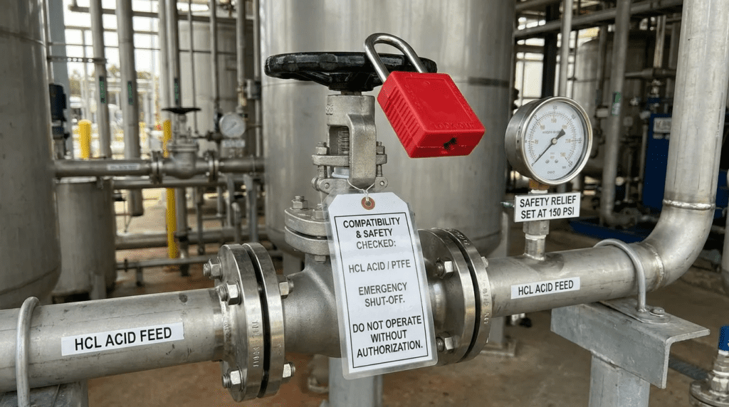
Clear, redundant isolation protocols are required. Every control valve must have manual isolation valves upstream and downstream, along with a safely piped drain/bleed valve to depressurize and evacuate the chemical line before maintenance begins. Furthermore, OSHA requires clear Lockout/Tagout (LOTO) provisions on both the fluid isolation valves and the pneumatic/electrical power sources feeding the control valve actuator.
For highly corrosive chemicals pumped under pressure, always specify PTFE or PVC safety shields (flange guards) around the control valve’s flanged connections. If a gasket blows out or a flange cracks, these guards diffuse the high-pressure chemical spray into a safe drip, preventing severe chemical burns to nearby operators.
Lifecycle Cost Drivers
The Total Cost of Ownership (TCO) for chemical control valves is heavily weighted toward operational expenditures (OPEX) and risk mitigation, rather than upfront capital expenditures (CAPEX).
Specifying a cheap PVC ball valve with an actuator might save thousands of dollars upfront compared to a PTFE-lined globe valve. However, if that PVC valve requires replacement every 12 months due to wear, causes erratic dosing that wastes costly chemicals, or breaks and causes an EPA fine for a chemical spill, the TCO is vastly higher.
Lifecycle cost analysis must factor in:
- Frequency of soft goods replacement (diaphragms, seats, packing).
- Cost of wasted chemical due to poor control resolution or internal leakage.
- Labor hours required for complex rebuilds vs. simple cartridge replacements.
- The financial risk of catastrophic failure (downtime, safety incidents, cleanup).
COMPARISON TABLES
The following tables provide a framework for evaluating different valve technologies and mapping them to specific chemical service applications. Use these tables to quickly identify best-fit solutions while avoiding known operational pitfalls.
Table 1: Control Valve Technologies for Chemical Service
| Technology / Type | Key Features & Wetted Parts | Best-Fit Applications | Limitations / Considerations | Typical Maintenance Profile |
|---|---|---|---|---|
| Lined Globe Valves | Ductile iron/steel body with thick PTFE/PFA lining. Bellows seal stems. | Aggressive acids (Sulfuric, Nitric), highly corrosive organics, high temp. | High initial CAPEX. Bulky and heavy. Sensitive to particulate abrasion. | Low. Bellows replacement every 5-7 years if cycled heavily. |
| Diaphragm Valves | Plastic (PVDF/PVC) or lined metal body. PTFE/EPDM diaphragm isolates stem. | Sodium hypochlorite, scaling chemicals, liquids with suspended solids. | Limited pressure capabilities (typically <150 psi). Poor control resolution at low flows. | High. Diaphragm requires preventative replacement every 1-3 years. |
| V-Port Ball Valves (Plastic/Lined) | Characterized V-notch ball. High rangeability. Ceramic or PTFE liners. | Caustic soda, high-flow chemical transfer, moderate precision dosing. | Cavities around ball can trap off-gassing chemicals (hypo) causing vapor lock or cracking. | Moderate. Seat replacement every 3-5 years. Packing adjustment required. |
| Pinch Valves | Full port elastomer sleeve (EPDM, Natural Rubber) pinched by mechanism. | Liquid polymers, lime slurry, powdered activated carbon (PAC). | Very poor precision at low flows. Sleeves can rupture without warning. Large footprint. | Moderate. Sleeve replacement every 1-2 years. Easy to maintain. |
Table 2: Chemical Application Fit Matrix
| Chemical Process | Key Process Constraints | Primary Wetted Materials | Recommended Valve Type | Relative Cost |
|---|---|---|---|---|
| Sodium Hypochlorite (12.5%) | Severe off-gassing, crystalizes on moving parts, highly corrosive. | Titanium, PVDF, PVC, PTFE seals. (NO Stainless Steel). | Vented V-port ball valve OR PTFE Diaphragm. | $$ – $$$ |
| Sulfuric Acid (>93%) | Exothermic reaction with water. Highly dangerous to operators. | Alloy 20, PTFE/PFA Lined Steel. | PTFE Lined Globe Valve with Bellows Seal. | $$$$ |
| Ferric Chloride / Alum | Low pH, prone to leaving sticky deposits, mildly abrasive. | CPVC, PVDF, Hastelloy trim, FKM (Viton). | Diaphragm Valve or Lined Plug Valve. | $$ |
| Liquid Polymer | High viscosity, shear sensitive, plugs easily. | 316SS (generally acceptable), EPDM/Rubber. | Pinch Valve or large CV Diaphragm Valve. | $$ |
| Caustic Soda (50% NaOH) | High specific gravity, freezes/crystallizes below 60°F. | 316SS, EPDM, PTFE. (NO FKM/Viton). | V-port Ball Valve (Heat traced if outdoors). | $$ |
ENGINEER & OPERATOR FIELD NOTES
Specification is only the first step. Ensuring that Control Valves for Chemical Systems: Compatibility and Safety Considerations are properly integrated requires strict oversight during commissioning and proactive maintenance strategies. The following field notes address common real-world challenges.
Commissioning & Acceptance Testing
Chemical control valves should undergo rigorous testing prior to introducing the actual process fluid. Factory Acceptance Tests (FAT) should verify stroke speed, fail-safe actuation upon power/air loss, and positioner calibration.
During the Site Acceptance Test (SAT), hydrotesting must be carefully managed. If testing a system intended for high-concentration sulfuric acid, the system must be completely dried and purged with nitrogen after hydrotesting. Introducing 98% sulfuric acid into a valve body containing residual testing water will cause an immediate, violent exothermic reaction, potentially rupturing the valve.
Key SAT checkpoints include:
- Verification of ANSI/FCI 70-2 seat leakage rates (Class IV, V, or VI).
- Verification of positive material identification (PMI) and Material Test Reports (MTRs) to ensure the contractor did not substitute 304SS for Alloy 20 or Hastelloy.
- Simulated loss of 4-20mA signal to ensure the valve fails closed smoothly without water hammer.
Common Specification Mistakes
The most frequent error in RFP documents is “copy-pasting” standard water valve specifications into the chemical system section. This leads to tragic mismatches, such as requesting a cast iron body with bronze trim for a hypochlorite line.
Another major mistake is ignoring the exterior environment. Engineers often specify wetted parts flawlessly but allow standard carbon steel actuators and mounting brackets. In a chemical building, ambient corrosive vapors will destroy the external actuator components within months. Epoxy coatings, stainless steel brackets, and fiberglass actuator housings are critical.
Over-sizing the valve Cv is rampant. Because chemical flow rates are often very low (gallons per hour, not gallons per minute), engineers must use micro-flow trims (e.g., splined plugs or needle-style trims). Specifying a 2-inch control valve when a 1/2-inch valve is hydraulically required forces the large valve to operate at 5% open, destroying the seats rapidly.
O&M Burden & Strategy
Reactive maintenance on chemical valves is unacceptable due to safety risks. Plants must transition to preventive and predictive strategies.
- Soft Goods Replacement: Diaphragms in sodium hypochlorite and ferric service should be replaced annually or bi-annually on a strict PM schedule, regardless of apparent condition. Embrittlement is invisible until it ruptures.
- Stroke Testing: Valves that sit in a single position for long periods (e.g., pH control valves that rarely move) should be “exercised” or stroke-tested partially every week to prevent stems from seizing due to scaling.
- Spares Inventory: Always maintain full repair kits (packing, seats, diaphragms) for critical chemical valves. For highly critical, customized valves (like exotic alloy globe valves), stocking a complete replacement valve is recommended due to potential 20+ week lead times.
Troubleshooting Guide
When a chemical valve begins to fail, the symptoms provide clear diagnostic clues:
- Symptom: Valve is “hunting” or oscillating wildly.
Root Cause: The valve is oversized, operating too close to the seat, or the positioner tuning parameters (PID) are aggressive. Alternatively, sticky deposits on the stem have increased static friction, causing “stiction” (the actuator builds up force, then the stem jumps past the setpoint). - Symptom: Chemical smell in the air near the valve, but no visible liquid leak.
Root Cause: Fugitive emissions passing through the stem packing. The packing needs to be re-torqued or replaced with a zero-emission environmental packing system (e.g., PTFE V-rings with live loading). - Symptom: Loss of flow control, but actuator is moving normally.
Root Cause: For plastic valves, the stem may have snapped inside the valve body, or a diaphragm has decoupled from the compressor stud. For metal valves, severe cavitation or corrosion has eroded the plug.
Operators sometimes close manual isolation valves downstream of a closed chemical control valve, trapping fluid between them. If the chemical is sodium hypochlorite, it naturally off-gasses oxygen. In a trapped space, this off-gassing creates immense pressure (thousands of PSI), inevitably bursting the plastic pipe or blowing out the valve packing. Always include pressure relief or venting mechanisms in isolated chemical lines.
DESIGN DETAILS / CALCULATIONS
Translating chemical flow requirements into physical valve dimensions requires rigorous mathematics. Using rule-of-thumb sizing for chemical systems often results in failure.
Sizing Logic & Methodology
Control valve sizing relies on calculating the flow coefficient ($C_v$). $C_v$ is defined as the number of US gallons per minute of water at 60°F that will flow through a valve with a 1 psi pressure drop.
For chemical liquids, the standard formula is modified by the specific gravity ($G$) of the chemical:
$C_v = Q times sqrt{G / Delta P}$
Where:
- $Q$ = Flow rate in GPM
- $G$ = Specific gravity of the chemical (Water = 1.0)
- $Delta P$ = Pressure drop across the valve ($P_1 – P_2$) in psi
Example Calculation:
An engineer needs to size a control valve for dosing 50% Caustic Soda ($G approx 1.53$) at a maximum flow rate of 10 GPM. The upstream pressure ($P_1$) is 50 psi, and the downstream pressure ($P_2$) at the injection point is 40 psi. The pressure drop ($Delta P$) is 10 psi.
$C_v = 10 times sqrt{1.53 / 10}$
$C_v = 10 times sqrt{0.153}$
$C_v = 10 times 0.391 = 3.91$
Design Margin: The calculated $C_v$ is 3.91. A standard engineering practice is to select a valve where the normal operating flow occurs at 60-70% of the valve’s total capacity. Therefore, the engineer should look for a valve trim with a maximum $C_v$ of approximately 6.0.
Specification Checklist
To ensure bulletproof procurement, every chemical control valve specification must include the following mandatory parameters:
- Process Fluid Details: Chemical name, concentration range (%), minimum/normal/maximum operating temperatures, and specific gravity.
- Hydraulic Data: P1 (inlet pressure), P2 (outlet pressure), maximum shutoff pressure, required maximum flow, and required minimum controllable flow.
- Valve Body Construction: Material standard (e.g., ASTM A351 CF8M, solid PVDF), flange rating (e.g., ANSI Class 150), and face-to-face dimensions (ISA 75.08).
- Trim & Soft Goods: Plug/seat material, inherent flow characteristic (linear/equal percent), and specific elastomer requirements (e.g., PTFE energized V-ring packing).
- Actuation & Controls: Power availability (pneumatic air pressure or 120VAC), fail-safe position (Fail Closed), and communication protocol (4-20mA HART).
- Safety Accessories: Flange guards, limit switches for definitive open/close indication, and manual override handwheels.
Standards & Compliance
Chemical control valve design must comply with several overarching standards to ensure safety and interoperability.
- ANSI/ISA-75 series: Dictates face-to-face dimensions, ensuring that a valve from Manufacturer A can physically replace a valve from Manufacturer B without altering the rigid chemical piping.
- ASME B16.34: Governs pressure-temperature ratings for metallic valves, establishing safe operating limits for given wall thicknesses and materials.
- ANSI/FCI 70-2: Specifies seat leakage classes. For hazardous chemicals, Class VI (bubble-tight shutoff utilizing soft seats) is highly recommended.
- ISO 15848: The standard for measurement, test, and qualification procedures for fugitive emissions from industrial valves. Specifying compliance to this standard ensures that toxic fumes (like chlorine or hydrogen sulfide) will not leak past the valve stem into the breathing zone of operators.
- OSHA 1910.119 (PSM): If the chemical handled falls under the Process Safety Management (PSM) standard (e.g., bulk chlorine gas), the valve must meet stringent documentation, management of change (MOC), and mechanical integrity requirements.
FAQ SECTION
What is the most critical factor when selecting control valves for chemical systems?
The absolute most critical factor is verifying material compatibility for the exact chemical, at its specific concentration and highest expected temperature. Control Valves for Chemical Systems: Compatibility and Safety Considerations hinge on understanding that a material resistant to a 98% concentrated acid might dissolve rapidly in a 10% dilution. Always consult comprehensive chemical compatibility charts for wetted parts (body, trim, seals) rather than assuming broad resilience.
Why do control valves in sodium hypochlorite service fail so frequently?
Sodium hypochlorite (bleach) creates two major challenges: it continuously off-gasses oxygen, and it leaves behind scale and crystallizations. Off-gassing can become trapped in the cavities of standard ball valves, causing pressure spikes that crack plastic valve bodies (vapor lock). The scaling damages valve stems and destroys soft seats. To prevent this, engineers should specify vented ball valves, diaphragm valves, or use PTFE wetted materials with self-flushing designs. See the [[Materials & Compatibility]] section.
What is the difference between equal percentage and linear flow characteristics?
A linear valve changes flow linearly with its stroke (e.g., 50% open equals 50% of maximum flow). It is used for basic proportional dosing. An equal percentage valve changes flow exponentially, meaning a 10% change in stroke yields a constant percentage increase in flow across the entire range. Equal percentage trims are highly recommended for chemical pH control because the pH scale is logarithmic; they help stabilize the control loop and prevent massive overshoots of acid or caustic.
How do you prevent cavitation in chemical dosing valves?
Cavitation occurs when the pressure drop across the valve causes the liquid to momentarily boil and collapse back into liquid, tearing apart the valve trim. To prevent it, you must limit the pressure drop across a single valve. If a massive pressure reduction is required, use multi-stage anti-cavitation trim, place two valves in series, or install an orifice plate downstream to share the pressure drop. Properly sizing the $C_v$ to keep the valve opening between 30-70% also mitigates high-velocity localized cavitation.
What are the best practices for chemical valve safety?
Safety best practices include: engineering the system to “Fail Closed” upon loss of power/air, utilizing zero-emission packing to prevent fugitive emissions of toxic gases, installing PTFE safety shields (flange guards) around connections, and providing double-block-and-bleed isolation layouts. Additionally, never install chemical valves overhead without proper access platforms, ensuring operators can easily apply Lockout/Tagout (LOTO) protocols.
How often should chemical control valves be maintained?
Maintenance frequency depends on the chemical severity. For hazardous scaling or crystallizing chemicals (hypochlorite, ferric chloride), soft goods (diaphragms, seats) should be replaced every 12-24 months preventatively. For clean, mild chemicals, maintenance intervals can extend to 3-5 years. However, all chemical valves should undergo regular stroke testing to ensure stems are not seizing. Refer to the [[O&M Burden & Strategy]] section for detailed guidance.
CONCLUSION
- Material Matching is Absolute: Never specify materials based on general assumptions. Concentration and temperature dramatically alter chemical aggressiveness. Confirm compatibility for body, trim, and seals independently.
- Size for Reality, Not the Future: Oversizing valve $C_v$ leads to poor control resolution, seat erosion, and control loop hunting. Select valves that operate within 30% to 70% of their travel under normal flow conditions.
- Fail-Safe Design is Mandatory: Chemical control valves must almost universally fail closed to prevent toxic overdosing, spills, and catastrophic process imbalances.
- Eliminate Fugitive Emissions: Utilize bellows seals, advanced PTFE live-loaded packing, or diaphragm isolation to protect plant personnel from airborne toxic off-gassing.
- OPEX Over CAPEX: Do not compromise on upfront valve quality. The cost of a specialized lined globe valve is negligible compared to the EPA fines, cleanup costs, and downtime caused by a ruptured cheap plastic valve.
Specifying Control Valves for Chemical Systems: Compatibility and Safety Considerations is a high-stakes engineering discipline that bridges process chemistry, fluid mechanics, and plant safety. Municipal and industrial water/wastewater systems rely on highly reactive, corrosive, and dangerous chemicals to ensure water purity and environmental compliance. Consequently, the valves that control these chemicals must be treated as critical safety assets, not standard plumbing fixtures.
Engineers and plant managers must approach selection systematically. Begin by accurately defining the hydraulic operating envelope—including specific gravity, viscosity, and potential for cavitation—to properly size the flow coefficient ($C_v$). Next, execute a rigorous material compatibility review, considering the exact concentration and temperature profiles of the chemical to select the appropriate metals, fluoropolymers, and elastomers. Finally, integrate the valve into a broader safety and control strategy that includes predictive diagnostics via smart positioners, ergonomic access for operators, and strict fail-safe parameters.
When in doubt, particularly with exotic chemicals, high temperatures, or extreme pressure drops, engineers should collaborate directly with valve manufacturers’ application specialists. Balancing the competing demands of hydraulic precision, chemical resilience, and lifecycle cost requires diligence, but a well-specified chemical control valve will provide decades of safe, reliable, and leak-free performance.