
Aeration Energy Optimization: Control Strategies That Reduce kWh Without Risk
Introduction
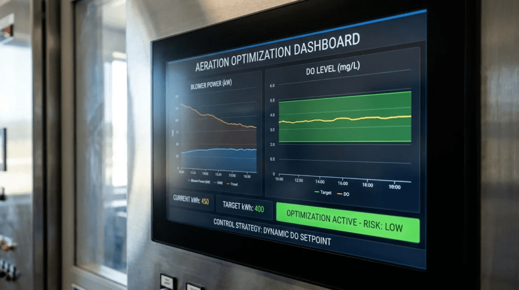
In municipal and industrial wastewater treatment, biological aeration typically accounts for 50% to 60% of total facility power consumption. As energy costs rise and sustainability commitments tighten, engineers are tasked with reducing operating expenditure. Reducing blower output indiscriminately leads to process failures — ammonia permit violations, poor settleability, filamentous growth — which is why the qualifier in Aeration Energy Optimization: Control Strategies That Reduce kWh Without Risk carries the weight.
Most oversights occur at the intersection of biological demand, aeration equipment limits, and automation logic. An efficient turbo blower is ineffective if throttled by poorly tuned hunting control valves, or if forced to operate against an artificially high header pressure. Moving from constant-speed operation to dynamic load-following aeration requires coordinated instrumentation, mechanical equipment, and control algorithms.
These strategies apply across suspended growth processes: conventional activated sludge, biological nutrient removal, sequencing batch reactors, and hybrid systems. This article provides a framework for designing, specifying, and implementing robust aeration control, covering most-open-valve pressure optimization, cascade dissolved oxygen control, and ammonia-based aeration control. It sits within the broader treatment of wastewater aeration systems, and assumes the equipment has been correctly sized in the first place.
How to Select and Specify
Duty Conditions & Operating Envelope
- Biological Loading Variation: Quantify diurnal, seasonal, and wet-weather profiles. The system must turn down during nocturnal low load without causing blower surge or falling below minimum mixing, typically in the range of 0.12 to 0.15 SCFM per square foot of basin floor.
- Airflow and Pressure Ranges: The strategy must operate within the blowers’ thermodynamic envelope. Plot system curves against blower performance at both summer and winter inlet conditions, since inlet air density changes the mass flow a given blower delivers.
- Modes of Operation: Specify steady-state operation, transition logic during blower sequencing, and fallback modes on instrument failure — typically reverting to flow-paced or fixed setpoints rather than to an undefined state.
Materials & Compatibility
- Sensors: Dissolved oxygen probes and ion-selective ammonia sensors operate in fouling mixed liquor. Specify luminescent optical DO sensors with durable sensing caps. Ammonia sensors should have robust housings with replaceable cartridges.
- Airflow Control Valves: Valves on the aeration drops see continuous modulating duty. Specify butterfly, iris, or V-port designs with stainless trim and seats rated for the elevated temperature of compressed air at the blower discharge.
- Actuators: Modulating actuators must be rated for continuous duty to avoid overheating under the constant micro-adjustments a control loop imposes.
Hydraulics & Process Performance
- Valve Authority: Authority is the ratio of the pressure drop across the valve at design flow to the total system pressure drop. Low authority means the valve barely influences flow until it is nearly shut, which produces a non-linear response and hunting. The valve must take a meaningful share of the system drop to control at all — and this requirement sits in direct tension with the pressure-minimization objective below, which is exactly why the two must be designed together rather than sequentially.
- Diffuser Flux: Respect the minimum and maximum airflow per diffuser. Below the minimum flux, commonly around 0.5 SCFM per fine-bubble diffuser, mixed liquor can enter and foul the element. Above the maximum, bubbles coalesce and transfer efficiency falls sharply.
- Process Constraints: In nutrient removal plants, the logic must prevent over-aeration in aerobic zones, because dissolved oxygen carried into the anoxic zone by the internal recycle suppresses denitrification.
Installation Environment & Constructability
- Sensor Placement: Install in representative zones. Avoid locations near influent baffles, directly above diffusers where bubble interference biases the reading high, and dead zones. Typical placement is one-third to one-half of the way along the basin, or at the zone effluent.
- Flowmeter Piping: Thermal dispersion and vortex meters require straight pipe runs upstream and downstream to establish a stable velocity profile. Take the requirement from the meter manufacturer and check it against the available pipe before the layout is fixed.
- Actuator Access: Valves are often elevated on drop pipes. Provide walkways or platforms so calibration and actuator replacement do not require scaffolding.
Reliability, Redundancy & Failure Modes
- Sensor Redundancy: For critical loops, use multiple sensors per zone with voting or median-select logic to discard outliers caused by ragging or sensor failure.
- Failsafe Positions: Specify explicit actuator behaviour on loss of signal or power. Failing in last position or failing open both have defensible logic; failing to an undefined position does not.
- Blower Protection: The primary failure mode in dynamic control is driving centrifugal blowers into surge. Surge protection must be hardwired and operate independently of the process optimization controller.
Controls & Automation Interfaces
- Cascade DO Control: Rather than modulating a valve directly on dissolved oxygen error, the DO controller calculates an airflow setpoint, and a secondary flow loop modulates the valve to achieve it. This decouples fast mechanical air dynamics from the slow biological oxygen uptake rate, which is the source of most hunting in single-loop designs.
- Most Open Valve (Pressure Minimization): The system monitors all valve positions and lowers the header pressure setpoint until the most open valve sits near full open. This removes the artificial restriction the blowers were pushing against and reduces power directly.
- Ammonia-Based Aeration Control: Adjusts the DO setpoint dynamically against measured ammonia. Feed-forward measures influent load; feedback measures effluent ammonia. The result is that air is spent when the nitrogen load requires it rather than continuously.
Maintainability, Safety & Access
- Auto-Cleaning: Specify air-blast cleaning on in-situ sensors. Periodic bursts prevent biofilm accumulation and extend manual cleaning intervals substantially.
- Calibration Access: Require retrieval mechanisms — swing arms or guide rails — that bring sensors onto the walkway without full fall-protection rigging.
- Isolation: Document electrical disconnects for actuators and isolation valves for flow meters on the P&ID.
Lifecycle Cost Drivers
- Baseline against optimized power: Capital cost for sensors, modulating valves, and programming is real and recoverable, but the payback depends entirely on the baseline. A plant already running cascade DO control has far less to gain than one running constant pressure with manual valves. Establish the baseline by measurement before estimating the return.
- Sensor Consumables: Include DO sensor caps and ammonia cartridges in the lifecycle analysis. These are recurring and predictable, and they are the item most often omitted from the business case.
The Savings Are in the Pressure, and the Worst Diffuser Sets It
Most-open-valve logic is the highest-return control strategy available to an aeration system, and it is also the one most often disappointing in practice. Understanding why requires seeing what actually sets the header pressure.
A blower must generate enough discharge pressure to overcome the static submergence of the diffusers, plus the pressure drop through the piping, the control valve, and the diffuser element itself. Most-open-valve logic attacks only one of those terms: it removes the artificial drop across a throttled valve by opening the valve and lowering the blower setpoint. That is genuine and worthwhile.
But the logic can only lower the header pressure until the most demanding zone runs out of valve. And what makes a zone demanding is usually not its biological load — it is the condition of its diffusers. A zone with fouled or scaled membranes has elevated dynamic wet pressure, so its valve must sit further open to pass the same airflow. Once that zone’s valve reaches full open, the pressure minimization stops, and every other zone continues to be fed at a pressure set by the worst grid in the plant.
Three consequences follow. First, diffuser condition and control strategy are the same project. Installing most-open-valve logic over a plant with one badly fouled zone buys a fraction of the available savings, and the diagnosis looks like a control problem when it is a mechanical one. Second, valve position is the diagnostic. Trend each zone’s valve position against its airflow. A zone whose valve has migrated from 50% to 80% open over months to deliver the same air has fouling diffusers, and the control system has been quietly compensating. That trend is the earliest and cheapest indicator of grid deterioration available. Third, the authority requirement and the pressure objective conflict, and the resolution is to size valves for adequate authority at design flow while accepting that most-open-valve logic will run them near open at reduced load — which means the valves must be characterized so control remains stable at high opening, where the inherent curve is flattest.
The practical sequence is therefore: assess and restore diffuser condition, then implement pressure minimization, then trend valve position permanently as the early-warning system. Reversing that order produces a control project that underdelivers and a maintenance problem that stays hidden.
Comparison Tables
| Control Strategy | Core Mechanism | Energy Savings Potential* | Instrumentation Required | Limitations / Risks |
|---|---|---|---|---|
| Constant Pressure / Manual Valves | Blower holds a fixed header pressure; operators adjust valves manually. | Baseline | Pressure transmitter, manual valves. | Substantial over-aeration during low diurnal load. |
| Direct DO to Valve (single loop) | DO probe modulates the airflow valve directly to a fixed DO setpoint. | Modest | DO probes, modulating valves, fixed pressure setpoint. | Prone to hunting. Does not address blower discharge pressure. |
| Cascade DO with Airflow Control | DO controller sets an airflow target; a secondary loop modulates the valve to meet it. | Moderate | DO probes, mass flowmeters, modulating valves. | Stable, but still operates at a fixed and artificially high header pressure. |
| Most Open Valve / Pressure Reset | Lowers the header pressure setpoint until the most open valve approaches full open. | Substantial | Valve position feedback, master controller, variable-speed blowers. | Requires adequate blower turndown. Savings capped by the worst diffuser grid. Surge risk if tuning is aggressive. |
| Ammonia-Based Aeration Control | Adjusts DO setpoints dynamically against measured ammonia. | Largest | Ammonia analyzers, full pressure-reset integration, advanced algorithms. | High sensor maintenance burden. Requires skilled staff and disciplined calibration, or the savings evaporate. |
*Relative to a fully manual, constant-pressure baseline. Actual savings depend heavily on the starting condition and on diffuser state; establish the baseline by measurement rather than adopting a published percentage.
| Facility Profile | Recommended Strategy | Key Driver / Constraint | Operator Skill Required | Relative Cost |
|---|---|---|---|---|
| Small plant, non-nutrient-removal | Cascade DO control | Keep it simple; limited maintenance bandwidth for advanced sensors. | Low to moderate | $ |
| Medium plant, conventional activated sludge | Cascade DO plus pressure reset | Blower pressure reduction justifies integration cost, provided diffusers are sound. | Moderate | $$ |
| Large plant, tight nitrogen limits | Ammonia-based control with pressure reset | Largest savings potential alongside strict nutrient compliance. | High; instrument technician required | $$$ |
| Oxidation ditches | DO and ORP phased control | Requires variable speed on surface aerators or rotor depth adjustment. | Moderate | $$ |
| Industrial, high and variable organic load | Feed-forward load control | Shock loads require pre-emptive aeration rather than reactive correction. | High | $$$ |
Engineer & Operator Field Notes
Commissioning & Acceptance Testing
- Factory testing: Require a simulation of the control logic. Force inputs — simulate a DO drop, a valve failure, an analyzer fault — to verify cascade loops, pressure reset, and blower sequencing respond without instability.
- Site testing: Include loop tuning under actual process conditions. Step-test the system: lower the DO setpoint, allow stabilization, then raise it and observe the response. Tune slightly overdamped, because a loop tuned for speed will hunt against the slower biological response.
- Valve and blower interaction: Verify that actuator stroke speeds align with blower ramp rates. If a valve closes faster than a centrifugal blower can decelerate, the blower moves toward surge. Coordinate actuator transit times with blower acceleration and deceleration parameters explicitly.
Do not rely solely on theoretical surge curves. During site testing, throttle valves manually under controlled conditions to approach the surge limit, document it via current draw and vibration, and set hard protective boundaries in the controller with a defined margin away from the measured line rather than the published one.
Common Specification Mistakes
- Assuming a linear valve response: Butterfly valves have a non-linear inherent characteristic, with most of the flow change occurring through the mid-stroke. A control loop expecting linear response will hunt at one end of travel and respond sluggishly at the other. Require signal characterization — a lookup table in the controller — to linearize the response.
- Ignoring valve authority: An undersized header or oversized valves leaves the valves operating near closed, where control is erratic. Size for adequate authority at design flow and characterize the response so that stability holds at the high openings pressure-reset logic will drive them to.
- Omitting deadbands: Pressure reset logic attempting to hold a valve at an exact position will hunt continuously. Specify a target band rather than a target value, so the logic acts only when the most open valve leaves the band.
- Treating diffuser condition as out of scope: The control project cannot deliver its modelled savings over a fouled grid.
O&M Burden & Strategy
- Probe cleaning: Even with auto-cleaning, optical DO sensors need periodic manual wiping. Ammonia sensors require more frequent attention, since biofilm alters diffusion rates and therefore the reading.
- Calibration drift: Optical DO caps degrade over time. Follow the manufacturer’s interval for coefficient updates or cap replacement. A probe reading artificially low drives the blowers to over-aerate, which destroys the intended saving silently — the plant pays for air it did not need and the instrument reports success.
- Valve position trending: Trend each zone’s valve position against airflow, and treat a rising position at constant flow as evidence of diffuser fouling rather than as normal drift.
Troubleshooting
- Oscillating DO: Typically aggressive tuning, mismatched actuator and blower speeds, or oversized valves. Reduce proportional gain, lengthen integral time, and verify that signal characterization is active.
- Blower surging or blowing off air: DO setpoints are being met, valves are pinching down, and the blower is being pushed up its curve toward surge. Implement or tune pressure reset so valves open further, and program minimum airflow constraints to override the DO loop where necessary.
- Sluggish response: Either biological — a shock or high organic load — or mechanical, such as actuator failure or a fouled blower inlet filter. Verify DO accuracy against a portable instrument and confirm from the flowmeter that air is actually reaching the basin.
Design Details / Calculations
Converting Biological Demand to Equipment Rating
The core calculation converts the actual oxygen transfer rate the biology demands into the standard oxygen transfer rate manufacturers use to rate diffusers and blowers.
- Calculate actual oxygen requirement (AOR). Oxygen for carbonaceous removal is commonly taken at 1.1 to 1.5 lb O2 per lb BOD removed, and for nitrification at approximately 4.6 lb O2 per lb ammonia nitrogen oxidized, less the credit recovered by denitrification where it occurs.
- Convert AOR to SOR. The relationship, in the form used by the ASCE clean water testing standard, is:
SOR = AOR ÷ { α × F × [ ( β × τ × Ω × C*∞,20 − C ) ÷ C*∞,20 ] × θ(T−20) }
- α — ratio of transfer in process water to clean water, commonly 0.4 to 0.7 depending on solids concentration and diffuser condition.
- F — fouling factor for the diffusers.
- β — salinity and dissolved solids correction, commonly 0.95 to 0.98.
- τ — temperature correction on saturation concentration.
- Ω — pressure correction for site elevation and diffuser submergence.
- C — operating dissolved oxygen concentration. This is the optimization lever: lowering the operating DO increases the driving gradient and reduces the required SOR, which is precisely the mechanism ammonia-based control exploits during low-load periods.
- C*∞,20 — saturation concentration at standard conditions.
- θ — temperature coefficient for transfer, commonly taken as 1.024.
- Determine airflow. Convert SOR to airflow using the standard oxygen transfer efficiency of the specific diffuser grid at its design submergence.
Engineers frequently apply a single alpha value across all load conditions. Alpha varies with organic loading, surfactant concentration, and diffuser flux. Size the blowers against the lowest credible alpha — generally the peak summer loading condition — and recognize that a control system compensating for a declining alpha will look like a control problem.
Specification Checklist
- Master control panel: a dedicated controller for aeration, communicating with local panels over an industrial protocol stated in the specification.
- Valve characterization: require the integrator to provide multi-point linearization curves converting flow requests into position signals based on the actual valve geometry supplied.
- Flowmeter turndown: specify a minimum turndown ratio adequate to measure airflow accurately at nocturnal low load, not just at design flow.
- Diffuser condition baseline: require dynamic wet pressure measurement at commissioning, per zone, as the reference against which future fouling is judged.
- Performance guarantees: where a proprietary algorithm is specified, require a guaranteed specific energy figure subject to clearly defined baseline conditions, including diffuser condition.
Standards & Compliance
- WEF Manual of Practice No. 32: Energy Conservation in Water and Wastewater Facilities, the baseline reference for aeration efficiency practice.
- ASCE/EWRI 2-06: Measurement of Oxygen Transfer in Clean Water, governing the testing that underlies any diffuser efficiency claim.
- ASCE/EWRI 18-18: in-process oxygen transfer testing, for verifying performance under actual conditions.
- ISA practice for P&ID development, loop tuning documentation, and operator interface design, so that the control strategy remains visible to the people running it.
FAQ
What does aeration energy optimization actually involve?
Integrating instrumentation, automated valves, and control logic — principally pressure minimization and ammonia-based setpoint adjustment — so the system delivers the oxygen the biology requires at the lowest achievable blower discharge pressure, without compromising permit limits or equipment life. It also involves confirming the mechanical condition of the diffusers, because the control system cannot outperform the grid it is feeding.
What is the difference between direct and cascade DO control?
Direct control uses a single loop in which DO error drives valve position. Because airflow is not measured, the loop cannot distinguish a valve problem from a process change, and it hunts. Cascade control uses two loops: the DO loop calculates a required airflow, and a faster flow loop adjusts the valve to deliver it. That separation of timescales is what makes cascade control stable.
How does pressure minimization save blower energy?
Blower power depends on both the volume moved and the pressure developed. Where valves are partially closed to control flow, the blower must generate additional pressure purely to push air through that restriction, and that pressure is wasted. Lowering the header setpoint until the most open valve approaches full open removes the artificial restriction. The saving is bounded by the zone with the highest dynamic wet pressure, which is usually the zone with the most fouled diffusers.
What are the risks of turning blowers down too far?
Operating a centrifugal blower below its minimum stable flow causes surge, in which flow momentarily reverses, producing severe vibration and potential damage to impellers and bearings. Separately, insufficient airflow can allow mixed liquor to enter fine-bubble diffusers, causing permanent fouling, and can fall below the minimum mixing requirement, allowing solids to settle.
How often do DO and ammonia sensors need maintenance?
Optical DO sensors typically need periodic manual wiping on a scale of weeks even with auto-cleaning active, with cap replacement on a multi-year interval. Ammonia sensors require more frequent calibration verification and cartridge replacement on a shorter cycle. Budget the labour explicitly, because the entire return on the project depends on the instruments remaining accurate.
Why do control valves hunt, and how is it fixed?
Hunting is a loop overcorrecting and never settling. In aeration systems the usual causes are aggressive tuning, oversized valves operating near closed, and failure to characterize the non-linear valve curve in the controller. The fix is step-testing and retuning, with signal characterization enabled, and in some cases reselecting the valve.
How does this relate to diagnosing a plant that cannot hold DO at all?
The two use the same instruments and much of the same logic, from opposite directions: optimization removes air the plant does not need, while troubleshooting finds out why air the plant is supplying is not transferring. Where a plant cannot hold setpoint despite full blower output, start with the diagnostic hierarchy in aeration troubleshooting for low DO. Where the question is whether the equipment was adequately sized in the first place, the framework is in aeration system sizing and turndown design.
Conclusion
- Decouple the Timescales: cascade control separates slow biological oxygen uptake from fast mechanical airflow dynamics, which is what eliminates hunting.
- Pressure is Power: pressure minimization is the highest-return strategy, because forcing blowers to push air through partially closed valves wastes energy continuously.
- The Worst Diffuser Caps the Saving: pressure reset stops at the zone with the highest dynamic wet pressure. Restore diffuser condition before or alongside the control project.
- Trend Valve Position: a valve migrating open at constant airflow is the earliest and cheapest indicator of diffuser fouling available.
- Respect the Turndown Limit: advanced control is useless if the blowers cannot turn down. Hard-code surge limits and minimum diffuser flux as overrides.
- Linearize the Valves: never drive a butterfly valve from a raw controller output without characterizing its non-linear response.
- Maintain the Instruments: the entire return depends on accurate DO and nutrient data. Budget the labour.
Aeration energy optimization is not a purchasing exercise. It requires integrating biological process knowledge, fluid dynamics, and automation logic, and treating the aeration system as three interdependent parts: the blower package, the air distribution including valves and diffusers, and the control layer. Neglecting any one produces a result well below the modelled saving.
Balance the theoretical saving against the facility’s maintenance capability. Ammonia-based control offers the largest reduction and demands rigorous instrument discipline that smaller facilities may not sustain. For many plants, moving from constant pressure to cascade DO control with pressure minimization is the right point on that curve — substantial, robust, and operator-friendly — provided the diffuser grid is in condition to let the pressure come down.