Foaming
INTRODUCTION
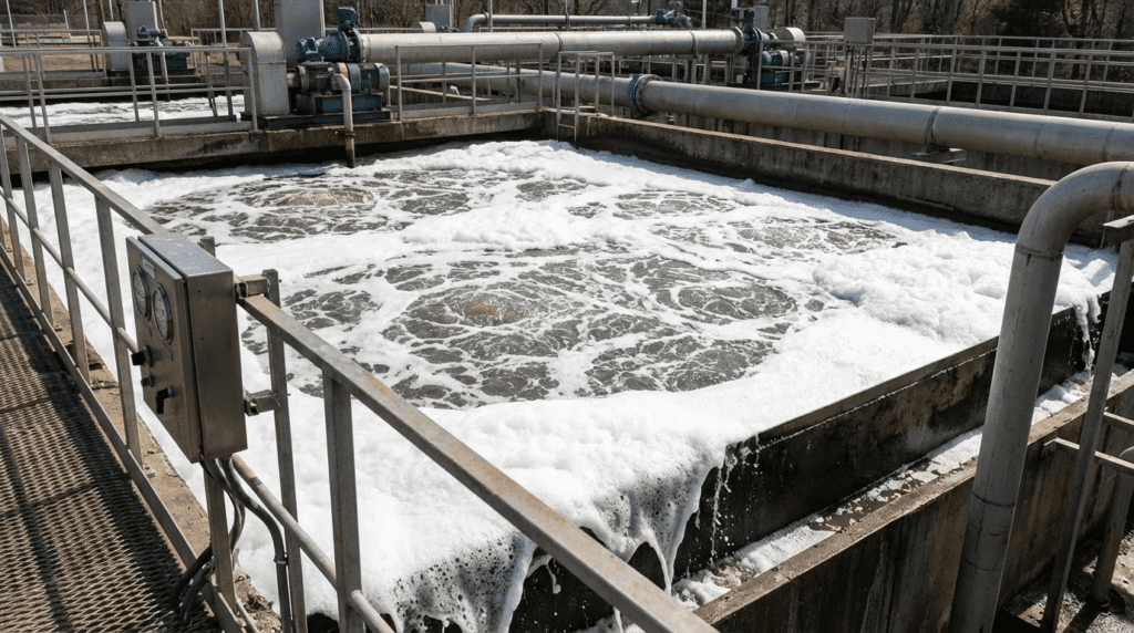
One of the most persistent, operationally disruptive, and visually alarming challenges engineers and plant operators face in wastewater treatment is uncontrolled foaming. Whether it manifests as a thick, chocolate-brown biological scum rising over the walkways of an aeration basin, or a sudden, violent expansion of gas-entrained sludge breaching the pressure relief valves of an anaerobic digester, foaming events severely compromise plant stability. A severe foaming event can lead to significant losses of mixed liquor suspended solids (MLSS), effluent permit violations, severe structural damage to digester covers, and hazardous housekeeping nightmares.
A surprising and often overlooked reality is that mechanical and chemical foaming control systems are frequently treated as afterthoughts in plant design. Most engineers focus heavily on blower sizing, aeration efficiency, and pump selection, only to scramble during plant commissioning when seasonal temperature shifts or industrial surfactant loads trigger massive foam generation. Poorly specified mitigation systems—such as undersized chemical feed skids, poorly targeted spray headers, or unreliable foam detection sensors—result in thousands of dollars wasted annually on excessive defoamer chemicals or continuous manual labor.
Foaming mitigation technologies are primarily deployed in municipal aeration basins, secondary clarifiers, and anaerobic digesters, as well as in industrial wastewater facilities treating high-strength organic loads, pulp and paper effluent, or food processing waste. Understanding the root cause—whether biological (e.g., filamentous bacteria like Nocardia or Microthrix parvicella), chemical (surfactants and detergents), or physical (gas entrapment)—is critical to selecting the correct control strategy.
This comprehensive guide will help municipal consulting engineers, utility decision-makers, and plant managers effectively select, specify, and troubleshoot mechanical and chemical foaming control systems. It provides an unbiased look at real-world performance, lifecycle costs, and the application fit of various mitigation strategies, ensuring reliable operation without over-reliance on costly consumables.
HOW TO SELECT / SPECIFY FOAMING CONTROL SYSTEMS
Mitigating foaming requires a systems-based engineering approach. Depending on the severity and root cause, engineers must specify the correct combination of surface spray infrastructure, mechanical foam classifiers/breakers, surface wasting systems, or chemical defoamer dosing skids.
Duty Conditions & Operating Envelope
The first step in specifying a foaming control system is defining the operating envelope. Foaming is rarely a static condition; it fluctuates with diurnal flow patterns, seasonal temperature inversions, and sludge age.
- Surface Area and Foam Volume: For physical suppression (spray systems), the total surface area of the aeration zone or digester must be calculated to determine nozzle count and coverage. The rate of foam generation dictates the required kinetic energy of the spray droplets.
- Operating Modes: Systems must be capable of intermittent operation triggered by sensors, continuous operation during seasonal biological blooms, and variable dosing based on foam layer thickness.
- Digester Pressures and Temperatures: In anaerobic digesters, foaming control equipment operates in an enclosed, pressurized environment. Chemical dosing lances and mechanical breakers must withstand elevated temperatures (typically 95°F–100°F for mesophilic, up to 135°F for thermophilic) and internal gas pressures up to 15-20 inches of water column (inWC).
- Chemical Viscosity Variations: Defoamer and antifoam chemistries (silicone-based, mineral oil-based, or water-based) experience massive shifts in viscosity based on ambient outdoor temperatures, severely impacting the operating envelope of chemical metering pumps.
Materials & Compatibility
Because foaming occurs at the interface of air, water, and biological mass, equipment is exposed to highly corrosive environments.
- Corrosion Resistance: Equipment installed over aeration basins is constantly exposed to moisture, aerosols, and biological H2S. Piping, spray headers, and mounting brackets should be specified as 316 Stainless Steel or UV-stabilized Schedule 80 PVC/CPVC. Digester applications require strict adherence to 316SS or specialized coatings due to continuous H2S exposure.
- Chemical Compatibility: Defoaming chemicals contain carriers and active surfactants that can aggressively degrade certain elastomers. When specifying chemical metering pumps (diaphragm or peristaltic), ensure wetted parts (e.g., EPDM, PTFE, Viton) are strictly vetted against the specific defoamer’s Safety Data Sheet (SDS). Hydrocarbon-based defoamers will rapidly destroy EPDM pump tubes.
- Abrasion Considerations: If using plant effluent or mixed liquor for spray suppression systems, nozzles must be cast from abrasion-resistant materials (e.g., hardened stainless steel, brass, or specialized polymers) to prevent the orifices from enlarging over time and degrading spray patterns.
Hydraulics & Process Performance
For chemical dosing and spray suppression, the hydraulic delivery mechanism is the most critical process performance factor.
- Spray Nozzle Hydraulics: To break foam bubbles effectively, water sprays require specific droplet sizes and impact velocities. Fine mists often bounce off thick biological foam, while solid streams punch holes without suppressing the surrounding mass. Full-cone or flat-fan nozzles operating at approximately 30-50 psi provide the optimal balance of droplet size and kinetic energy.
- Chemical Dosing Turn-Down: Defoamer metering pumps require extremely high turn-down ratios (often 1000:1 or more) via stepper-motor technology. Over-dosing defoamer not only wastes money but can severely inhibit oxygen transfer efficiency (alpha factor) in the aeration basin and blind downstream UV disinfection sleeves or ultrafiltration membranes.
- Pump NPSH and Viscosity: High-viscosity defoamers (e.g., 1000 to 5000 cP) cause significant friction losses in suction piping. Metering pumps must be positioned with minimal suction lift, utilizing flooded suction and appropriately sized (often oversized) suction piping to meet Net Positive Suction Head (NPSH) requirements and prevent pump cavitation or loss of prime.
Installation Environment & Constructability
Installing foam control infrastructure over large open basins or enclosed digester covers presents unique constructability challenges.
- Wind Drift and Spray Coverage: In open-air aeration basins, wind can easily carry water sprays away from the foam accumulation zones. Spray headers must be positioned at optimal elevations (typically 18-36 inches above the maximum water surface) and shielded where possible.
- Space Constraints and Access: Digester roofs are congested with gas piping, mixers, and safety relief valves. Installing foam suppression nozzles or mechanical foam breakers requires careful coordination to avoid structural clashes and to ensure they do not interfere with the structural integrity of floating or fixed covers.
- Winterization: Any outdoor spray headers utilizing plant service water (W3) must include automatic drain valves, heat tracing, and insulation to prevent catastrophic freezing during winter operations.
Reliability, Redundancy & Failure Modes
A failed foaming mitigation system often results in an immediate environmental spill or equipment damage.
- Common Failure Modes: The most common failure in chemical systems is pump loss of prime due to chemical off-gassing or temperature-induced viscosity spikes. For spray systems, it is nozzle clogging from biological growth or debris in the service water.
- Redundancy: Chemical feed skids should always follow an N+1 redundancy model (duty/standby). Dual-pump skids with automatic switchover valves ensure continuous operation if one pump fails.
- Nozzle Clogging Prevention: Specify self-cleaning spray nozzles or install automatic backwashing strainers (e.g., 100-micron to 200-micron) on the water supply line to prevent debris from reaching the header.
Controls & Automation Interfaces
Modern foam control must shift from continuous, manual operation to automated, demand-based deployment.
- Foam Detection Sensors: Specifying the right sensor is critical. Ultrasonic level sensors often fail because thick biological foam absorbs sound waves, causing false zero readings. Radar sensors or specialized conductive foam probes (which detect the exact interface between liquid, foam, and air) are significantly more reliable.
- Control Strategies: Implement a PID loop or simple threshold-based logic in the SCADA system. When the foam probe detects foam reaching a critical elevation, it triggers the chemical pump or spray header for a predetermined duration, followed by a stabilization wait period, to prevent over-correction.
- Monitoring: SCADA should monitor pump run times, chemical tank levels (via continuous level transducers, not just low-level floats), and water header pressure. A sudden drop in header pressure indicates a pipe break, while a spike indicates clogged nozzles.
Maintainability, Safety & Access
Systems must be designed with the operator in mind, focusing on safety around hazardous basins.
- Operator Access: Spray headers positioned over the center of an aeration basin are notoriously difficult to clean. Specify swing-arm mounts, retractable lances, or union disconnects accessible from handrailed walkways so operators do not have to lean over the basin.
- Slip Hazards: Defoamer chemicals are inherently slippery. Chemical skids must feature integral secondary containment, and dosing points should be positioned away from primary walking paths.
- Lockout/Tagout (LOTO): Ensure all automated valves and chemical pumps have accessible, clearly labeled LOTO points to isolate electrical and hydraulic energy during maintenance.
Lifecycle Cost Drivers
Engineers must evaluate the Total Cost of Ownership (TCO), balancing capital expenditures (CAPEX) with operational expenditures (OPEX).
- Chemical Dependency (OPEX): While a chemical dosing skid is relatively inexpensive to purchase (low CAPEX), reliance on proprietary defoamers over a 20-year lifecycle is immensely expensive. Defoamer costs can range from $10,000 to over $100,000 annually for large facilities.
- Energy Consumption: Running a 50 HP booster pump continuously to supply water to spray headers consumes massive amounts of electricity. Transitioning to automated, sensor-based operation can reduce energy consumption by 60-80%.
- Process Impacts: Over-dosing defoamers lowers oxygen transfer efficiency. The aeration blowers will automatically ramp up to compensate, dramatically increasing the plant’s largest electrical load. The true cost of a poorly controlled foaming system often hides in the aeration energy bill.
Whenever designing a new aeration basin or secondary clarifier, specify surface wasting capabilities (adjustable overflow weirs or scum pumps). Biologically, the bacteria that cause foaming (like Nocardia) float in the foam layer. Wasting from the bottom of the basin traps these organisms in the system. Surface wasting physically removes the biological root cause, permanently lowering chemical OPEX.
COMPARISON TABLES
The following tables provide a technical comparison of different foaming mitigation technologies and an application fit matrix to help engineers identify the most appropriate control strategy based on plant conditions.
Table 1: Foaming Control Technologies Comparison
| Technology / Approach | Primary Features | Best-Fit Applications | Limitations & Considerations | Typical Maintenance |
|---|---|---|---|---|
| Chemical Defoamer Dosing | Uses surfactants/oils to break bubble surface tension. Highly automated via skid systems. | Sudden surfactant foaming, industrial effluent, rapid deployment needs. | High OPEX. Can blind UV systems/membranes. Lowers O2 transfer efficiency. | Pump tube/diaphragm replacement, chemical inventory management, sensor cleaning. |
| Surface Water Sprays | Uses kinetic energy of water droplets to physically break foam bubbles. | Aeration basins, secondary clarifiers, temporary knockdown. | Adds hydraulic load if using potable water. Does not remove biological root cause. | Clearing clogged nozzles, servicing booster pumps, winterizing headers. |
| Mechanical Foam Breakers | Rotary impellers or classifiers that physically shear foam back into liquid form. | Anaerobic digesters, enclosed tanks, industrial fermenters. | High CAPEX. Limited radius of influence. Susceptible to ragging in raw sludge. | Bearing lubrication, seal replacement, periodic un-ragging of impellers. |
| Surface Wasting (Scum Removal) | Adjustable weirs/pumps that physically remove the floating foam layer from the process. | Biological foaming (Nocardia, Microthrix) in aeration basins. | Requires design-phase integration. Wasted scum must be handled/digested properly. | Clearing surface weirs, maintaining scum pumps and grinders. |
| Biological Selectors | Anaerobic/anoxic zones that favor floc-forming bacteria over filamentous foam formers. | Long-term municipal wastewater process stabilization. | Requires substantial plant footprint/retrofitting. Takes time to establish biology. | Mixing equipment maintenance, DO/ORP sensor calibration. |
Table 2: Application Fit Matrix
| Application Scenario | Primary Root Cause | Primary Constraint | Recommended Primary Strategy | Recommended Secondary Support |
|---|---|---|---|---|
| Aeration Basin (Winter/Spring) | Filamentous (Microthrix) | Low temperatures, long sludge age | Surface Wasting (trap & remove) | Chlorine misting / targeted chemical |
| Aeration Basin (Summer) | Filamentous (Nocardia) | High F/M ratio, grease loading | Biological Selectors / F/M adjustment | Surface Sprays for walkway safety |
| Anaerobic Digester | Gas entrapment, organic overload | Explosive environment, enclosed space | Mechanical Foam Breakers | Anti-foam chemical dosing lances |
| Industrial / Textile Effluent | Chemical surfactants / Detergents | Rapid variability in load | Automated Defoamer Skids | Surface Sprays |
| Membrane Bioreactor (MBR) | High MLSS, polymer overdosing | Membrane fouling risk from chemicals | Surface Water Sprays (Effluent reuse) | Strictly vetted, membrane-safe defoamers only |
ENGINEER & OPERATOR FIELD NOTES
Theoretical designs often clash with the messy reality of wastewater treatment. The following field notes bridge the gap between engineering specifications and operator experiences, focusing on real-world implementation, commissioning, and continuous maintenance.
Commissioning & Acceptance Testing
Proper commissioning prevents systemic failures during the first major biological bloom.
- Factory Acceptance Testing (FAT): For automated chemical skids, FAT should verify the programmable logic controller (PLC) programming, pump turn-down validation across the full 4-20mA range, and the functionality of all pressure relief and backpressure valves.
- Site Acceptance Testing (SAT): SAT for spray systems must include a physical coverage test. Fill the header, activate the booster pump, and visually verify that the spray cones overlap slightly at the water surface level. Check for blind spots near the basin corners.
- Sensor Calibration: If using conductivity or radar foam sensors, the SAT must include physical manipulation of the sensor (or simulated foam application) to ensure the SCADA system receives the trigger and accurately initiates the corresponding timers without nuisance tripping from splashing.
Common Specification Mistakes
Engineers frequently make a few highly specific errors when detailing these systems in bid documents:
- Ignoring Viscosity Curves: Specifying a standard motor-driven diaphragm pump for defoamer without requiring high-viscosity liquid ends (spring-loaded valves, larger ball checks). Thick defoamers will cause standard ball checks to float, resulting in zero chemical delivery despite the pump stroking.
- Overlooking Digester Gas Classifications: Any foam detection sensor, mechanical breaker motor, or chemical dosing instrumentation installed on an anaerobic digester must strictly comply with Class I, Division 1, Group D hazardous location requirements (NFPA 820). Standard outdoor-rated equipment will fail compliance.
- Using Potable Water Without Air Gaps: If potable city water is used for spray suppression, engineers sometimes specify simple backflow preventers instead of compliant physical air gaps. Depending on local codes, direct hard-piping over an aeration basin is a severe cross-connection violation.
Engineers and operators often use the terms interchangeably, but they serve different functions. Antifoam chemicals are designed to be dosed continuously in small amounts to prevent bubbles from forming. Defoamers are meant for shock-dosing onto existing foam to destroy it. Specifying a defoamer chemical for a continuous dosing strategy results in massive chemical waste and potential toxicity to the biomass.
O&M Burden & Strategy
Foaming mitigation systems require dedicated preventive maintenance to remain reliable.
- Routine Inspections (Weekly): Operators must physically walk the spray headers to identify clogged nozzles. Chemical skid suction lines should be visually inspected for air bubbles (cavitation or off-gassing).
- Preventive Maintenance (Quarterly/Semi-Annual): Peristaltic pump tubes dosing defoamer should be replaced every 3-6 months proactively, as hydrocarbon-based chemicals degrade rubber rapidly. Rebuild diaphragm liquid ends annually.
- Inventory Management: Defoamer chemicals have a shelf life and can separate or stratify in bulk totes. Specify low-speed drum mixers or periodic recirculation loops to keep active ingredients properly suspended.
Troubleshooting Guide
When foaming occurs, operators must first identify the type of foam to deploy the correct countermeasure.
- Thick, Chocolate-Brown, Viscous Foam: Root cause is almost always biological (Nocardia). It traps air and floats. Quick Fix: Surface water sprays to clear walkways. Permanent Solution: Surface wasting, reducing sludge age (SRT), and identifying grease/fat inputs in the headworks.
- White, Billowing, Light Foam: Often indicates a young sludge age, startup conditions, or nutrient deficiency (F/M imbalance). Quick Fix: Light defoamer dosing. Permanent Solution: Allow MLSS to build up; seed with mature sludge if necessary.
- White, Bubbly, Sudsy Foam: Indicates chemical surfactants, detergents, or industrial spills. Quick Fix: Automated defoamer shock dosing. Permanent Solution: Source control via industrial pretreatment programs.
- Digester Rapid Foaming: Usually caused by an organic shock load, sudden temperature spike, or poor mixing leading to localized methanogenic failure. Quick Fix: Reduce or halt feed, apply anti-foam chemicals directly to the digester surface. Permanent Solution: Stabilize heating systems and equalize feed rates.
DESIGN DETAILS / CALCULATIONS
Proper sizing of chemical dosing and spray suppression systems relies on fundamental fluid mechanics and geometric principles.
Sizing Logic & Methodology
1. Spray System Sizing:
To determine the required flow for a surface spray system, engineers must calculate the optimal nozzle spacing and flow rate. Assume a standard flat-fan nozzle provides an 80-degree spray angle.
- Step 1: Calculate Coverage Width. The spray width ($W$) at the water surface is calculated using trigonometry: $W = 2 times H times tan(theta/2)$, where $H$ is the height above the surface and $theta$ is the spray angle. For a nozzle 24 inches high with an 80° angle, coverage width is approx. 40 inches.
- Step 2: Determine Overlap. To prevent blind spots, nozzles should be spaced to provide 20-30% overlap. Therefore, space nozzles every 28-32 inches along the header.
- Step 3: Total Flow Rate. Multiply the number of nozzles by the manufacturer’s rated flow at the design pressure (e.g., 2.0 GPM at 40 PSI). A 40-foot header requiring 15 nozzles will require 30 GPM of water supply.
2. Defoamer Chemical Dosing Sizing:
Sizing a defoamer pump requires translating laboratory jar testing (mg/L) into a field-scale gallons-per-day (GPD) rate.
- Rule of Thumb: Typical biological foam defoamer dosing ranges from 0.5 to 3.0 mg/L (ppm) based on the influent flow rate of the basin, though severe industrial foaming may require 5.0 to 10.0 mg/L.
- Calculation: Dosing Rate (GPD) = [Flow (MGD) × Dose (mg/L) × 8.34] / Chemical Specific Gravity.
- If a plant processes 5 MGD and requires a 2 mg/L dose of a defoamer with a specific gravity of 0.95: (5 × 2 × 8.34) / 0.95 = 87.8 lbs/day, or roughly 11 gallons per day. The metering pump should be sized with a capacity of roughly 24 GPD to ensure it operates in the middle of its curve, allowing for peak dosing capacity during severe events.
Specification Checklist
When drafting specifications for foaming mitigation packages, ensure the following are explicitly detailed:
- Pump Turn-down Ratio: Minimum 1000:1 for chemical skids.
- Viscosity Rating: Specify that pumps, piping, and calibration columns must accommodate fluids up to 3,000 cP at minimum ambient temperature.
- Sensor Technology: Explicitly ban standard ultrasonic sensors; require phase-detection or conductive foam sensors for primary automation.
- Materials of Construction: Wetted parts must include chemically resistant elastomers (PTFE, PVDF, specialized Viton). 316SS or FRP for basin mounts.
- Redundancy: Dual duty/standby configurations with automatic failover based on flow verification (not just motor run status).
Standards & Compliance
Engineers must design these systems in compliance with industry safety and quality standards:
- NFPA 820: Standard for Fire Protection in Wastewater Treatment and Collection Facilities. Dictates the explosion-proof ratings (Class, Division, Group) for any electrical equipment mounted near anaerobic digesters or enclosed headworks.
- Ten States Standards: Provides guidelines on cross-connection control, ensuring service water lines used for spray headers feature appropriate air gaps or reduced-pressure zone (RPZ) backflow preventers.
- AWWA / ANSI: Standards for PVC and stainless steel pipe scheduling and pressure ratings.
- UL 508A: Industrial Control Panels standard; essential for the specification of automated chemical skid control panels.
FAQ SECTION
What is the primary cause of biological foaming in aeration basins?
Biological foaming is primarily caused by hydrophobic, filamentous bacteria, most notably Nocardia species and Microthrix parvicella. These organisms thrive in environments with high fats, oils, and grease (FOG), long sludge retention times (SRT), or specific seasonal temperature changes. Their cell walls repel water and trap aeration bubbles, creating a stable, dense, brown scum that floats to the surface.
How do you select the right defoaming chemical for wastewater?
Selecting a defoamer requires jar testing using actual mixed liquor from the plant. Engineers must test silicone-based, mineral oil-based, and ester-based chemicals to determine which breaks the foam fastest without negatively impacting the biomass. Crucially, the chemical must be evaluated for its impact on downstream processes; silicone-based defoamers can severely foul ultrafiltration membranes and blind UV disinfection quartz sleeves.
What’s the difference between surface wasting and chemical control for foaming?
Surface wasting is a mechanical/biological mitigation strategy that physically removes the foam layer (which contains the foam-causing bacteria) out of the system via adjustable weirs or scum pumps. Chemical control uses surfactants to simply collapse the bubbles. Surface wasting is a permanent, biological fix that removes the root cause, whereas chemical control is a temporary, symptomatic treatment with high ongoing OPEX. [[See Surface Wasting vs. Chemical Control in Section 2]].
How much does a chemical defoamer dosing skid cost?
For municipal applications, a standard dual-pump (duty/standby) chemical dosing skid with a local control panel, flow verification, and basic SCADA outputs typically costs between $15,000 and $35,000 (CAPEX). However, the chemical itself (OPEX) can easily cost $20,000 to $80,000 annually depending on flow rate, foam severity, and plant size, making lifecycle cost analysis essential.
Why do ultrasonic sensors fail when measuring foam levels?
Ultrasonic sensors rely on sound waves bouncing off a dense surface and returning to the transducer to calculate distance. Thick biological foam is highly porous and acoustically absorbent. Instead of reflecting the sound wave, the foam absorbs it, causing the sensor to either output a false “zero level” reading or fluctuate wildly. Conductive probes or radar technologies are standard best practices for detecting foam interfaces.
How do you prevent anaerobic digester foaming?
Digester foaming is usually mitigated by maintaining strict operational stability. Prevent rapid temperature fluctuations, avoid organic shock loading (e.g., dumping a massive batch of high-strength FOG), and maintain continuous, uniform mixing. From an equipment standpoint, installing mechanical foam breakers inside the digester dome and having emergency anti-foam dosing lines readily available are critical design safeguards.
How often should spray nozzles over an aeration basin be maintained?
Spray nozzles should be visually inspected weekly for blockages. If the system utilizes plant effluent (W3 water) rather than potable water, nozzles may require manual cleaning or descaling every 1 to 3 months depending on suspended solids and biological growth. Installing automated backwashing strainers upstream of the spray header significantly reduces this maintenance burden. [[See O&M Burden & Strategy]].
CONCLUSION
KEY TAKEAWAYS FOR ENGINEERS
- Identify the Root Cause: Chemical dosing will not permanently solve a biological foaming issue. Address sludge age (SRT), F/M ratios, and FOG loading first.
- Design for Surface Wasting: Always incorporate surface overflow weirs or scum pumps in aeration basin designs to physically trap and remove foam-causing filaments.
- Sensor Accuracy is Paramount: Never specify ultrasonic level sensors for foam detection. Use conductive phase-detection probes or radar to trigger automated systems reliably.
- Beware the OPEX Trap: Defoamer chemical costs will dwarf the initial CAPEX of a skid within the first 1-2 years. Design systems for intermittent, automated dosing rather than continuous feed.
- Protect Downstream Assets: Strictly vet defoamer chemistries. Avoid heavy silicone-based defoamers if the plant utilizes membrane bioreactors (MBR) or UV disinfection.
- Digester Safety: All foaming mitigation equipment installed on or near anaerobic digesters must strictly adhere to NFPA 820 Class I, Div 1 hazardous location standards.
Managing and mitigating foaming in wastewater treatment requires a comprehensive understanding of plant biology, chemistry, and fluid dynamics. For consulting and utility engineers, treating foam control as an integrated part of the process design—rather than a reactive afterthought—is critical for protecting plant infrastructure and ensuring permit compliance.
Engineers must balance the immediate relief provided by chemical defoamers and mechanical sprays with the long-term, stable results achieved through process optimizations like surface wasting and biological selectors. When specifying equipment, strict attention must be paid to the operating envelope, particularly the high turn-down requirements of viscous chemical metering pumps and the physical constraints of open-air or highly corrosive environments.
By shifting from manual, continuous chemical dosing to automated, sensor-driven deployment, utilities can dramatically reduce their operational expenditures, protect oxygen transfer efficiency, and alleviate the intense maintenance burden on operators. Ultimately, a properly engineered foaming control system acts as a reliable safeguard, intervening precisely when needed to stabilize the plant without masking underlying biological imbalances.