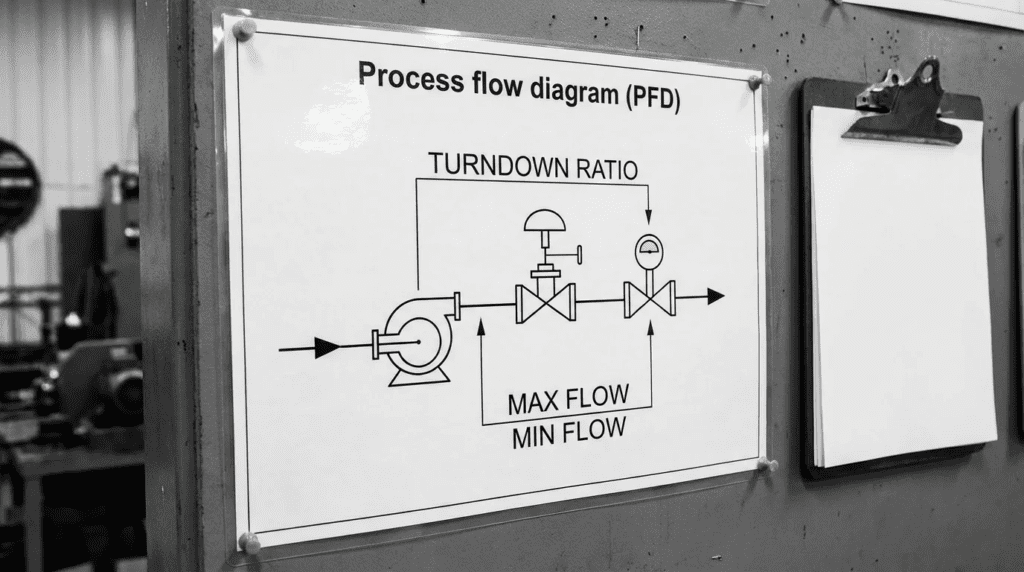
Turndown
1) INTRODUCTION
One of the most persistent and costly errors in municipal water and wastewater engineering is designing for a 20-year future peak flow while failing to account for Year 1 minimums. This clash between design horizons and current realities makes understanding turndown a critical, yet frequently mishandled, engineering competency. When consulting engineers specify equipment strictly based on maximum future duty points, utilities are forced to operate heavily oversized pumps, blowers, and valves at extreme turndown conditions. This operational mismatch leads to premature mechanical seal failures, destructive blower surge, severe valve cavitation, and skyrocketing energy consumption.
Turndown—defined as the ratio of an equipment’s maximum capacity to its minimum controllable and safe operating capacity (e.g., a 4:1 turndown ratio)—dictates the operational flexibility of the entire treatment process. In municipal and industrial water and wastewater systems, turndown applies heavily to centrifugal pumping systems (both clean water and solids-handling), aeration blowers, control valves, chemical dosing systems, and UV disinfection arrays.
Typical operating environments, such as diurnal wastewater flow patterns or seasonal industrial discharge fluctuations, require equipment to handle massive duty swings. For instance, an influent pump station may see 10 MGD during a wet-weather event but only 1.5 MGD during dry-weather night flows. If the pumping system lacks the necessary turndown capability to safely handle that 1.5 MGD without dead-heading or vibrating excessively, the utility faces severe maintenance burdens.
Properly specifying turndown limits prevents the destructive consequences of operating outside an asset’s Preferred Operating Region (POR) or surge boundaries. This article provides design engineers, utility managers, and operators with a rigorous, specification-safe framework for analyzing, specifying, and managing equipment turndown across mechanical, hydraulic, and control disciplines.
2) HOW TO SELECT / SPECIFY
Selecting equipment with adequate turndown requires an integrated approach that balances hydraulics, materials science, automation, and lifecycle economics. The following criteria must be rigorously evaluated during the design and submittal review phases.
Duty Conditions & Operating Envelope
The foundation of specifying turndown is accurately defining the operating envelope. Engineers must clearly delineate the maximum (peak hourly), average (daily), and minimum (diurnal low) flow rates, alongside corresponding system pressures or heads.
- Flow and Head Variations: Centrifugal equipment turndown is intimately tied to the system curve. As variable frequency drives (VFDs) reduce speed to turn down flow, the equipment must still overcome static head. If static head is high relative to friction head, turndown capability is severely truncated.
- Operating Modes: Determine if the equipment will run continuously at high turndown or if intermittent “fill-and-draw” batching is acceptable. Continuous low-flow operation requires highly robust turndown capabilities, whereas intermittent operation can utilize simple on/off controls, bypassing the need for deep turndown entirely.
- Future Capacity Phasing: Instead of installing a single unit to handle Year 20 peak flows—resulting in massive Year 1 turndown challenges—engineers should consider multi-unit installations (e.g., “jockey” or “trim” pumps/blowers alongside larger duty units).
Materials & Compatibility
Operating equipment at its maximum turndown limit frequently alters the physical dynamics of the fluid or gas being handled, necessitating specific material considerations.
- Heat Dissipation: At extreme turndown (low flow), the fluid passing through a pump or valve may not carry away the heat generated by friction or motor inefficiency. In chemical dosing or high-pressure pumping, this can lead to fluid flashing. Materials must be specified to withstand elevated localized temperatures.
- Abrasion and Cavitation Damage: Operating valves at high turndown (mostly closed) creates high-velocity fluid jets. If abrasive grit is present, this accelerates trim erosion. Furthermore, high pressure drops at low flows often induce cavitation, necessitating hardened materials like 316SS, Stellite overlays, or specialized anti-cavitation trims.
- Shaft Deflection and Fatigue: Operating a centrifugal pump at high turndown (far left of the Best Efficiency Point – BEP) drastically increases radial thrust. This bends the shaft, requiring heavy-duty shaft materials (e.g., Duplex stainless steels or high-tensile alloys) to prevent fatigue failure and seal face separation.
Hydraulics & Process Performance
The hydraulic constraints of turndown are absolute; they are governed by physics and cannot be bypassed solely by control system programming.
- Minimum Continuous Safe Flow (MCSF): For pumps, MCSF is the absolute turndown limit dictated by the manufacturer to prevent damaging suction/discharge recirculation and excessive vibration. Operating below MCSF voids warranties and destroys equipment.
- Blower Surge Limits: Dynamic blowers (centrifugal and turbo) possess a surge line. If flow is turned down below this aerodynamic limit (typically 40-50% of design flow), the air reverses direction violently. High turndown aeration applications often require positive displacement (PD) blowers or multiple small turbo blowers rather than one large unit.
- Control Valve Authority: A valve’s inherent turndown ratio (e.g., 50:1 for a globe valve) is theoretical. Its installed turndown ratio is always lower due to system friction eating up the valve’s pressure drop authority. Engineers must plot installed characteristic curves to verify the valve actually retains control at the specified low flows.
Installation Environment & Constructability
The physical installation environment interacts with turndown performance, particularly concerning flow conditioning and structural resonance.
- Piping Geometry: Equipment operating at maximum turndown is highly sensitive to turbulent or asymmetrical inlet flow. High turndown control valves and pumps require strict adherence to straight-run piping requirements (e.g., 5 to 10 pipe diameters upstream) to prevent aggravated vibration and instability.
- Structural Resonance: VFDs operating at low speeds (high turndown) may hit the natural resonant frequency of the baseplate, piping system, or elevated concrete slab. Structural mass and stiffness must be engineered to avoid sympathetic vibration across the entire turndown speed range.
- Motor Cooling Constraints: Standard TEFC (Totally Enclosed Fan Cooled) motors lose cooling capacity when VFDs turn their speed down, as the shaft-driven fan slows. For extreme turndown applications, continuous duty motors with separately powered cooling fans (TEBC) or specifically rated inverter-duty motors (NEMA MG-1 Part 31) are required.
Reliability, Redundancy & Failure Modes
Deep turndown operation shifts the primary failure modes of mechanical equipment.
- MTBF Reductions: Operating continuously at the edge of the allowable turndown envelope can reduce the Mean Time Between Failures (MTBF) for bearings and mechanical seals by 50% or more due to continuous low-level vibration and unbalanced hydraulic loads.
- Redundancy Strategies: Instead of relying on a single large unit with a theoretical 10:1 turndown, modern plant reliability dictates an N+1 or N+2 configuration of smaller units operating nearer to their BEP, staging on and off to meet demand.
- Critical Spares: If wide turndown operation is unavoidable, plants must increase inventory for wear rings, mechanical seals, and bearings, as the consumption rate for these components will accelerate.
A common specification mistake is assuming that adding a Variable Frequency Drive (VFD) grants a piece of equipment infinite turndown. VFDs cannot bypass hydraulic laws. In systems with high static head, reducing pump speed by just 15-20% may cause the pump’s head curve to fall below the system static head, resulting in zero flow (dead-heading) despite the motor still spinning. Always plot the turndown speed curves against the actual system curve.
Controls & Automation Interfaces
Implementing effective turndown requires precise, responsive automation.
- PID Loop Tuning at Low Flows: System dynamics change drastically at high turndown. A PID loop tuned for peak flow will often “hunt” or oscillate wildly at low flows. Advanced control strategies may require gain scheduling, where different PID parameters are utilized depending on the turndown state.
- Deadbands and Minimum Speeds: SCADA systems must be programmed with hard-coded minimum speed limits (e.g., 35 Hz) derived from the equipment’s MCSF or surge limit, preventing operators from manually turning down equipment into destructive operational zones.
- Instrumentation Limits: The turndown ratio of the primary measurement instrument (e.g., a magnetic flow meter or dissolved oxygen sensor) must exceed the turndown ratio of the mechanical equipment. You cannot control what you cannot accurately measure.
Maintainability, Safety & Access
Equipment that operates under heavy turndown conditions requires distinct maintenance protocols.
- Vibration Monitoring Access: Because high turndown operation increases the risk of vibration-induced damage, structural access for continuous condition monitoring (e.g., permanently mounted accelerometers) or routine handheld vibration checks is mandatory.
- Thermal Safety: Pumps operating near shut-off head (maximum turndown) can boil the internal fluid within minutes if a discharge valve fails closed. Casing temperature sensors and high-temperature shut-off interlocks should be specified for these scenarios to protect operator safety.
Lifecycle Cost Drivers
The Total Cost of Ownership (TCO) is heavily influenced by how turndown is achieved and managed.
- Efficiency Collapse: As centrifugal pumps and blowers are turned down away from their BEP, efficiency plummets. A 200 HP pump running at 30% capacity might operate at 40% efficiency, wasting massive amounts of energy.
- CAPEX vs. OPEX Tradeoffs: Utilizing multiple smaller units (a “core/trim” setup) increases initial CAPEX (more concrete, more piping, more electrical drops) but drastically lowers OPEX by keeping all running units near peak efficiency and extending equipment lifespan.
- VFD Efficiency and Harmonics: VFD efficiency itself drops at low speeds. Additionally, operating at high turndown may require harmonic mitigation (line reactors or active front ends) depending on utility power quality requirements, adding to the installation cost.
3) COMPARISON TABLES
The following tables provide an objective framework for engineers to evaluate how different technologies and strategies handle turndown. Table 1 outlines the inherent turndown capabilities and limitations of common water and wastewater equipment. Table 2 provides a decision matrix for selecting the most appropriate system-level turndown strategy based on application constraints.
| Technology / Type | Typical Turndown Ratio | Primary Mechanism for Turndown | Limitations at High Turndown | Typical Maintenance Impact |
|---|---|---|---|---|
| Centrifugal Pumps (Radial Flow) | 2:1 to 4:1 (Application Dependent) | Variable Frequency Drive (VFD), Throttling Valve | Limited by Minimum Continuous Safe Flow (MCSF). Static head limits speed reduction. Radial thrust increases. | Accelerated wear on mechanical seals, bearings, and wear rings due to vibration and shaft deflection. |
| Positive Displacement Pumps (Rotary Lobe / PC) | 10:1 to 15:1 | VFD (Speed directly correlates to flow) | Motor cooling at low RPMs. Slip increases slightly at high pressures and low speeds. | Minimal hydraulic impact, but requires inverter-duty motors with separate cooling fans for continuous low-speed running. |
| Turbo Blowers (Centrifugal) | 2:1 to 2.5:1 (approx. 40-50% minimum) | VFD, Inlet Guide Vanes (IGVs), Variable Diffuser Vanes (VDVs) | Aerodynamic Surge. Operating below the surge line causes catastrophic flow reversal. | Surge events can destroy air foil bearings or mechanical bearings instantly. Strict control system required. |
| Positive Displacement Blowers (Roots-style) | 3:1 to 4:1 | VFD | Limited by motor cooling and increased slip at high pressures. Noise profiles change. | Oil temperature monitoring critical at low speeds; poor cooling can degrade lubricants faster. |
| Control Valves (Butterfly – High Performance) | 10:1 to 15:1 (Inherent) | Actuator positioning (Disk rotation) | Poor control near closed positions (<20 degrees). High risk of cavitation and noise at high pressure drops. | Trim erosion, seat wear, and actuator linkage wear from “hunting” to maintain low flows. |
| Control Valves (Globe / V-Port Ball) | 50:1 to 100:1 (Inherent) | Actuator positioning (Plug/Ball rotation) | Higher pressure drop even when fully open. Larger footprint, higher CAPEX. | Generally excellent wear profile, though anti-cavitation trims may clog in raw wastewater applications. |
| Application Scenario | Best-Fit Turndown Strategy | System Constraints to Check | Lifecycle / Cost Impact | Operator Burden |
|---|---|---|---|---|
| High Static Head Pumping (e.g., Force Mains with large elevation changes) | Multiple identical pumps operating in parallel (Staging ON/OFF) | VFDs are ineffective here; a small speed drop hits dead-head. Ensure check valves are robust. | Medium CAPEX (multiple pumps). Low OPEX (always running near BEP). | Low. Standard lead/lag/standby controls. Easy to understand. |
| High Friction Head Pumping (e.g., Long, flat pipelines) | Single or dual large pumps with VFDs | Check MCSF limits and motor cooling limits at lowest expected flow. | Low CAPEX. Medium OPEX (efficiency drops at low speeds, but friction losses also drop). | Low. Requires proper PID tuning for the VFD response. |
| Extreme Diurnal Swings (e.g., Aeration demand dropping 80% at night) | “Core/Trim” Configuration (Large base-load units + small PD or turbo trim units) | Ensure automated valving and headers can isolate units. SCADA must manage complex staging. | High CAPEX (mixed sizes, more piping). Very Low OPEX (maximum system efficiency). | High. SCADA programming must be seamless to prevent operator frustration during transitions. |
| Precise Chemical Dosing at Micro-Flows (e.g., Coagulant dosing in winter) | Peristaltic or smart stepper-motor diaphragm pumps | Avoid using oversized standard motor-driven diaphragms on VFDs. | Low CAPEX. Low OPEX. | Low. Tubing/diaphragm changes are routine and predictable. |
| High-Pressure Drop Flow Control (e.g., Pump discharge throttling to prevent run-out) | V-Port Ball Valve or Cavitation-Resistant Globe Valve | Avoid standard butterfly valves which will cavitate and fail quickly. | High CAPEX (specialty valves). Low OPEX (long life). | Low. Robust valves require little intervention if sized correctly. |
4) ENGINEER & OPERATOR FIELD NOTES
Theoretical turndown calculations in the design office often face harsh realities in the field. The following field notes provide practical guidance for ensuring specified turndown parameters perform reliably in actual operation.
Commissioning & Acceptance Testing
Verifying turndown capabilities is one of the most critical aspects of commissioning, yet it is frequently glossed over in favor of simply proving maximum capacity.
- FAT/SAT Critical Checkpoints: During Factory Acceptance Testing (FAT) and Site Acceptance Testing (SAT), equipment must be intentionally operated at its minimum specified turndown point for a sustained duration (e.g., 1 to 4 hours) to verify thermal stability and vibration limits.
- Surge Testing (Blowers): For aeration blowers, a supervised “surge test” must be conducted during SAT. The blow-off valve is slowly closed, and the blower is turned down until incipient surge is detected. The SCADA surge-protection line must then be programmed safely above this mapped boundary (typically a 5-10% safety margin).
- Vibration Baselines: Vibration mapping should be performed across the entire speed/turndown range. It is common to find a narrow resonance band at a specific intermediate speed. If this cannot be tuned out mechanically, the VFD must be programmed to “skip” this frequency band.
Common Specification Mistakes
Engineers often generate operational headaches by committing several classic specification errors regarding turndown.
- The “Safety Factor” Stacking Error: An engineer adds a 15% safety factor to the flow, and another 15% safety factor to the head. The resulting pump is massively oversized. During Year 1 low-flow conditions, the pump must turn down so far that it operates continuously in its allowable operating region (AOR) rather than its preferred operating region (POR), leading to rapid degradation.
- Ambiguous Turndown Requirements: Specifying “Pump shall be capable of 4:1 turndown” is ambiguous. Does this mean 4:1 flow turndown, or 4:1 speed turndown? Does it account for system static head? Specifications must state: “Equipment shall operate continuously without exceeding vibration limits of [X] in/sec RMS at a minimum flow rate of [Y] GPM.”
- Neglecting VFD Cable Lengths: Running equipment at high turndown via VFDs creates reflected wave phenomena (dv/dt) which degrades motor insulation. If the VFD is located far from the motor (e.g., >100 feet), specifications must require load reactors or specialized dv/dt filters, which are often missed in design.
Specifying a standard linear or quick-opening valve for a system requiring wide turndown is a recipe for control failure. At low flows, the valve will only be slightly open. A tiny change in position will cause a massive change in flow, causing the control loop to oscillate endlessly. For wide turndown applications, always specify an Equal Percentage trim characteristic, which provides precise control at low flow rates.
O&M Burden & Strategy
Plant operators must adjust maintenance strategies for equipment subjected to continuous high turndown.
- Preventive Maintenance Adjustments: Equipment running constantly at the edge of its turndown limits should have its preventive maintenance (PM) intervals shortened by 30-50%. Bearing grease intervals and oil change frequencies must be accelerated to counter the increased mechanical stress.
- Predictive Maintenance (PdM): High turndown applications are prime candidates for permanent vibration and temperature sensors. By trending vibration data against VFD speed in a SCADA historian, operators can identify exact speeds where bearing wear is accelerating.
- Bypass/Recirculation Line Inspections: If turndown is achieved via a minimum flow bypass line (common in boiler feed or high-pressure applications), the bypass valve and orifice plates will experience extreme velocities. These must be inspected annually for cavitation erosion and wire-drawing.
Troubleshooting Guide
When turndown limits are breached, specific symptoms manifest in the field.
- Symptom: Gravel-like noise in pump at low flows.
Root Cause: Suction or discharge recirculation. The flow is too low for the impeller geometry, causing fluid to separate from the vanes and create localized cavitation-like vortices.
Fix: Increase minimum flow limit on VFD, open a bypass line, or trim the impeller if peak flows are never realized. - Symptom: Valve “hunting” (actuator constantly moving back and forth).
Root Cause: Valve is oversized and operating in the bottom 10% of its stroke where it lacks control authority, OR the PID loop is tuned too aggressively for low-flow dynamics.
Fix: Retune PID loop (lower proportional gain, increase integral time). If mechanical, install a reduced-port trim inside the valve body. - Symptom: Blower makes a rhythmic “whooshing” or “coughing” sound, accompanied by pipe shaking.
Root Cause: Blower is operating below its surge limit; aerodynamic stall is causing flow to reverse back into the blower.
Fix: Immediate intervention required. Open blow-off valve, increase blower speed, or adjust inlet guide vanes (IGVs). Adjust SCADA limits to prevent reaching this speed/turndown ratio again.
5) DESIGN DETAILS / CALCULATIONS
Executing a design with proper turndown capability requires mathematical validation. Engineers must prove that the selected equipment can satisfy both ends of the duty spectrum.
Sizing Logic & Methodology
The methodology for analyzing centrifugal pump turndown on a VFD requires mapping the pump curves against the system curve using the Affinity Laws, while recognizing their limitations.
- Establish the System Curve: Plot the system curve based on static head (elevation + minimum pressure requirements) and dynamic friction head. Critical Rule: Static head does not change with flow.
- Determine Turndown Ratio Requirement:
Ratio = Q_max / Q_min
(e.g., Peak flow 5000 GPM / Minimum flow 1000 GPM = 5:1 required turndown). - Apply Affinity Laws (with caution): Use the Affinity Laws (Q₁/Q₂ = N₁/N₂, H₁/H₂ = (N₁/N₂)²) to plot the pump curve at reduced speeds (e.g., 50 Hz, 40 Hz, 35 Hz).
- Identify the Intersection Point: Find where the reduced-speed pump curve intersects the system curve at Q_min.
- Verify Against Constraints:
- Does this intersection occur to the right of the manufacturer’s MCSF line?
- Is the motor speed above the minimum cooling threshold (typically 20-30 Hz for standard motors)?
- Is the intersection point inside the HI-defined Preferred Operating Region (POR)?
If the answer to any of the verification questions is “No,” a single pump on a VFD cannot handle the turndown. The design must pivot to multiple smaller pumps or a different pumping technology.
Specification Checklist
To protect the design intent, the following clauses should be included in equipment specifications:
- MCSF Documentation: “Manufacturer shall submit minimum continuous safe flow (MCSF) curves. Equipment shall not be subjected to operation below MCSF under any specified operating condition.”
- Vibration Thresholds: “Equipment vibration shall not exceed Hydraulic Institute / ANSI standards across the entire specified turndown range from [X] Hz to 60 Hz.”
- Control Valve Authority: “Valve supplier shall provide installed characteristic curves demonstrating a minimum valve authority of 0.3 (30%) at the specified minimum flow rate.”
- Blower Surge Mapping: “Aeration blower control panel shall include automated surge mapping and prevention logic, utilizing differential pressure and motor current to detect and avoid surge lines regardless of ambient air temperature and density.”
Standards & Compliance
Several industry standards dictate acceptable limits for turndown operation:
- Hydraulic Institute (HI) 9.6.3 – Preferred Operating Region (POR): HI standardizes that pumps should generally operate between 70% and 120% of their Best Efficiency Point (BEP) flow. Operating continuously outside the POR (in the Allowable Operating Region – AOR) significantly reduces seal and bearing life. Turndown designs must account for POR limits.
- ANSI/ISA-75.01.01 (Control Valves): Flow equations for sizing control valves to ensure proper pressure drop and sizing limits to avoid cavitation at deep turndown.
- NEMA MG-1 Part 31: Defines the performance standards for definite-purpose inverter-fed polyphase motors, detailing cooling requirements and insulation limits essential for motors running at high turndown (low RPM).
6) FAQ SECTION
What is a turndown ratio in water and wastewater equipment?
A turndown ratio is the mathematical ratio between an equipment’s maximum operating capacity and its minimum controllable, safe operating capacity. For example, a pump that can safely deliver a maximum of 1000 GPM and a minimum of 250 GPM has a 4:1 turndown ratio. Operating below the minimum limit generally results in mechanical damage, inefficiency, or loss of process control.
Why do centrifugal pumps have limited turndown on VFDs?
Centrifugal pumps are limited by two main factors. First, system static head: as speed decreases, the pump’s ability to generate head drops exponentially. If speed drops too low, the pump cannot overcome static head and flow stops entirely (dead-heading). Second, internal recirculation: at low flows, fluid separates from the impeller vanes, causing damaging recirculation, vibration, and heat buildup. See the [[Hydraulics & Process Performance]] section for details on MCSF.
What is the difference between inherent and installed valve turndown?
Inherent turndown is the theoretical ratio of maximum to minimum controllable flow of a valve tested in a lab with a constant pressure drop. Installed turndown is the actual ratio achieved in the field, where system piping friction causes the pressure drop across the valve to change as the valve opens and closes. Installed turndown is always significantly lower than inherent turndown.
How does high turndown affect equipment lifespan?
Operating equipment continuously at maximum turndown limits dramatically reduces its lifespan. For pumps, operating far from the Best Efficiency Point (BEP) increases radial thrust, bending the shaft and destroying bearings and mechanical seals—often reducing MTBF by 50% or more. For valves, operating mostly closed creates high-velocity fluid jets that erode the valve trim.
What is blower surge and how does it relate to turndown?
Blower surge is an aerodynamic instability that occurs when a centrifugal or turbo blower is turned down past its minimum capacity limit (the surge line). The blower can no longer generate enough pressure to overcome system resistance, causing the air to rapidly reverse direction. This violent pulsing can instantly destroy the blower’s bearings. Blower turndown is strictly limited by this surge line.
Can a VFD provide infinite turndown capability?
No. A highly prevalent specification error is assuming VFDs provide infinite turndown. While a VFD can electrically turn a motor down to 1 Hz, the mechanical and hydraulic realities of the attached equipment—such as pump dead-heading, blower surge, loss of motor cooling, and loss of lubrication—dictate a much narrower safe operating range. Refer to the [[Sizing Logic & Methodology]] for proper evaluation.
What is the best strategy for handling extreme flow variations?
For systems with massive diurnal or seasonal swings, the most reliable and lifecycle-efficient strategy is utilizing a multiple-unit configuration. Instead of forcing one large unit to turn down 10:1, engineers should specify “core/trim” setups—for instance, a large base-load unit paired with a smaller jockey pump or trim blower. This keeps all active equipment operating near its optimal efficiency point. See [[Table 2: System-Level Turndown Strategy Selection Matrix]].
7) CONCLUSION
- Physics Trumps Controls: VFDs and automation cannot bypass physical hydraulic limits. Static head, MCSF, and surge lines dictate absolute turndown boundaries.
- Beware the POR vs. AOR Gap: Operating continuously outside the Preferred Operating Region (POR) and in the extreme Allowable Operating Region (AOR) will drastically reduce equipment MTBF.
- Valve Installed Characteristic is Crucial: Never rely on a valve’s inherent turndown. Always calculate installed control authority to ensure precision at minimum diurnal flows.
- Multiple Units > Single Oversized Unit: Resolving Year 1 vs Year 20 capacity gaps is best achieved through staging multiple smaller units (core/trim) rather than forcing wide turndown on a single large asset.
- Verify During FAT/SAT: Always test equipment at its absolute minimum flow/speed limit during acceptance testing to verify vibration and thermal stability.
Mastering equipment turndown is a hallmark of sophisticated water and wastewater engineering. The tendency to over-specify equipment capacity to satisfy distant, speculative future peaks creates an immediate, decades-long operational burden for the utility in the form of extreme turndown requirements. By understanding the thermodynamic, hydraulic, and aerodynamic limitations of pumps, blowers, and valves, consulting engineers and plant directors can bridge the gap between process requirements and mechanical realities.
Proper turndown design requires a holistic evaluation of the system curve, diurnal flow profiles, lifecycle energy costs, and maintenance burdens. Rather than demanding impossible 10:1 turndown ratios from dynamic equipment, engineers must deploy intelligent system architectures—such as trim units, specialized valve trims, and rigorous VFD control logic. When specialized applications demand operating near the extreme boundaries of an equipment’s capability, involving the manufacturer early to establish verifiable Minimum Continuous Safe Flows (MCSF) and surge boundaries is paramount. Ultimately, aligning the equipment’s preferred operating region with the plant’s actual, real-world daily duty cycle ensures long-term reliability, minimal operator intervention, and optimized total cost of ownership.