Top Aeration Blower Manufacturers for Water & Wastewater
Introduction
In municipal and industrial biological treatment facilities, aeration systems routinely account for 50% to 60% of total plant energy consumption. A poorly specified blower package directly translates to hundreds of thousands of dollars in wasted electrical expenditures over a standard 20-year lifecycle. Despite this immense operational expense, the evaluation and selection of the Top Aeration Blower Manufacturers for Water & Wastewater remains a frequent source of friction, miscalculation, and ambiguous specifications during the design phase.
Biological nutrient removal (BNR), conventional activated sludge (CAS), membrane bioreactors (MBR), and sequencing batch reactors (SBR) rely on a continuous, highly variable supply of low-pressure air. Blower systems must deliver necessary standard cubic feet per minute (SCFM) while overcoming dynamic hydrostatic heads, diffuser backpressures, and friction losses. They must also rapidly adapt to diurnal loading swings and seasonal temperature variations without entering aerodynamic surge or inefficient bypass modes.
This technical article provides consulting engineers, utility directors, and maintenance superintendents with an unbiased framework for evaluating blower technologies and Original Equipment Manufacturers (OEMs). By moving beyond nominal brochure claims, this guide focuses on real-world wire-to-air efficiency, lifecycle costs, ASME PTC 13 compliance, control integration, and strict application fit to ensure robust, specification-safe procurement.
Core Technical Content: Technology & Application Requirements
Operating Conditions & Duty Requirements
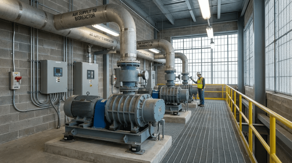
Aeration blowers in wastewater treatment generally operate in a low-pressure, high-volume regime. Typical discharge pressures range from 6 to 12 psig (40 to 80 kPa) depending on the basin’s static water depth (usually 15 to 25 feet) and the condition of the fine-bubble diffusers. Airflow requirements can span from less than 500 SCFM in decentralized package plants to well over 20,000 SCFM per unit in large metropolitan BNR facilities.
The most critical duty requirement is turndown capacity. Biological oxygen demand (BOD) and ammonia loading vary significantly throughout a 24-hour cycle. A blower system must precisely track these variations via Dissolved Oxygen (DO) control loops. Systems with limited turndown force the process to either over-aerate (wasting energy) or frequently cycle on/off (causing excessive mechanical wear and biological process instability). Engineers must design the blower gallery to handle peak summer conditions (maximum air volume required, lowest air density) while providing efficient turndown for winter night operations (minimum air volume required, highest air density).
Types, Configurations & Technologies
Selecting the right equipment requires matching the underlying thermodynamic compression principle to the facility’s flow profile. The top aeration blower manufacturers for water & wastewater generally specialize in one or more of the following categories:
- Straight-Lobe Positive Displacement (Roots-Type): Traditional technology featuring two or three intermeshing lobes. Air is transferred from inlet to outlet with isochoric compression occurring at the discharge port. While highly robust and insensitive to minor inlet restrictions, they offer the lowest thermodynamic efficiency and are limited in turndown when VFD-driven due to internal slip at low speeds.
- Rotary Screw (Twisted Lobe): Utilizes meshing helical rotors to compress air internally before discharge. This internal volume reduction provides significantly higher adiabatic efficiency compared to straight-lobe designs. Screw blowers excel in applications requiring high discharge pressures (up to 15+ psig) and offer broad turndown ranges.
- Multistage Centrifugal Blowers (MSCB): Rely on dynamic compression using multiple impellers on a single low-speed shaft. Historically the workhorse of medium-to-large plants, MSCBs provide a rugged, wide operating map with moderate efficiency. However, they lack the peak efficiency of modern high-speed turbos and are often throttled using inefficient inlet butterfly valves.
- High-Speed Gearless Turbo Blowers: These units utilize a direct-drive permanent magnet synchronous motor (PMSM) spinning a single high-efficiency impeller at speeds up to 40,000+ RPM. They float on non-contact air-foil or magnetic bearings, eliminating oil systems entirely. While they offer the highest peak wire-to-air efficiency and smallest physical footprint, they are highly sensitive to power quality, dirty inlet air, and aerodynamic surge.
- Integrally Geared Centrifugal (IGC): Used primarily in massive installations (>10,000 SCFM). A bull gear drives one or more high-speed pinion shafts attached to centrifugal impellers. They achieve excellent turndown via mechanical Inlet Guide Vanes (IGV) and Variable Diffuser Vanes (VDV), though they require complex pressurized lubrication systems.
Materials & Compatibility
Blower construction must withstand continuous duty in humid, potentially corrosive environments containing trace levels of hydrogen sulfide (H2S). Standard construction for positive displacement blowers features cast-iron casings and rotors, often requiring specialized epoxy or nickel coatings if exposed to high moisture or corrosive off-gas. For high-speed turbo blowers, impellers are subjected to massive centrifugal stresses; engineers should specify forged 5-axis machined aluminum, titanium, or 17-4 PH stainless steel to resist erosion, pitting, and catastrophic structural failure. Enclosures should meet NEMA 4X (or IP55/IP65 equivalent) if located outdoors, though indoor installations with NEMA 12 enclosures are strongly preferred for advanced technologies.
High-speed air-foil turbo blowers rely on ambient air to establish the aerodynamic wedge that supports the shaft. Dust, pollen, or construction debris passing through a compromised filter will immediately destroy the air bearing. Specify two-stage filtration (e.g., MERV 8 pre-filter + MERV 13/14 secondary filter) with stringent differential pressure monitoring for all air-bearing turbo units.
Hydraulic & Process Performance
Performance must be evaluated on a Wire-to-Air Efficiency basis. Legacy specifications often asked for “isentropic efficiency” or “bare-shaft efficiency,” which completely ignores the electrical losses of the VFD, motor, harmonic filters, and internal cooling fans. A complete packaged blower system’s performance curve must encompass the entire electrical draw from the facility’s power feed to the pneumatic power delivered at the discharge flange.
Centrifugal and turbo technologies operate on a strict aerodynamic curve bounded by the surge line (low flow limit) and choke line (high flow limit). Changes in inlet air temperature drastically shift these lines. A turbo blower that comfortably turns down to 40% flow during dense winter air conditions may hit surge at 60% flow during hot summer afternoons.
Installation, Constructability & Space Requirements
Plant retrofits often suffer from severe footprint constraints. High-speed turbo and rotary screw blowers offer a vastly superior flow-to-footprint density compared to legacy MSCB or belt-driven lobe units. However, compact, high-speed packages generate concentrated heat. Engineers must specify whether the blowers are air-cooled (requiring extensive HVAC/ventilation calculations to prevent blower room overheating) or water-cooled (requiring a closed-loop glycol system or routing plant utility water to the blower gallery).
Reliability, Redundancy & Common Failure Modes
Municipal specifications mandate N+1 redundancy (or N+2 for critical applications) to ensure uninterrupted biological treatment. Common failure modes differ by technology:
- Lobe/Screw: Drive belt failures, oil seal degradation, timing gear wear.
- MSCB: Motor bearing failure, grease degradation, impeller pitting.
- Air-Foil Turbo: Bearing crash due to power failures (if backup power regeneration fails), VFD overheating, filter blinding.
- Magnetic Bearing Turbo: Control board failure, sensor misalignment, power conditioning issues.
Controls, Automation & SCADA Integration
Modern aeration blowers are no longer just mechanical devices; they are highly integrated electro-mechanical network nodes. Specifications must dictate seamless integration with the plant’s SCADA via Ethernet/IP, Modbus TCP/IP, or Profinet. Master Control Panels (MCP) are essential for operating multiple blowers in parallel. The MCP executes Most Open Valve (MOV) logic to minimize header pressure, sequentially starts/stops units to match DO demand, and prevents units from fighting each other or drifting into surge. Without an intelligent, OEM-agnostic or strictly coordinated MCP, even the most efficient turbo blowers will operate erratically, negating capital investments in efficiency.
Comparison Tables
The following tables provide an objective framework for comparing the primary OEM players and evaluating the appropriate technological fit for specific water and wastewater applications. Note that while manufacturers often cross over into multiple product lines, Table 1 highlights the specific technology platforms for which they are most frequently specified by municipal engineers.
Table 1: Top Aeration Blower Manufacturers & OEM Profiles
| Manufacturer | Primary Aeration Technologies | Key Engineering Strengths | Limitations / Considerations | Typical Maintenance Profile |
|---|---|---|---|---|
| Aerzen | Rotary Screw (Delta), Turbo, Lobe | Highly robust rotary screw designs; excellent capability for high-pressure/deep-tank applications; hybrid system integration. | Turbo lines are newer relative to standalone turbo specialists; premium capital cost. | Oil changes on screw/lobe units; standard filter replacements; low mechanical wear on screws. |
| APG-Neuros | High-Speed Turbo (Air-Foil Bearing) | Pioneered air-foil bearing integration in N. America; extensive installed municipal base; highly optimized wire-to-air efficiency. | Strictly limited to clean air environments; highly sensitive to inlet blockages and power bumps. | Zero lubrication required; mandatory strict adherence to inlet filter replacement and cooling fan checks. |
| Atlas Copco | Rotary Screw (ZS), Centrifugal, Turbo | Global leader in screw air-end manufacturing; highly developed internal VFD integration; strong footprint density. | Broad industrial focus means municipal support structures vary regionally by distributor network. | Scheduled oil changes, gear box inspections, routine filter replacements. |
| Hoffman & Lamson (Gardner Denver) | Multistage Centrifugal (MSCB) | Unmatched ruggedness; decades of proven longevity in extreme environments; highly forgiving of inlet conditions. | Lower peak efficiency compared to modern turbos; large physical footprint; limited automated turndown limits. | Motor and bearing greasing, impeller tolerance checks (infrequent but required), basic filtration. |
| Sulzer | High-Speed Turbo (Magnetic Bearing) | Active magnetic bearings eliminate physical wear and tolerate high stop/start frequencies; no backup power needed for coast-down. | Highest initial capital expenditure; requires specialized technicians for control board troubleshooting. | Filter changes, electronics dusting, virtually zero mechanical maintenance. |
| Howden | Integrally Geared Centrifugal, Turbo | Dominant in massive municipal flows (>10,000 SCFM); exceptional turndown via IGV/VDV mechanical control. | Overkill for standard plants <20 MGD; requires complex pressurized lubrication skids. | Extensive mechanical maintenance: oil analysis, cooler checks, IGV actuator calibration. |
| Kaeser | Rotary Screw, Lobe (Omega) | Exceptional acoustic enclosure design; plug-and-play packaged units; strong industrial and decentralized municipal presence. | Primarily focused on PD/Screw; limited high-capacity centrifugal presence for massive BNR plants. | Standard PD maintenance: V-belt tensioning/replacement, oil changes, acoustic foam inspection. |
| Inovair | Geared Centrifugal (Modular) | Unique modular centrifugal design; highly serviceable by plant mechanics using standard tools; good mid-range efficiency. | Belt-driven high-speed gearbox requires belt maintenance not found in direct-drive turbos. | Drive belt replacements, standard motor greasing, oil changes. |
Table 2: Blower Technology Application Fit Matrix
| Application / Plant Size | Best-Fit Technology | Typical Turndown Requirement | Key Constraint / Decision Driver | Relative CAPEX vs. OPEX Focus |
|---|---|---|---|---|
| Small Package Plants (< 1 MGD) | Lobe PD or Small Rotary Screw | Low (Often On/Off or limited VFD) | Budget constraints, lack of specialized on-site mechanical staff, highly variable influent. | Low CAPEX is critical; OPEX impact is minimal due to low total HP. |
| Medium BNR / SBR (1 – 10 MGD) | High-Speed Turbo or Rotary Screw | High (Must track DO profiles tightly) | Energy efficiency, footprint limits, noise ordinances, DO pacing requirements. | Balanced approach; high priority on efficiency (OPEX) and reliable turndown. |
| Large Metropolitan CAS (> 20 MGD) | High-Speed Turbo or IGC | Moderate-to-High | Massive baseline air demand, header pressure management, utility rebate qualifications. | Heavy focus on OPEX; 1-2% efficiency gains save hundreds of thousands of dollars over lifecycle. |
| Aerated Grit Chambers | Rotary Screw or Lobe PD | Low (Constant baseline flow) | Durability in corrosive/dirty environments; ability to handle fluctuating diffuser backpressure without surge. | High reliability focus; moderate OPEX impact. |
| Deep Tank Aeration (> 25 ft) | Rotary Screw or MSCB | Moderate | Must reliably generate > 12-14 psig without running out of thermodynamic curve or overheating. | Performance-driven; turbo blowers often struggle to hit high pressures without compounding stages. |
Engineer & Operator Field Notes
Commissioning & Acceptance Testing
Never rely strictly on catalog curves for multi-hundred-thousand-dollar blower purchases. The engineering specification must demand robust Factory Acceptance Testing (FAT) and Site Acceptance Testing (SAT). Currently, the gold standard for packaged centrifugal and turbo blowers is ASME PTC 13 (Wire-to-Air Performance Test Code for Blower Systems). This code explicitly defines how to measure power at the main electrical feed, accounting for the VFD, line filters, motor, and aerodynamic losses in one holistic efficiency metric.
For MSCBs, engineers historically used ASME PTC 10, which only evaluates the bare-shaft compressor performance. If an OEM provides a PTC 10 curve, the consulting engineer must manually calculate the parasitic losses of the motor (typically 93-96% efficiency) and the VFD (typically 96-98% efficiency) to find the true wire-to-air operating cost.
Specifying a blower purely based on “CFM” is a fatal engineering error. Standard CFM (SCFM) normalizes the mass of oxygen required at a baseline condition (typically 68°F, 14.7 psia, 36% RH). Actual CFM (ACFM) and Inlet CFM (ICFM) adjust the volumetric flow based on the site’s actual elevation, inlet temperature, and inlet pressure drop. A blower sized for 5,000 SCFM in Denver at 95°F will require a significantly larger volumetric capacity (ICFM) than the same 5,000 SCFM blower at sea level in winter.
Common Specification Mistakes
- Unrealistic Turndown Requirements: Specifying that a turbo blower must turn down to 30% of design flow at maximum discharge pressure. Due to the aerodynamics of centrifugal machines, high-pressure operation inherently reduces turndown limits (moving the operating point leftward into the surge limit).
- Neglecting Inlet Pressure Drops: The blower inlet is not at atmospheric pressure. The suction filter, silencer, and inlet piping will introduce 4 to 12 inches of water column pressure drop. Failing to specify this reduces the air density entering the blower, forcing the machine to run faster and hotter to hit the discharge target.
- Over-specifying Motor HP: Adding a 20% safety factor to airflow, then adding another 15% safety factor to discharge pressure, and sizing the motor for this fictional peak. This results in an oversized machine that will operate at the bottom of its VFD curve during normal plant operations, leading to horrible efficiency and constant surging.
O&M Burden & Strategy
Maintenance profiles diverge sharply based on technology. Operators must be trained to respect these differences. A positive displacement blower is mechanically robust but requires frequent hands-on maintenance: greasing, oil changes, and belt re-tensioning. The O&M strategy is highly physical. Conversely, high-speed turbo blowers require almost zero “turning of wrenches,” but the O&M burden shifts to strict environmental and electrical vigilance. An operator ignoring a differential pressure alarm on a turbo blower’s air filter risks catastrophic bearing failure as the impeller starves for air.
Troubleshooting Guide: Blower Surge
The most common and destructive phenomenon in centrifugal and turbo blowers is surge. Surge occurs when the blower cannot generate enough pressure to overcome the header pressure, causing the air to instantaneously reverse flow back into the blower. It sounds like a violent “cough” or “whoosh” every few seconds.
- Root Cause 1: Closed Basin Valves. If the Master Control Panel is not operating Most Open Valve (MOV) logic properly, the control valves to the aeration basins may close too far, spiking header pressure beyond the blower’s capability. Quick Fix: Manually open the largest basin valve to relieve header pressure.
- Root Cause 2: Diffuser Blinding. Over time, fine bubble diffusers foul with biological growth or calcium deposits, drastically increasing dynamic pressure. Permanent Solution: Initiate a diffuser cleaning cycle (e.g., acid gas dosing or manual physical cleaning).
- Root Cause 3: Cold Weather Density. Cold winter air is dense. A blower delivering 4,000 ACFM in the winter is pushing significantly more mass (SCFM) than in the summer. If the process doesn’t need that much oxygen, the VFD slows down, but the denser air coupled with high system pressure forces the unit into surge. Permanent Solution: Blow-off valves must be properly programmed to vent excess air to the atmosphere if the blower cannot turn down any further without surging.
Design Details & Calculations
Sizing Logic & Methodology
The selection of any unit from the top aeration blower manufacturers for water & wastewater must begin with a rigorous process aeration calculation. The standard step-by-step logic involves:
- Calculate Actual Oxygen Requirement (AOR): Determine the biological oxygen demand (lbs O2/day) required to metabolize BOD and ammonia (nitrification), factoring in endogenous respiration.
- Convert AOR to Standard Oxygen Requirement (SOR): Adjust the AOR using alpha, beta, theta factors, operational DO targets, and site elevation to find the oxygen required under standard conditions.
- Calculate Air Volume (SCFM): Convert the SOR mass into standard air volume using standard air density (0.075 lbs/ft³), the percentage of oxygen in air (approx. 23.2% by mass / 21% by volume), and the Standard Oxygen Transfer Efficiency (SOTE) of the specific diffusers installed at the given depth.
- Convert SCFM to ICFM: Use the Ideal Gas Law to adjust the volumetric flow for the worst-case site conditions (highest ambient temperature, highest relative humidity, and accounting for the inlet pressure drop across the filters).
- Determine System Pressure: Sum the static water head, diffuser pressure drop (clean and fouled condition), and frictional piping losses.
Specification Checklist
To secure bids that are directly comparable, a blower specification must clearly delineate:
- Design Point Guarantees: Require wire-to-air efficiency guarantees at 100%, 75%, and 50% design flow points at summer and winter design conditions.
- Harmonic Mitigation: Demand compliance with IEEE 519 standard at the blower package terminals. High-frequency VFDs on turbo blowers can induce severe harmonics into the plant grid if active front ends or line reactors are not included.
- Cooling Strategy Details: If liquid-cooled, specify the maximum allowable pressure drop across the internal heat exchanger and the required GPM of cooling fluid. If air-cooled, demand the BTU/hr rejection rate into the blower room.
- Control Architecture: Specify if the OEM is providing a local PLC only, or the Master Control Panel. Detail the required communication protocol (e.g., Allen-Bradley CompactLogix over Ethernet/IP).
Frequently Asked Questions (FAQ)
How do I select among the Top Aeration Blower Manufacturers for Water & Wastewater?
Evaluating the top aeration blower manufacturers for water & wastewater requires plotting your specific plant’s flow profile against technology capabilities. For highly variable flows in facilities >5 MGD, focus on turbo or rotary screw manufacturers (e.g., APG-Neuros, Aerzen, Atlas Copco). For smaller, decentralized systems or harsh environments lacking specialized maintenance staff, traditional lobe or robust multistage centrifugal blowers (e.g., Hoffman & Lamson, Kaeser) may provide a lower lifecycle cost despite lower aerodynamic efficiency.
What is the difference between wire-to-air efficiency and isentropic efficiency?
Isentropic efficiency measures only the aerodynamic perfection of the bare compressor element, completely ignoring electrical and mechanical losses. Wire-to-air efficiency captures the total electrical power consumed from the utility grid to produce the required airflow, incorporating the VFD losses, motor inefficiencies, harmonic filter losses, and power used by internal cooling fans. Engineers should strictly specify wire-to-air efficiency per ASME PTC 13.
Are high-speed turbo blowers always better than rotary screw blowers?
No. While turbo blowers generally offer the highest peak efficiency and a smaller footprint, they operate on dynamic compression curves that limit turndown at high pressures and are highly sensitive to surge. Rotary screw blowers utilize positive displacement internal compression, making them immune to aerodynamic surge, allowing them to push through high diffuser backpressures and fluctuating water levels with greater stability.
How does a variable frequency drive (VFD) affect blower turndown?
A VFD slows the rotational speed of the blower, which reduces flow and power consumption. However, in centrifugal and turbo blowers, slowing the impeller also reduces the maximum pressure the blower can generate. If a VFD slows the blower too much while system pressure remains high, the blower will enter surge. For PD blowers, a VFD lowers flow linearly, but at very low speeds, internal air “slip” reduces efficiency and can cause overheating.
What is blower surge and how is it prevented?
Surge is an aerodynamic stall in centrifugal compressors where the blower fails to overcome downstream header pressure, causing reverse flow. It causes violent vibration and can destroy bearings. It is prevented by mapping the surge line in the PLC, using Most Open Valve (MOV) control strategies to minimize header pressure, and utilizing automated blow-off valves to vent air if the blower hits its minimum speed limit.
How much do commercial aeration blower systems typically cost?
Capital costs (CAPEX) vary drastically by technology and scale. Small PD blowers may cost $15,000–$30,000 per unit. High-speed turbo blowers typically range from $60,000 to over $150,000+ per unit depending on horsepower and control complexity. However, because power consumption dictates 80% of the total cost of ownership, spending an extra $40,000 on CAPEX for a highly efficient turbo or screw blower often yields a payback period of under 3 to 5 years through energy savings.
What maintenance is required for air-foil bearing turbo blowers?
Because they lack oil, gears, and belts, mechanical maintenance is practically zero. However, strict environmental maintenance is paramount. Operators must meticulously change the enclosure air filters according to OEM differential pressure limits, ensure the blower room is adequately ventilated to prevent VFD overheating, and occasionally blow out dust from the electrical cabinets and internal cooling fins.
Conclusion
KEY TAKEAWAYS
- Aeration blowers consume 50-60% of plant energy; selecting the right technology is an OPEX decision, not just a CAPEX procurement.
- Specify Wire-to-Air Efficiency referencing the ASME PTC 13 standard rather than bare-shaft isentropic efficiency.
- Rotary Screw blowers excel in high-pressure, fluctuating conditions due to their surge immunity, while Turbo blowers dominate in high-efficiency, highly regulated large-scale BNR environments.
- Ensure all specifications explicitly detail Site Actual conditions (ACFM/ICFM)—accounting for maximum summer temperatures, maximum relative humidity, and inlet filter pressure drops.
- Do not over-specify safety margins for pressure and flow; oversizing inherently drives centrifugal technologies into surge conditions at the low end of their operating curve.
Selecting the optimal equipment from the top aeration blower manufacturers for water & wastewater requires a balanced evaluation of thermodynamics, site constraints, and the facility’s long-term operational capabilities. Consulting engineers and utility managers must abandon outdated practices of copy-pasting legacy specifications that rely on generic “CFM” metrics and bare-shaft efficiency curves. Instead, modern blower procurement must be treated as a highly integrated system specification.
The ultimate decision framework should center on total lifecycle costs. A rigorous 20-year energy model, utilizing specific diurnal load data and local utility rates, will nearly always justify the investment in premium efficiency technologies like high-speed turbos or advanced rotary screws for plants exceeding 1 MGD. However, engineers must temper efficiency ambitions with pragmatic realities: if a facility suffers from poor power quality, lacks a climate-controlled blower gallery, or relies on operators untrained in sensitive VFD diagnostics, the rugged forgiveness of a multistage centrifugal or traditional PD lobe blower may ultimately yield superior operational uptime.
By enforcing ASME PTC 13 wire-to-air performance guarantees, demanding sophisticated Master Control Panel integration (such as MOV logic), and aligning the fundamental compression technology with the plant’s true flow and pressure boundaries, engineers can ensure their wastewater facilities remain environmentally compliant, biologically stable, and financially efficient for decades to come.