
pH and Alkalinity Control in Wastewater Treatment
INTRODUCTION
One of the most common, yet catastrophic, process failures engineers and operators encounter in biological wastewater treatment is the sudden loss of nitrification. Often, the culprit is not toxicity or temperature, but a failure to adequately design for pH and Alkalinity Control in Wastewater Treatment. While pH and alkalinity are frequently discussed interchangeably, treating them as the same parameter is a fundamental specification mistake that leads to crashed biological systems, permit violations, and excessive chemical costs.
Alkalinity is the water’s capacity to resist changes in pH (its buffering capacity), primarily governed by the carbonate system (HCO3−, CO32−, OH−). pH, conversely, is simply the measurement of hydrogen ion concentration. In municipal biological nutrient removal (BNR) facilities, autotrophic nitrifying bacteria consume massive amounts of alkalinity. If native alkalinity is insufficient, the buffer is exhausted, the pH plummets, biological activity halts, and the plant breaches its ammonia discharge limits. In industrial wastewater scenarios, variable, highly corrosive discharges require rapid, multi-stage pH neutralization before effluent can be safely discharged to a municipal sewer or receiving stream.
Properly engineering these systems requires balancing complex chemical kinetics, unforgiving titration curves, challenging slurry or hazardous liquid handling, and precise control automation. Poor choices in chemical selection or dosing equipment inevitably result in scaled pipes, vapor-locked metering pumps, frozen chemical storage tanks, or dangerous exothermic reactions.
This technical guide provides water and wastewater utility engineers, plant managers, and design consultants with a comprehensive framework for specifying, designing, and operating pH and alkalinity adjustment systems. It focuses on real-world performance, lifecycle cost drivers, chemical handling constraints, and objective application fit.
pH and alkalinity control sits within the site’s broader advanced treatment coverage as a chemical conditioning process rather than a treatment process in its own right — it exists to keep other processes working. That framing matters because it explains the two very different design problems in this article: supporting biology in municipal plants, and neutralizing discharge in industrial ones. It is also the primary lever in corrosion control, where pH and alkalinity together determine whether a distribution system passivates or dissolves its own pipe material.
SUBTOPIC OVERVIEW
The material on this site divides pH and alkalinity into three areas: the underlying mechanism, alkalinity as a measured parameter, and the adjustment techniques used to move it. Each is summarized below before the article turns to chemical selection and system design.
How the Control Mechanism Works
A deeper treatment of how pH and alkalinity control works covers the practical question operators face most often: what to do when alkalinity is running out and the pH is beginning to drift. The mechanism is straightforward in principle — add a compound that supplies carbonate or hydroxide equivalents faster than the process consumes them — but the choice of compound determines whether the response is immediate and prone to overshoot or gradual and self-limiting. Understanding where the native alkalinity in an influent actually comes from, and how seasonal source water changes shift it, is what separates a chemical feed system sized for the annual average from one sized for the month that matters. This is the starting point for anyone diagnosing a drifting pH rather than designing a new system.
Alkalinity as a Measured Parameter
Background on understanding water alkalinity covers what the measurement represents, how it is determined by titration to defined endpoints, and why it is reported as calcium carbonate equivalent regardless of which species actually provide the buffering. That equivalence convention causes real confusion in practice, because it means two waters reporting identical alkalinity can behave quite differently depending on whether bicarbonate, carbonate, or hydroxide dominates. The relationship between alkalinity, pH, and dissolved carbon dioxide also explains why aeration alone raises pH in some waters — stripping CO2 shifts the carbonate equilibrium without adding any chemical at all. Engineers who treat alkalinity as a single number rather than a system of equilibria tend to be surprised by their titration curves.
pH Adjustment Techniques
A survey of pH adjustment techniques covers the general chemistry and equipment approaches used across water and wastewater applications, from simple batch correction to continuous inline neutralization. The methods differ primarily in reaction speed, degree of control available, and how forgiving they are of dosing error, and those three variables map directly onto which application each method suits. Non-chemical approaches — carbon dioxide stripping, blending, and equalization to damp incoming variability — belong in the same discussion and are routinely overlooked in favor of a chemical solution that would not be necessary with better upstream flow management. The sections that follow apply this general framework specifically to wastewater conditions.
CORE TECHNICAL CONTENT
How It Works / Process Fundamentals
To effectively design dosing systems, engineers must separate the concepts of pH adjustment (neutralization) and alkalinity supplementation (buffering).
Neutralization (pH Control): The neutralization process involves adding an acid or a base to shift the hydrogen ion (H+) or hydroxyl ion (OH−) concentration toward a neutral pH of 7.0. The relationship between chemical dose and pH response is defined by a titration curve. Because the pH scale is logarithmic, the titration curve is highly non-linear. In unbuffered water, a single drop of strong chemical can shift the pH from 4.0 to 10.0 instantly. This “S-curve” dynamic makes automated pH control one of the most notoriously difficult loops to tune in industrial process control.
Buffering (Alkalinity Control): Alkalinity is expressed as mg/L of calcium carbonate (CaCO3) equivalent. In wastewater, the bicarbonate alkalinity system dominates. When acid is introduced (either from industrial discharge or biological processes like nitrification), the acid reacts with the bicarbonate buffer, converting it to carbonic acid and eventually dissolved CO2. Because the buffer absorbs the acid, the measurable pH remains relatively stable until the alkalinity is completely exhausted. Once the alkalinity drops below a critical threshold (typically 40–50 mg/L as CaCO3), the buffering capacity breaks, and the pH crashes rapidly.
Biological Process Requirements
In municipal applications, the primary driver for alkalinity control is the biological oxidation of ammonia.
- Nitrification: The stoichiometric equation for nitrification dictates that 7.14 mg of alkalinity (as CaCO3) is consumed for every 1.0 mg of ammonia-nitrogen (NH4-N) oxidized. Furthermore, to maintain a stable environment for Nitrosomonas and Nitrobacter species, a residual alkalinity of 50 to 100 mg/L as CaCO3 must remain in the aeration basin effluent.
- Denitrification: If the plant utilizes denitrification (converting nitrate to nitrogen gas), biological processes actually recover approximately 3.57 mg of alkalinity per mg of nitrate-nitrogen reduced. This recovery must be factored into the chemical sizing calculations to prevent over-designing the chemical feed system.
- Anaerobic Digestion: Digesters require high alkalinity (typically 2,000 to 4,000 mg/L) to buffer the volatile fatty acids (VFAs) produced during the acidogenesis phase. The VFA-to-Alkalinity ratio is a critical control parameter; an optimal ratio is typically between 0.1 and 0.3. Ratios exceeding 0.5 indicate impending digester failure due to souring (pH drop).
Chemical Types, Configurations & Technologies
Engineers have several chemical options for raising pH and alkalinity, each with distinct capital expense (CAPEX), operating expense (OPEX), and maintenance profiles.
1. Sodium Hydroxide (Caustic Soda, NaOH)
Caustic soda is a strong base available in liquid concentrations (typically 25% or 50%). It is widely used because it provides instantaneous pH adjustment and requires simple liquid storage and metering systems. Detailed coverage of sodium hydroxide wastewater treatment addresses concentration selection, storage temperature management, and the handling protocols this chemical demands.
- Advantages: Readily available, zero sludge production, highly soluble, fast reaction time.
- Limitations: Extremely hazardous to operators (causes severe chemical burns). 50% NaOH has a freezing point of approximately 54°F (12°C), requiring heated and insulated storage tanks and heat-traced piping. It provides excellent pH adjustment but relatively poor long-term buffering capacity. It is highly susceptible to over-dosing due to its strength.
2. Magnesium Hydroxide, Mg(OH)2
Supplied as a 50–60% slurry, magnesium hydroxide is a weak base. It is uniquely self-buffering; even if grossly over-dosed, the pH of the wastewater will rarely exceed 9.0. Detailed coverage of magnesium hydroxide wastewater treatment addresses slurry handling, agitation requirements, and the alkalinity-per-pound economics that make it attractive at municipal scale.
- Advantages: Significantly safer for operators than caustic soda. Provides 27% more alkalinity per pound than caustic. Generates a highly stable pH buffer.
- Limitations: It is a dense slurry. Storage tanks require continuous mechanical agitation to prevent the solids from settling into a concrete-like mass. It reacts slower than caustic, making it unsuitable for rapid, short-detention-time neutralization systems.
3. Calcium Hydroxide (Lime, Ca(OH)2)
Lime can be delivered as a dry powder (quicklime or hydrated lime) or a premixed slurry. It is historically the cheapest alkaline chemical by weight.
- Advantages: Lowest raw chemical cost. Highly effective for heavy metals precipitation alongside pH adjustment.
- Limitations: Massive O&M burden. Lime creates significant amounts of inert chemical sludge that must be dewatered and disposed of. Dry systems require complex silos, dust collectors, volumetric feeders, and slakers. Slurry systems are notorious for severe scaling in pipes, valves, and pumps.
4. Sodium Bicarbonate (NaHCO3) & Sodium Carbonate (Soda Ash, Na2CO3)
These chemicals provide true alkalinity. They directly supplement the bicarbonate buffer without causing sharp spikes in pH.
- Advantages: Extremely safe to handle. Will not cause severe pH overshoots. Excellent for fragile biological systems.
- Limitations: High raw material cost. Often requires dry storage and on-site batch dissolution systems, as high-concentration liquid solutions are prone to crystallization.
5. Acids for pH Reduction
For industrial alkaline wastewater, pH reduction is required. Options include Sulfuric Acid (H2SO4), Hydrochloric Acid (HCl), and Carbon Dioxide (CO2). Sulfuric acid is the most common due to cost, but presents severe exothermic reaction risks if water is accidentally introduced into the concentrated acid. CO2 gas injection is becoming highly favored in municipal and light industrial settings because it forms carbonic acid, dropping the pH safely without the risk of an acid spill, though it has higher equipment CAPEX (vaporizers, dissolution panels).
Dosing & Storage Infrastructure
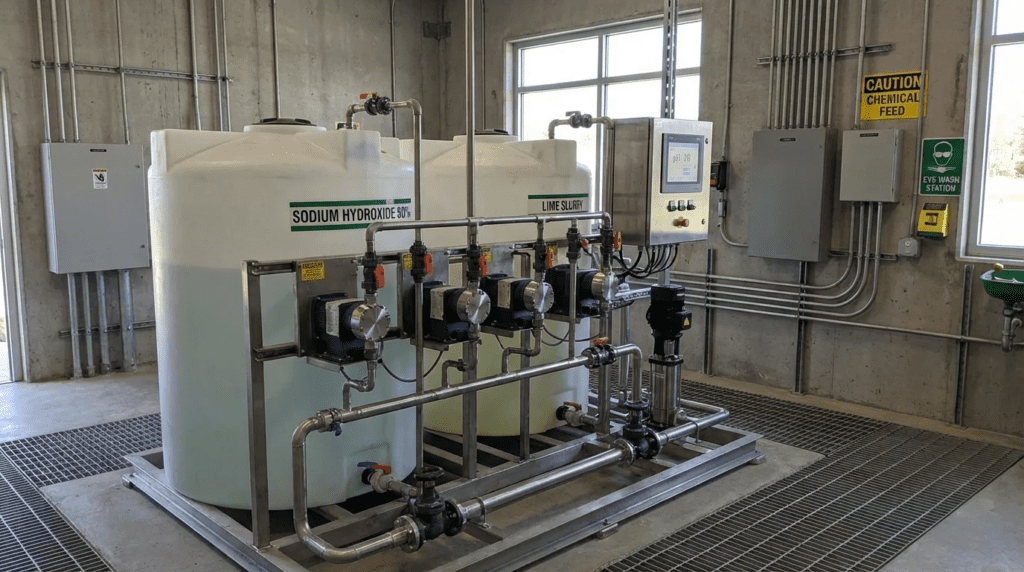
The reliability of pH and alkalinity control in wastewater treatment relies heavily on the physical infrastructure. The equipment involved is the same hardware covered across the site’s chemical dosing material, and packaged waste neutralization systems bundle the tanks, pumps, mixers, and controls into a single skid for industrial applications where site-built assembly is impractical.
- Metering Pumps: Peristaltic (hose) pumps are generally preferred for slurries (lime, mag hydroxide) or off-gassing liquids. Motor-driven diaphragm pumps are typical for clean liquids like caustic soda or sulfuric acid.
- Materials of Construction: Chemical compatibility is paramount. Concentrated sulfuric acid (>93%) requires carbon steel, stainless steel, or PTFE; however, dilute sulfuric acid will rapidly destroy carbon steel and requires CPVC or specialized plastics. Sodium hydroxide commonly utilizes CPVC, PVC, or cross-linked polyethylene (XLPE) tanks.
- Mixing Requirements: Because pH reactions are dependent on molecular contact, violent, high-energy mixing is required at the point of injection. Static mixers or mechanical rapid-mix basins are mandatory. Injecting chemicals into a slow-moving channel without mixing will result in chemical stratification and wild pH sensor fluctuations.
Controls, Automation & SCADA Integration
Because of the logarithmic titration S-curve, traditional Proportional-Integral-Derivative (PID) control often fails in pH neutralization.
- Feedback Control Challenges: If a standard PID loop relies solely on a downstream pH sensor, it will constantly overshoot. By the time the sensor detects the chemical change, too much chemical has already been pumped.
- Feed-Forward / Cascade Control: The best practice for variable flows requires a flow meter and an influent pH sensor. The flow meter provides a feed-forward signal to set the base pump speed (pacing). The downstream effluent pH sensor provides a secondary “trim” signal to slightly increase or decrease the dose based on the actual reaction.
- Multi-Stage Neutralization: For industrial systems requiring a shift from pH 2 to pH 7, engineers should specify a multi-stage approach. Tank 1 provides coarse adjustment (e.g., pH 2 to pH 5), and Tank 2 provides fine adjustment (pH 5 to pH 7.5). Trying to hit pH 7 in a single tank is practically impossible under variable loads.
COMPARISON TABLES
The following tables provide an engineering comparison of the primary chemicals used for pH and alkalinity control, followed by an application fit matrix to assist in selection based on specific plant constraints.
| Chemical Type | Primary Function | Key Engineering Advantages | Limitations & O&M Considerations | Typical Handling Requirements |
|---|---|---|---|---|
| Sodium Hydroxide (NaOH) | Strong pH Adjustment | Fast reacting; highly soluble; no sludge production. | Dangerous to operators; high risk of pH overshoot; 50% freezes at ~54°F. | Heated/insulated XLPE tanks; heat-traced CPVC piping; diaphragm pumps. |
| Magnesium Hydroxide, Mg(OH)2 | Alkalinity Buffering | Safe to handle; self-buffering at pH 9; high alkalinity density. | Heavy slurry; slow reaction time; solids settle out if unmixed. | Continuous tank agitation; peristaltic pumps; piping recirculation loops. |
| Calcium Hydroxide (Lime) | pH & Metals Precip. | Lowest material cost; excellent for heavy metal removal. | Massive sludge generation; severe scaling; high maintenance. | Dry silos, slakers, continuous flushing of slurry lines to prevent scaling. |
| Sodium Bicarbonate (NaHCO3) | Pure Alkalinity | Cannot over-raise pH; very safe; ideal for sensitive biology. | High cost per lb; typically requires on-site batch dissolution. | Dry bag/supersack handling; batch mixing tanks; progressive cavity or diaphragm pumps. |
| Carbon Dioxide (CO2) | pH Reduction (Acid) | Self-buffering (won’t drop pH below ~6.0); safe compared to mineral acids. | Higher equipment CAPEX; requires specialized dissolution diffusers. | Liquid CO2 bulk tanks; ambient vaporizers; gas injection panels. |
| Application Scenario | Primary Objective | Best-Fit Technology | Key Engineering Constraints |
|---|---|---|---|
| Large Municipal BNR Plant | Nitrification alkalinity support | Magnesium Hydroxide | Requires robust slurry agitation; slower reaction is fine given large basin detention times. |
| Small Municipal / Package Plant | Nitrification alkalinity support | 25% Sodium Hydroxide or Soda Ash | Lower capital budget restricts complex slurry handling; operators need simple liquid or dry bag systems. |
| Industrial Continuous Disch. | Rapid pH neutralization | Sulfuric Acid / 50% Caustic | Requires multi-stage reactor tanks; intense flash mixing; cascade flow/pH control loops. |
| Industrial Batch Discharge | Hold, neutralize, release | Dilute Acids / Dilute Caustic | Single equalization tank with recirculation pump; standard PID control is sufficient for batch modes. |
| Anaerobic Digester Recovery | Souring recovery (rapid VFA buffer) | Sodium Bicarbonate | Provides massive buffering without killing methanogens via extreme high-pH pockets. |
ENGINEER & OPERATOR FIELD NOTES
Commissioning & Acceptance Testing
Commissioning pH systems requires patience and rigorous loop tuning. Factory Acceptance Testing (FAT) should verify pump turn-down ratios and automated valve responses. During Site Acceptance Testing (SAT), engineers must verify the accuracy of the instrumentation. A critical SAT checkpoint is proving that the metering pump can reliably achieve its stated minimum flow rate without losing prime, as chemical dosing often runs at the very bottom of the pump’s curve during low-flow nighttime periods.
Common Specification Mistakes
- Ignoring Ambient Temperatures: Specifying 50% sodium hydroxide for outdoor storage in northern climates without redundant heat tracing and tank insulation. If the heat trace fails, the chemical solidifies, tearing apart pump diaphragms.
- Poor Sensor Placement: Installing the feedback pH probe too close to the chemical injection point. The chemical has not had time to fully mix, leading to “noisy” erratic readings. The probe must be placed downstream of the mixing zone, but not so far downstream that the lag time exceeds 30 to 60 seconds.
- Under-sizing Slurry Agitators: Magnesium hydroxide requires continuous, aggressive mixing. Undersized mixers leave dead zones in the tank, creating a dense sludge at the bottom that will eventually snap the mixer shaft.
O&M Burden & Strategy
The O&M burden of pH and alkalinity control in wastewater treatment is largely dictated by the chemical chosen. Slurry systems (lime, mag hydroxide) require automated water flush sequences every time the pump cycles off to prevent the slurry from hardening in the discharge piping.
Sensor maintenance is the highest labor component. pH probes must be cleaned and calibrated regularly. In greasy or heavily organically loaded wastewater, a standard pH glass electrode will foul within days. Operators should utilize automated hydraulic cleaning systems (water or air blast) or specify differential pH sensors, which utilize a reference cell that is highly resistant to contamination.
Day-to-day alkalinity management is as much a monitoring discipline as a chemical one. Guidance on understanding water alkalinity for treatment plants covers the sampling frequency, trending practices, and action thresholds that let operators see a buffer being consumed before the pH begins to move. Because alkalinity depletes silently while pH holds steady, a plant that monitors only pH has no warning at all until the buffer is gone — which is precisely why the alkalinity trend, not the pH trend, is the parameter worth alarming on.
Troubleshooting Guide
When pH control fails, the symptom is usually an out-of-compliance effluent, but the root cause is rarely the PLC.
- Symptom: Sluggish pH Response. If the PLC is commanding the pump to 100% but the basin pH is not changing, check for pump vapor lock (common if pumping sodium hypochlorite or out-gassing chemicals, though less common with caustic), check for a fouled/coated pH probe, or investigate a ruptured diaphragm.
- Symptom: Erratic, Jumping pH Readings. This usually indicates inadequate physical mixing at the injection point, or electrical ground loop interference in the sensor wiring. Ensure the process fluid is properly grounded.
- Symptom: Pump Cannot Maintain Prime. Check the suction lift. Chemical metering pumps push well but pull poorly. Ensure flooded suction whenever possible. Check the calibration column for leaks introducing air into the suction line.
DESIGN DETAILS & CALCULATIONS
Sizing Logic & Methodology
To properly size a chemical feed system for municipal BNR, consulting engineers must calculate the stoichiometric demand, account for native alkalinity, and add an appropriate safety margin. The wastewater-specific application of these methods is covered further in the material on pH adjustment in wastewater treatment, which addresses the influent variability and biological constraints that distinguish municipal dosing from clean-water applications.
Step-by-Step Nitrification Alkalinity Calculation:
- Determine Influent TKN: Total Kjeldahl Nitrogen (ammonia plus organic nitrogen) is the baseline. (e.g., 40 mg/L TKN).
- Calculate Assimilated Nitrogen: Some nitrogen is consumed for biomass growth (typically 5% of BOD removed). Subtract this from the TKN to find the Nitrified Nitrogen. (e.g., 40 mg/L TKN – 5 mg/L assimilated = 35 mg/L to be nitrified).
- Calculate Stoichiometric Demand: Multiply nitrified nitrogen by 7.14. (35 mg/L × 7.14 = 250 mg/L alkalinity demanded).
- Add Residual Requirement: Add the target effluent residual (typically 75 mg/L) to the demand. (250 + 75 = 325 mg/L Total Required).
- Account for Native Alkalinity: Subtract the plant’s native influent alkalinity (e.g., 150 mg/L). (325 – 150 = 175 mg/L Deficit).
- Account for Denitrification Credit (if applicable): If denitrifying, recover 3.57 mg/L per mg of nitrate reduced (e.g., assume 20 mg/L reduced × 3.57 = 71.4 mg/L recovered). New Deficit: 175 – 71.4 = 103.6 mg/L as CaCO3.
- Convert to Chemical Delivery Rate: Convert the daily mass deficit (lbs/day of CaCO3) into gallons per day of the specific chemical, using the chemical’s specific gravity, active concentration (%), and CaCO3 equivalence factor. (e.g., 1 lb of 50% NaOH provides ~0.63 lbs of alkalinity as CaCO3).
Specification Checklist
When drafting procurement specifications, ensure the following are clearly defined. Broader guidance on chemical feed systems covers the storage, containment, and pump selection decisions that sit behind each of these line items:
- Secondary Containment: Require double-wall tanks or distinct concrete containment berms sized for 110% of the largest single tank volume to comply with EPA/SPCC requirements.
- Skid Construction: Specify FRP (Fiberglass Reinforced Plastic), Polypropylene, or 316SS depending on the chemical. Wood or standard carbon steel skid bases will disintegrate in a chemical room environment.
- Pulsation Dampeners: Mandatory for diaphragm metering pumps to ensure a smooth, continuous flow into the process line and protect piping from water hammer.
- Calibration Columns: Must be sized to allow a minimum 30-second draw-down test at the pump’s maximum rated capacity.
Standards & Compliance
All chemicals utilized for municipal wastewater treatment that discharges into environmentally sensitive waters should conform to NSF/ANSI 60 standards for water treatment chemicals. Electrical components in hazardous industrial environments must comply with NEMA 4X (corrosion resistant/washdown) and appropriate NFPA/NEC explosion-proof classifications if dealing with flammable adjacent processes. Piping system materials should be designed according to ASME B31.3 Process Piping codes.
FAQ SECTION
What is the difference between pH and alkalinity in wastewater?
pH measures the current concentration of hydrogen ions, indicating how acidic or basic the water is at that exact moment. Alkalinity measures the water’s buffering capacity—its ability to absorb acids without allowing the pH to drop. You can have water with a neutral pH of 7.0 but zero alkalinity; the moment a biological process produces acid, the pH will plummet.
Why is pH and Alkalinity Control in Wastewater Treatment critical for nitrification?
Nitrifying bacteria consume massive amounts of alkalinity (7.14 mg per mg of ammonia oxidized). If the alkalinity is depleted, the pH drops. Nitrifying bacteria are highly pH-sensitive; their activity drops off significantly below pH 6.8 and halts completely around pH 6.0, resulting in high ammonia discharge violations.
How do you select the best chemical for pH adjustment?
Selection depends on the specific goal and budget. For rapid pH neutralization of industrial waste, strong liquid acids (sulfuric) or bases (caustic soda) are used due to fast reaction times. For biological alkalinity supplementation in municipal plants, magnesium hydroxide or sodium bicarbonate are preferred because they provide safer, stable, long-lasting buffering without risking extreme pH spikes.
How much does a chemical dosing system for pH control cost?
System costs vary wildly based on scale and chemical type. A simple, small-scale duplex metering pump skid for 25% caustic might cost $15K–$30K. A comprehensive, automated magnesium hydroxide storage and feed system with heated bulk tanks, redundant slurry agitation, and specialized pumps for a large municipal facility can range from $150K–$350K+ (typical/approximate).
How often should pH sensors be calibrated in a wastewater plant?
In highly fouling environments like primary clarifier effluent or industrial grease streams, probes may require manual cleaning and calibration weekly or even daily. In cleaner secondary effluent streams, bi-weekly to monthly calibration may suffice. Utilizing automated hydraulic cleaning (water blasts) and specifying differential pH probes significantly extends calibration intervals.
Why is controlling pH to exactly 7.0 difficult in industrial neutralization?
Because the pH scale is logarithmic, the titration curve has an “S” shape. Near pH 7.0, the curve is nearly vertical. A minuscule drop of strong chemical can jump the pH from 5 to 9 instantly. Engineering exact 7.0 control requires complex, multi-stage tank systems with precise cascade control loops and extensive mixing to prevent continuous over-shooting.
Can a plant have adequate pH but still be about to fail?
Yes, and this is the failure mode that catches plants off guard. Because alkalinity buffers the system, pH holds nearly steady while the buffer is being consumed, then drops sharply once it is exhausted — typically below 40 to 50 mg/L as CaCO3. A plant monitoring only pH sees no warning until the crash is already underway. Alkalinity should be trended and alarmed independently of pH, with the action threshold set well above the point where buffering collapses.
CONCLUSION
Key Takeaways: pH and Alkalinity Specification
- Separate the Metrics: Design for buffering capacity (alkalinity) in biological systems, and design for rapid hydrogen ion shifting (pH) in industrial neutralization systems.
- The 7.14 Rule: Always calculate the stoichiometric demand for biological nutrient removal; assume 7.14 mg of alkalinity consumed per mg of ammonia oxidized.
- Alarm on Alkalinity, Not pH: The buffer depletes silently while pH holds steady, so trending alkalinity is the only way to see a crash coming before it happens.
- Titration S-Curve Reality: Never attempt single-stage, single-tank neutralization for industrial wastewater requiring extreme pH shifts; multi-stage cascade control is mandatory.
- Chemical OPEX vs. CAPEX: Lime is cheap to buy but expensive to operate (sludge, scaling). Caustic is easy to pump but hazardous and requires heating. Mag Hydroxide is safe and buffers well but requires constant agitation.
- Mixing is Mandatory: Injecting chemicals without violent, high-energy mixing results in poor reaction kinetics and erratic, unstable sensor readings.
Implementing reliable pH and Alkalinity Control in Wastewater Treatment is one of the most mechanically and chemically complex challenges a utility or consulting engineer will face. The consequences of under-sizing or improperly configuring these systems are severe: biological washouts, permit violations, destroyed infrastructure from chemical scaling, and unsafe conditions for plant operators.
Successful design requires looking past simply buying a tank and a pump. Engineers must evaluate the specific titration curves of the wastewater, calculate the precise biological alkalinity demands, and choose a chemical that fits the maintenance capabilities of the facility. While cheap raw chemicals like lime may appeal to upfront OPEX calculations, the lifecycle labor costs of handling sludge and replacing scaled piping often negate those savings. Conversely, while caustic soda is mechanically simple to pump, the safety risks and need for heated containment must be meticulously designed.
Ultimately, a robust system relies on the synergy of reliable storage, proper pumping technology (peristaltic vs diaphragm), high-energy mixing, and sophisticated feed-forward control loops. By prioritizing accurate calculations, realistic operator burden, and chemical safety, engineers can deliver resilient systems that maintain process stability under the most demanding environmental and industrial loading conditions.