and Mitigation
INTRODUCTION
One of the most destructive and frequently misunderstood phenomena in municipal and industrial water systems is the hydraulic transient, commonly known as water hammer. When a pump suddenly loses power, or a valve closes too quickly, the kinetic energy of the moving fluid column is abruptly converted into pressure energy. This generates high-velocity pressure waves that travel through the piping network at the speed of sound in the fluid. Without proper transient analysis and Mitigation, these pressure spikes can easily exceed the pressure rating of the pipe, leading to catastrophic bursts, blown gaskets, damaged pipe supports, and premature fatigue of critical infrastructure.
Despite the severe financial and operational consequences, transient analysis is often treated as an afterthought during the design of pump stations, transmission mains, and force mains. Industry statistics suggest that up to 30% of sudden pipeline failures are directly attributable to unmitigated hydraulic transients. Furthermore, negative pressure waves (downsurges) can cause column separation and vacuum conditions, leading to pipe collapse or the intrusion of contaminated groundwater into potable systems.
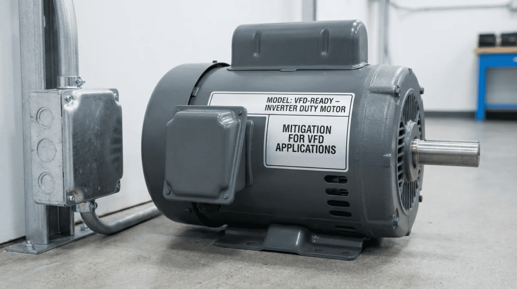
A critical specification mistake many engineers make is assuming that variable frequency drives (VFDs) or soft starters will eliminate water hammer. While these devices control routine start/stop sequences, they provide zero protection during a sudden power failure—the exact scenario that produces the most severe transient events. Proper surge protection requires dedicated mechanical equipment and a thorough understanding of system hydraulics.
This article provides consulting engineers, utility managers, and plant operators with an objective, highly technical guide to surge analysis and Mitigation. It covers the selection, specification, and maintenance of mitigation equipment—such as hydropneumatic surge tanks, air/vacuum valves, and surge anticipation valves—focusing strictly on real-world performance, constructability, and lifecycle cost in water and wastewater environments.
HOW TO SELECT / SPECIFY
Selecting the correct surge control strategy requires a comprehensive understanding of the pipeline’s hydraulic profile, the properties of the fluid, and the operational envelope of the pumping system. Equipment must be specified not just to survive steady-state conditions, but to rapidly respond to dynamic transient events.
Duty Conditions & Operating Envelope
The foundation of specifying surge protection equipment is defining the steady-state and transient operating envelopes. Engineers must establish the minimum and maximum static heads, the steady-state operating pressures, and the peak flow velocities. The critical parameter for transient events is the fluid velocity ($V$), as the magnitude of the pressure spike is directly proportional to the change in velocity ($Delta V$).
Operating modes drastically impact the mitigation strategy. A system operating continuously with infrequent stops will have a different risk profile than an intermittent lift station cycling 10 times an hour. Furthermore, future capacity considerations must be modeled. A surge vessel sized for a Phase 1 flow rate of 5 MGD may be entirely inadequate for a Phase 2 flow rate of 10 MGD. Mitigation equipment must be sized for the ultimate build-out conditions, or provisions must be made (such as blind flanges and pad space) for installing parallel mitigation devices in the future.
The physical properties of the fluid—specifically specific gravity, temperature, and bulk modulus—along with the pipe material’s modulus of elasticity, determine the wave celerity (wave speed). In ductile iron pipes, wave speeds typically range from 3,500 to 4,000 ft/s, whereas in HDPE, they may range from 1,000 to 1,500 ft/s. This dictates how quickly the transient wave travels and reflects, establishing the critical time period for valve closure and mitigation response.
Materials & Compatibility
In municipal and industrial applications, material selection dictates the longevity and reliability of surge mitigation equipment. Hydropneumatic tanks typically utilize either a bladder (to separate the air and water) or operate as a direct air-over-water system. For potable water applications, bladders must be NSF/ANSI 61 certified. Common bladder materials include Butyl or EPDM rubber. However, in systems dosing high concentrations of chloramines or chlorine dioxide, certain elastomers will degrade rapidly, necessitating the specification of specialized Viton or heavily compounded EPDM materials.
In wastewater applications (raw sewage or industrial effluent), abrasion and corrosion resistance are paramount. Raw sewage contains grit, rags, and high levels of hydrogen sulfide (H2S), which causes severe microbiologically influenced corrosion (MIC). Surge tanks in wastewater service should be specified with heavy-duty internal coatings, such as 100% solids epoxy (minimum 16-20 mils dry film thickness) or glass-lined interiors. If using air/vacuum valves on wastewater force mains, they must be highly elongated (tall body) to keep the mechanical float mechanism isolated from the grease and solids in the fluid. Components in contact with raw sewage should be 316 stainless steel to prevent rapid degradation.
Hydraulics & Process Performance
The hydraulic performance of surge mitigation equipment relies on its ability to seamlessly inject or remove energy/volume from the pipeline. For surge vessels, the critical performance metric is the usable expanded volume—the amount of water the tank can push into the pipeline during a downsurge to prevent vapor cavity formation and column separation. The pre-charge pressure of the vessel must be precisely calculated based on the steady-state hydraulic grade line (HGL) at the installation point.
If utilizing surge anticipation valves (SAVs), the process performance depends on pilot reaction time. An SAV must open quickly upon sensing a sudden pressure drop (the initial downsurge following a power failure) so that it is already fully open when the high-pressure return wave arrives. The capacity of the SAV to discharge water must be matched to the required flow reduction to keep the pressure within the pipe’s safe operating limits. Proper discharge routing—usually back to the wet well—is a critical process constraint, as the valve may dump thousands of gallons in seconds.
Installation Environment & Constructability
Constructability is frequently overlooked during the specification of mitigation equipment. Large hydropneumatic tanks (e.g., 500 to 10,000+ gallons) require significant structural foundations, seismic anchoring, and crane access for installation. When installed in underground vaults to prevent freezing or accommodate urban space constraints, the vault must be sized not just for the equipment, but for safe operator access, maintenance clearances, and bladder replacement.
Environmental conditions dictate ancillary equipment. In cold climates, water-bearing mitigation equipment installed above grade must be heavily insulated and heat-traced. Air/vacuum valves must be installed at high points in the pipeline profile; however, these locations may lack electrical power or be situated in environmentally sensitive areas. If an air valve discharges water during closure (a common issue known as “spitting”), proper drainage must be engineered. For compressor-based air-over-water systems, adequate ventilation and cooling for the air compressors are mandatory structural considerations.
Reliability, Redundancy & Failure Modes
Surge mitigation systems are life-safety and infrastructure-safety devices; their failure can lead to catastrophic pipeline ruptures. The most common failure mode for a bladder-style surge tank is the loss of pre-charge pressure due to a ruptured bladder or a leaking Schrader valve. If a tank becomes waterlogged, it provides zero surge protection. Therefore, specifications must include visual sight glasses, magnetic level indicators, or pressure transducers to monitor the gas volume.
Redundancy is critical in high-risk pump stations. Instead of specifying a single massive surge vessel, best practice often dictates specifying two vessels, each sized for 50-60% of the required transient volume, or sizing them such that if one is out of service for bladder replacement, the station can still operate at a reduced capacity without risking a main break. Critical spare parts, including replacement bladders, pilot rebuild kits for SAVs, and spare floats for air valves, must be mandated in the bid documents.
Controls & Automation Interfaces
Modern surge mitigation strategies integrate heavily with plant SCADA systems. While the mechanical response of a surge tank or an air valve is instantaneous and independent of electronics, monitoring their status is vital. Surge vessels should be equipped with electronic pressure transmitters and level probes. These instruments allow the PLC to continuously calculate the air-to-water ratio. If the air volume drops below the safe threshold, the SCADA system should generate a high-priority alarm and potentially inhibit pump starts until the pre-charge is restored.
For systems using automated compressor panels (air-over-water tanks), the control strategy must manage compressor cycling, automatic blowdown valves, and level control within tight deadbands. Instrumentation must be specified with appropriate environmental ratings (e.g., NEMA 4X or NEMA 7 explosion-proof for wastewater wet well proximity).
Maintainability, Safety & Access
Equipment that is difficult to maintain will not be maintained. Surge vessels must be installed with full-port isolation valves (typically gate or AWWA butterfly valves) to allow the vessel to be taken offline without shutting down the entire transmission main. Drain valves must be generously sized (minimum 2-inch to 4-inch) to allow the water side to be drained quickly during maintenance.
Safety is paramount when dealing with compressed gases. Hydropneumatic tanks are ASME Section VIII unfired pressure vessels. They must be equipped with ASME-certified pressure relief valves (PRVs) to prevent over-pressurization. Lockout/tagout (LOTO) provisions must be included on all isolation valves. Furthermore, confined space entry requirements should be minimized; whenever possible, locate air/vacuum valves and surge instrumentation above grade or in shallow, easily accessible enclosures rather than deep vaults.
Lifecycle Cost Drivers
When analyzing total cost of ownership (TCO) for surge equipment, engineers must weigh CAPEX against OPEX. Bladder tanks have a higher initial CAPEX than basic air-over-water tanks and require periodic bladder replacements (typically every 5-10 years), which is a significant labor and materials expense. However, bladder tanks do not require continuously operating air compressors, air filtration, or complex level controls, dramatically reducing energy consumption and routine OPEX.
Surge anticipation valves represent a lower CAPEX solution compared to massive pressure vessels, but they result in wasted treated water (or pumping energy in wastewater) because they dump fluid out of the system during a transient event. Furthermore, pilot-operated valves require highly skilled instrumentation technicians to calibrate and rebuild them—a labor burden that many small utility systems struggle to support. The TCO analysis must account for the utility’s specific workforce capabilities and energy costs.
COMPARISON TABLES
The following tables provide an objective comparison of the primary technologies and application scenarios used in transient control. Use these matrices to identify the most hydraulically appropriate and cost-effective approach based on your specific infrastructure constraints.
| Technology / Type | Features & Operation | Best-Fit Applications | Limitations & Constraints | Typical Maintenance |
|---|---|---|---|---|
| Bladder Surge Tanks | Pre-charged gas bladder expands/contracts to absorb pressure spikes and prevent column separation. | Potable water systems, wastewater force mains, high-head pump stations. | High footprint/weight. Bladder degradation over time. Fixed pre-charge pressure. | Check gas pre-charge quarterly. Bladder replacement 5-10 years. |
| Air-Over-Water Tanks | Direct contact between air and water. Uses compressors to maintain air volume. | Very large municipal transmission mains where bladder sizes are impractical. | Air dissolution into water requires continuous compressor operation. High OPEX. | Compressor servicing. Level probe cleaning. Auto-blowdown maintenance. |
| Surge Anticipation Valves | Pilot-operated valve opens on initial low pressure to vent incoming high-pressure wave. | Pumping into open reservoirs. Space-constrained stations. | Does NOT protect against negative pressure/column separation. Discharges large volumes. | Pilot calibration. Diaphragm inspection. Strainer cleaning. |
| Air/Vacuum Valves (Non-Slam) | Vents large volumes of air during fill, admits air during drain/surge, closes slowly to prevent secondary slam. | Pipeline high points. Long transmission lines with undulating profiles. | Vulnerable to freezing. Can clog in raw wastewater if not properly specified. | Annual flushing. Float and seal inspection. Clear insect screens. |
| Pump Flywheels | Adds rotational inertia to the pump shaft to extend spin-down time during power loss. | Short, low-head force mains. Systems with strict no-discharge requirements. | High bearing loads. Structural motor support needed. Limited mitigation capacity. | Bearing lubrication and vibration monitoring. |
| Application Scenario | Primary Risk Factor | Recommended Mitigation Strategy | Relative Cost | Operator Skill Required |
|---|---|---|---|---|
| Long Raw Water Transmission (Flat Profile) | Massive momentum; upsurge on pump restart | Large Air-Over-Water Tank + VFDs + 3-Stage Air Valves | $$$$ | High (Compressors, PLCs) |
| Wastewater Force Main (Undulating Profile) | Column separation at high points; H2S corrosion | Epoxy-lined Bladder Tank + Tall-Body Sewage Air Valves | $$$ | Moderate |
| High-Lift Finished Water Station (Steep Elevation) | Rapid wave return; extreme high-pressure spikes | Bladder Tank + Surge Anticipation Valve combination | $$$ | High (Pilot tuning) |
| Small Municipal Lift Station (Short run) | Check valve slam during routine stop | VFDs + Cushioned Swing Check Valves (No vessels needed) | $ | Low |
ENGINEER & OPERATOR FIELD NOTES
Theoretical modeling is only the first step. The true test of any transient control system occurs in the field. Bridging the gap between hydraulic models and real-world pump station operations requires strict commissioning protocols, robust maintenance strategies, and the avoidance of common specification pitfalls.
Commissioning & Acceptance Testing
Equipment that protects against catastrophic failure must be thoroughly tested before the system is turned over to the owner. The Factory Acceptance Test (FAT) for surge vessels should include a hydrostatic pressure test (typically at 1.5x design pressure) and a holiday test for internal epoxy linings to ensure there are no pinhole defects that could lead to rapid corrosion. For air-over-water panels, the FAT should verify PLC logic and compressor alternations.
The Site Acceptance Test (SAT) is the most critical phase. Once the equipment is installed, a transient test should be performed. This involves instrumenting the pipeline with high-speed data loggers (capable of recording pressure at 100+ samples per second) and deliberately inducing a pump trip by killing power to the main breakers. Standard SCADA systems, which poll every 1 to 5 seconds, are far too slow to capture a transient spike and will give a false sense of security. The high-speed trace must be compared against the hydraulic model predictions to verify that the mitigation equipment arrested the surge within the specified design limits.
Common Specification Mistakes
Many engineers assume that because a VFD ramps a pump down slowly over 30 seconds, water hammer is solved. However, during a utility power outage, the VFD instantly drops offline. The pump impeller spins down freely, governed only by its minimal inertia, causing sudden velocity changes and massive transient waves. VFDs manage routine stopping; they do absolutely nothing to mitigate power-fail transients.
Another frequent error in bid documents is under-sizing the connecting piping to a surge vessel. The vessel must inject water into the main line almost instantly. If the main line is 24 inches, connecting a massive surge tank with a 4-inch pipe introduces too much hydraulic friction. The vessel won’t be able to push water fast enough, rendering it useless. Connecting piping should generally be no less than one-third to one-half the diameter of the main header, and be kept as short and straight as possible.
Finally, engineers often forget to specify the exact pre-charge pressure for bladder tanks. The manufacturer cannot know the field conditions. The specification must clearly state the required gas volume and pre-charge pressure, which is calculated based on the station’s exact elevation and static head.
O&M Burden & Strategy
Mitigation equipment suffers from “out of sight, out of mind” syndrome. Because a surge tank only does its job during emergencies, it can fail silently. If a bladder ruptures and the tank fills with water, the operators will not notice anything is wrong during normal operation. The disaster only strikes when the power fails a year later.
Preventive maintenance (PM) schedules must mandate quarterly checks of the bladder pre-charge. This requires a specific procedure: the isolation valve must be closed, and the water side of the tank must be completely drained to atmospheric pressure before the air pressure gauge is read. Reading the air pressure while the tank is online to system pressure will only tell you the system water pressure, not the true gas pre-charge.
For wastewater air/vacuum valves, cleaning intervals should be aggressive (semi-annually). Fats, oils, and grease (FOG) can coat the interior mechanisms, causing the float to stick closed. A stuck air valve provides no vacuum relief, risking pipeline collapse.
Troubleshooting Guide
When operators report loud “banging” or pipe movement despite the presence of mitigation equipment, systematic troubleshooting is required:
- Symptom: Severe slamming upon routine pump stop.
Root Cause: The check valve is closing too slowly. By the time it shuts, the fluid column has already reversed direction, slamming the disc into the seat.
Solution: Retrofit with a fast-closing, spring-loaded non-slam check valve or adjust the VFD ramp-down time. - Symptom: Surge vessel shows correct pressure, but system still experiences water hammer during power loss.
Root Cause: The connecting pipe is heavily restricted. Check that the isolation valve is fully open. Ensure the tank’s internal perforated tube (if equipped) is not clogged with debris. - Symptom: Continuous water leaking from an air/vacuum valve.
Root Cause: Debris is caught between the float and the elastomeric seat, preventing a tight seal.
Solution: Isolate the valve, backflush it using the integral flush ports, and manually clean the seat.
DESIGN DETAILS / CALCULATIONS
Sizing Logic & Methodology
Sizing surge mitigation equipment is not a rule-of-thumb exercise; it requires specialized hydraulic modeling software (such as Bentley HAMMER, KYPipe Surge, or InfoWater Pro) utilizing the Method of Characteristics. However, engineers must understand the underlying physics to validate the model’s output.
The magnitude of the pressure spike generated by a sudden change in velocity is calculated using the Joukowsky Equation:
ΔP = (ρ · a · ΔV) / 144
Where:
ΔP = Change in pressure (psi)
ρ = Fluid density (slugs/ft³) (approx. 1.94 for water)
a = Wave celerity / speed of sound in the pipe (ft/s)
ΔV = Change in fluid velocity (ft/s)
The wave celerity (a) is highly dependent on the pipe material and wall thickness. Rigid pipes like ductile iron yield high wave speeds (up to 4,000 ft/s), generating massive pressure spikes. Flexible pipes like HDPE yield lower wave speeds (approx. 1,200 ft/s) because the pipe expands slightly, absorbing some energy.
When sizing a surge vessel, the model iterates to find a gas volume that will limit the deceleration of the fluid column. As a very rough check (not for final design), the total required vessel volume is often estimated at 10 to 20 times the volume of water displaced during the critical wave return period.
Specification Checklist
To ensure a robust procurement package, engineers should include the following in their mitigation equipment specifications:
- Vessel Design Code: Must be stamped in accordance with ASME Boiler and Pressure Vessel Code, Section VIII, Division 1.
- Working Pressure: Specify the design pressure (e.g., 150 psi, 250 psi) plus a 1.5x hydrostatic test requirement.
- Bladder Material: Specify NSF 61 EPDM for potable; heavily compounded Butyl/EPDM for wastewater. Note thickness requirements.
- Internal Coating: For wastewater, mandate 100% solids epoxy, holiday tested, minimum 16 mils DFT.
- Appurtenances: Require full-port isolation valves, minimum 2-inch drain valves, ASME safety relief valve, lifting lugs, and flanged connections.
- Instrumentation: Pressure gauges with isolation cocks; magnetic level indicators or pressure transducers wired to SCADA.
- Documentation: Require submittal of detailed buoyancy calculations (if installed in a vault), foundation loading data, and O&M manuals with specific pre-charge instructions.
Standards & Compliance
Compliance with established industry standards ensures long-term safety and interoperability. Air/vacuum valves and surge relief valves should conform to AWWA C512 (Air-Release, Air/Vacuum, and Combination Air Valves for Water and Wastewater Service). The design and layout of the mitigation strategy should align with the guidelines presented in AWWA M51 (Air-Release, Air/Vacuum, and Combination Air Valves).
For electrical components associated with air-over-water systems, control panels must meet UL 508A standards and NEMA classifications appropriate for the installation site. If installed in a wastewater wet well environment, NFPA 820 requires strict adherence to Class 1, Division 1 or Division 2 explosion-proof standards for all transducers and compressor connections.
FAQ SECTION
What is hydraulic transient analysis and Mitigation?
Hydraulic transient analysis is the engineering process of modeling pressure fluctuations (water hammer) caused by sudden changes in fluid velocity, such as pump power failures or rapid valve closures. Transient analysis and Mitigation involves designing and selecting equipment—like surge vessels, air valves, or flywheels—to absorb these energy waves, preventing pipeline bursts, gasket failures, and vacuum column separation.
How do you select the right surge vessel size?
Surge vessels cannot be sized using simple rules of thumb. Selection requires hydraulic modeling software using the Method of Characteristics. The engineer inputs the pipe diameter, length, profile, material (wave celerity), and pump curves. The software simulates a power failure and iterates vessel volumes to find a size that keeps the maximum and minimum pressure spikes within the safe operating limits of the pipeline components.
What’s the difference between a bladder tank and an air-over-water tank?
A bladder tank uses a heavy-duty rubber membrane to permanently separate the compressed air from the water, requiring no external air source once pre-charged. An air-over-water tank has no physical barrier; the air rests directly on the water surface. Because air naturally dissolves into water over time, air-over-water tanks require continuously operating air compressors, sensors, and control panels to maintain the required gas volume.
How much does surge mitigation equipment typically cost?
Costs vary drastically based on system size. Small bladder tanks (100-500 gallons) for lift stations typically cost $15,000 to $40,000. Large municipal bladder tanks (5,000-10,000 gallons) can range from $150,000 to over $300,000. Surge anticipation valves are generally lower in capital cost ($10,000-$30,000) but have higher lifetime operational costs due to water waste and complex maintenance.
How often should a surge vessel be maintained?
For bladder tanks, operators must verify the gas pre-charge pressure quarterly. This requires isolating the tank and draining the water completely before checking the air pressure. Bladders generally have a lifespan of 5 to 10 years depending on water chemistry and cycling frequency. Air-over-water systems require monthly maintenance of the compressors, blowdown valves, and level probes.
Why does water hammer occur even when I have a VFD?
A Variable Frequency Drive (VFD) only controls the motor during routine, powered operations (slow starts and stops). During a sudden utility power failure, the VFD instantly shuts down. The pump loses all driving torque, and the fluid column comes to a rapid, uncontrolled halt. Mechanical surge equipment is mandatory to handle these instantaneous, unpowered deceleration events.
What are the primary methods of surge control and Mitigation?
The primary mechanical methods include installing hydropneumatic surge tanks (to inject water during a downsurge and absorb pressure during an upsurge), air/vacuum valves (to vent air and prevent vacuum conditions), surge anticipation valves (to discharge high-pressure waves out of the system), and pump flywheels (to increase spin-down time and slowly decelerate the fluid).
CONCLUSION
KEY TAKEAWAYS
- VFDs are not surge protection: Mechanical mitigation is required to handle sudden utility power failures, which cause the most severe transients.
- Model for worst-case: Always base surge analysis on simultaneous pump trips at maximum build-out flow and worst-case static head conditions.
- Connection sizing matters: Surge vessels must have generously sized, short connecting piping to ensure rapid energy transfer. Restrictive piping renders tanks useless.
- Maintenance is mandatory: Bladder tanks must be physically isolated and drained quarterly to accurately check gas pre-charge pressure.
- Material compatibility: Specify heavily compounded elastomers and 100% solids epoxy linings for wastewater environments to combat H2S and abrasion.
Approaching hydraulic transient analysis and Mitigation requires a paradigm shift for many design engineers. Rather than viewing surge equipment as an optional accessory, it must be treated as critical, life-safety infrastructure. The forces generated by sudden changes in fluid velocity—governed by the Joukowsky equation and the elasticity of the pipeline—are easily capable of destroying newly installed multi-million-dollar transmission mains.
Engineers and utility operators must work collaboratively to balance capital constraints with operational realities. While large air-over-water vessels or surge anticipation valves might appear cost-effective during the design phase, their demanding maintenance profiles and requirement for highly skilled instrumentation technicians often burden small utility staffs. In many cases, slightly higher CAPEX for passive bladder-style surge tanks yields a significantly lower Total Cost of Ownership and a more reliable mitigation strategy.
Ultimately, a successful mitigation project relies on rigorous initial hydraulic modeling, precise specification of materials and connection hydraulics, mandatory Factory and Site Acceptance Testing with high-speed data loggers, and a strict adherence to preventive maintenance schedules. When engineers prioritize these factors, they ensure the integrity of the hydraulic network, protect public infrastructure from catastrophic failure, and drastically extend the operational lifespan of the system.