
Mud Valves Automation: Actuation Options
Introduction
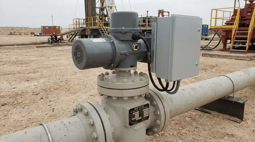
For decades, operators at municipal water and wastewater treatment facilities have relied on manual T-wrenches and high-geared floor stands to actuate tank bottom valves. This reliance creates a significant operational bottleneck. The time-consuming, physically demanding process of manually unseating valves under high hydrostatic head often results in infrequent desludging, compromised effluent quality, and severe ergonomic risks. Furthermore, manual operation inherently isolates the desludging process from modern SCADA control, preventing the implementation of optimized, automated batch-blowdown strategies. This brings us to a critical inflection point in modern plant design: Mud Valves Automation: Actuation Options.
Mud valves—often referred to as sludge valves, plug drain valves, or tank bottom valves—are specialized components installed at the lowest elevation of clarifiers, sedimentation basins, holding tanks, and equalization basins. Their primary function is the reliable evacuation of settled solids, grit, and heavy sludge. Because they reside entirely submerged, usually covered by meters of dense, abrasive media, and are connected to surface-level operators via long extension stems, automating them requires strict engineering oversight. A poorly specified actuator or an undersized stem can lead to buckled extension rods, burned-out motors, or valves stuck in the open position, ultimately requiring a complete basin drain-down to repair.
Mud valves sit at the severe-service end of the broader family of valves used in water treatment plants, and they are unusual within it in two respects. First, the valve is permanently inaccessible during operation, so every decision about it has to anticipate a failure that cannot be inspected without taking the basin out of service. Second, the actuator is separated from the valve by several meters of slender stem, which means the automation problem is as much a structural one as an electrical one. Engineers who approach a mud valve the way they would approach an accessible in-line valve routinely undersize the actuator, omit the stem guides, or configure the closing sequence in a way that guarantees leakage within a few years.
Proper selection and specification of Mud Valves Automation: Actuation Options directly impacts a facility’s process performance and lifecycle maintenance burden. If an engineer specifies an electric actuator with insufficient unseating torque, or fails to account for the necessary stem guides, the system will reliably fail during cold-weather or high-sludge-blanket events. Conversely, over-specifying actuation packages without considering the plant’s existing power infrastructure or maintenance capabilities wastes capital budget.
This technical article provides consulting engineers, plant managers, and utility decision-makers with a comprehensive framework for specifying mud valve automation. It evaluates the engineering tradeoffs between electric, pneumatic, and hydraulic actuation, details critical mechanical sizing calculations, and provides actionable field notes for commissioning and long-term operations.
Subcategory Overview
Mud valve work divides into three distinct engineering problems, each governing at a different stage of the asset lifecycle. The subsections below outline what each area covers and when it becomes the controlling consideration.
Mud Valve Manufacturers
The supplier landscape for tank bottom valves is narrower than for most valve categories, which makes coverage of the top mud valve manufacturers more consequential than it would be for a commodity product. Very few manufacturers build mud valves as a primary line, and most who do also supply slide gates, floor stands, and extension stem hardware, which matters because sourcing the valve, stem, guides, and operator from a single responsible party eliminates the interface gaps that cause most field problems. Vendor evaluation should focus on a handful of specific capabilities: whether the manufacturer performs the stem buckling calculation and takes responsibility for guide spacing, whether resilient seats are field-replaceable or require removing the valve body from the basin floor, what coating system is applied and to what standard, and whether the supplier can furnish an actuator sized and mounted as part of the same package. On public bid work, the thin supplier base also means the specification needs care to name enough qualified manufacturers to satisfy competitive procurement without admitting a product that cannot meet the service.
Mud Valve Maintenance and Failure Modes
Because a mud valve cannot be inspected in service, mud valves maintenance is a discipline built almost entirely on indirect evidence and planned access windows. The failure modes are well catalogued and mostly progressive rather than sudden: resilient seats harden and abrade until drop-tight shutoff is no longer achievable, bronze seating faces erode under grit-laden flow, stem threads gall from lost lubrication, guides wear until the stem runs out of alignment, and coating breakdown on the valve body allows corrosion to roughen the seating surface. Each of these announces itself before it becomes critical, provided someone is watching the right signal. Rising unseating torque over successive operations, gradually increasing leakage when the valve is commanded closed, and changes in stroke time are all early indicators. Field repairs that can be executed during a drain-down include seat replacement, stem straightening or replacement, guide re-shimming, and coating touch-up, and planning which of these to do in a single outage is the difference between one basin drain and three.
Mud Valves in Chemical Service
Standard cast iron and bronze construction is adequate for municipal sludge but fails quickly in chemical duty, which is why mud valves for chemical systems is treated separately. Chemical storage tanks, neutralization basins, and industrial sedimentation units draining acidic, caustic, or oxidizing residuals require material selection driven by the specific chemistry rather than by a general corrosion allowance. The considerations extend past the valve body to every component in the assembly: seat elastomer compatibility, stem and fastener metallurgy, coating chemical resistance, and the packing or sealing arrangement at the stem penetration. Safety obligations also change. A chemical service mud valve is a potential release point, which brings secondary containment, material compatibility documentation, and in some cases fail-safe actuation into scope where a municipal sludge valve would simply fail in place.
How to Select / Specify Mud Valves Automation: Actuation Options
Specifying the optimal automated actuation system for a mud valve requires a holistic analysis of the mechanical, hydraulic, and environmental conditions. The actuator cannot be selected in isolation; it must be treated as the prime mover in a mechanical power transmission system that includes the floor stand, extension stem, stem guides, and the valve plug itself. The general principles governing actuators in water and wastewater service all apply here, but the extension stem changes the problem materially: thrust that would be trivially transmitted across a few inches of coupling becomes a column stability question across several meters of slender rod.
Duty Conditions & Operating Envelope
The operating envelope dictates the required thrust, torque, and duty cycle of the actuator.
- Hydrostatic Head and Pressures: Mud valves typically face low to moderate pressures (usually 10 to 40 feet of head, or approx. 4.3 to 17.3 psi), but this pressure acts directly on the area of the valve plug. The actuator must overcome this static head to open the valve (unseating).
- Operating Modes: Mud valves generally operate in open/close (on/off) service rather than modulating service. Continuous throttling of heavy sludge causes rapid erosion of the resilient seats. Therefore, automation should be specified for intermittent, discrete operation.
- Duty Cycle: While clarifier blowdown might only occur a few times per day, automated sequences might trigger the valve every few hours for shorter durations. Actuators should be rated for minimum 60 starts per hour to accommodate automated flushing sequences and SCADA hunting, though standard mud valve duty is typically much lower.
Adjacent Devices and Alternatives
A mud valve is not always the right device for the duty, and the specification is stronger when the alternatives have been considered and rejected on record. Where the requirement is isolating a channel, controlling flow between basins, or dewatering a structure rather than draining solids from a tank floor, the correct device is usually a slide or sluice gate. Mud valves and gates share nearly all of their actuation hardware, including floor stands, extension stems, guides, and AWWA C542 electric operators, which is why the two frequently appear on the same submittal and why an engineer specifying one should be fluent in the other.
Where the requirement is throttling or frequent cycling on a sludge line rather than infrequent bottom drainage, an in-line valve is generally the better choice. Eccentric plug valves are the established alternative for sludge draw-off service, offering a wiping seating action that tolerates grit, a quarter-turn operation that suits frequent cycling, and accessibility for maintenance that a submerged tank bottom valve can never provide. The trade-off is that a plug valve cannot sit at the lowest point of a basin floor, so the two are complements rather than substitutes: the mud valve drains the tank, the plug valve controls what happens downstream of it.
Materials & Compatibility
Because the valve and stem are submerged in corrosive wastewater or chemical sludge, material specification is critical to prevent binding that will overload the actuator.
- Valve Body and Plug: Cast iron (ASTM A126 Class B) or Ductile iron (ASTM A536) coated with an AWWA-compliant fusion-bonded epoxy (FBE) is standard.
- Seating Surfaces: Bronze to bronze, or bronze to resilient rubber (Buna-N or EPDM). Resilient seats provide drop-tight shutoff but require higher seating thrust from the actuator to compress the elastomer.
- Extension Stems: Minimum 304L stainless steel, though 316L stainless steel is strongly recommended for municipal wastewater to prevent pitting corrosion from hydrogen sulfide (H2S).
- Actuator Housing: The actuator itself, typically mounted above the grating on a floor stand, should feature an aluminum or ductile iron enclosure with robust marine-grade polyurethane or epoxy coatings.
Hydraulics & Process Performance
Mud valves are designed for high-capacity gravity drainage or pump suction. They do not have linear flow characteristics. Automation speed must align with process constraints.
- Stroke Speed: An actuator stroke speed of 12 inches per minute is typical. Opening a 12-inch mud valve too rapidly can cause hydraulic shock or structural stress on the basin floor if tied to a high-suction positive displacement pump.
- Vortexing: If automated valves are held open too long, vortexing can draw air into sludge transfer pumps. SCADA integration must include timing logic to close the valve before the sludge blanket is entirely depleted.
Installation Environment & Constructability
The physical mounting of the actuator significantly impacts long-term reliability.
- Structural Considerations: The floor stand must absorb the full reactionary thrust of the actuator during closing (seating) and opening (unseating). Concrete mounting pads must be sized for maximum stall torque/thrust of the actuator, not just the running torque.
- Space Constraints: Electric actuators require electrical clearance (typically 36 inches per NEC) for maintenance. Pneumatic cylinders can be more compact but require routing of rigid air lines.
- Stem Guiding: This is a highly critical constructability factor. To prevent the extension stem from buckling under the compression load of closing the valve, intermediate stem guides must be installed to maintain the proper unsupported length-to-radius (L/r) ratio (typically L/r < 200).
Reliability, Redundancy & Failure Modes
Automated mud valves face unique failure modes due to the unseen nature of the valve body.
- Debris Blockage: The most common failure mode is debris (rags, grit, rocks) wedged between the plug and the seat. The actuator must have precision torque-limiting switches to stop the motor before bending the stem or damaging the valve body.
- Sludge Compaction: If a basin sits idle, sludge can compact and harden over the valve. The actuator must have sufficient unseating torque margin (often a 1.5x to 2.0x safety factor over calculated unseating thrust) to break the plug free.
- Fail-Safe Requirements: In power loss scenarios, engineers must decide if the valve should fail-in-place (typical for electric actuators), fail-close (requires spring-return pneumatic or hydraulic, or battery-backup electric), or fail-open. Mud valves typically fail-in-place to prevent sudden basin draining or pump dead-heading.
Pro Tip: Torque Overload Protection. When specifying electric actuators for mud valves, clearly mandate that the actuator’s internal torque switches be wired to interrupt the motor contactor directly, bypassing SCADA delays. This hardware-level protection is critical to prevent catastrophic stem buckling when a mud valve closes on a hard obstruction like a rock or a dropped tool.
Controls & Automation Interfaces
Modern Mud Valves Automation: Actuation Options must integrate seamlessly into plant architectures.
- Limit and Torque Switches: Minimum requirement includes discrete open/close limit switches and open/close torque switches.
- Network Protocols: While hardwired discrete signals (4-20mA position, 24VDC/120VAC commands) remain common, digital protocols (EtherNet/IP, Modbus TCP, PROFINET) reduce wiring costs and provide rich diagnostic data (e.g., historical torque profiles).
- Local Control: Actuators must include a local/off/remote (LOR) selector switch, local open/close pushbuttons, and a mechanical handwheel for manual override.
Maintainability, Safety & Access
- Handwheel Declutching: The manual override handwheel must safely disengage when the motor starts to prevent operator injury (a non-rotating handwheel during motor operation is a strict AWWA C542 requirement).
- Lubrication: Actuators utilizing an Acme threaded stem nut require regular greasing. Specify accessible zerk fittings or automatic greasers.
- Lockout/Tagout (LOTO): Electrical disconnects must be lockable in the OFF position. For pneumatic systems, block-and-bleed valves are required.
Lifecycle Cost Drivers
Selecting the lowest capital expenditure (CAPEX) option often leads to higher total cost of ownership (TCO) in mud valve applications.
- Electric Actuators: Highest CAPEX per unit, lowest maintenance OPEX. Excellent data feedback.
- Pneumatic Actuators: Lower unit CAPEX, but high plant-wide OPEX due to the energy intensity of generating compressed air, instrument air dryer maintenance, and air leak mitigation.
- Hydraulic Actuators: High CAPEX (requires hydraulic power units). Used primarily where massive thrust is required in a very compact footprint, but poses environmental risks (fluid leaks into the process).
Comparison Tables
The following tables provide an engineering comparison of the primary Mud Valves Automation: Actuation Options and a matrix to assist in matching the correct technology to specific plant environments. These tables evaluate objective mechanical capabilities and lifecycle impacts.
| Technology / Type | Primary Features & Capabilities | Best-Fit Applications | Limitations / Considerations | Typical Maintenance Profile |
|---|---|---|---|---|
| Electric Motor Actuator (EMA) (Multi-turn) |
High unseating torque; native digital communications; integral motor controls; non-rotating manual handwheel; precise torque limiting. | Most municipal WWTPs; remote pump stations; SCADA-integrated automated sludge blowdown systems. | High initial CAPEX; requires 3-phase power routing; fails-in-place upon power loss (unless UPS equipped). | Low. Annual visual inspection, periodic stem nut greasing, oil bath change every 3-5 years. |
| Pneumatic Cylinder (Linear) |
Rapid stroke speeds; linear thrust directly maps to valve action; easy to configure fail-safe (spring return or accumulator). | Industrial wastewater; facilities with robust, existing instrument-air infrastructure; hazardous (classified) locations. | Requires clean, dry air (dew point suppression); seals degrade over time; complex speed control (requires flow controls). | Moderate to High. Air line leak checks, cylinder seal replacement (3-7 years), air compressor/dryer maintenance. |
| Hydraulic Cylinder (Linear) |
Highest power density (thrust-to-size ratio); extremely smooth operation; centralized hydraulic power unit (HPU) can run multiple valves. | Massive primary clarifiers; heavy industrial sludge; limited overhead clearance installations. | High system complexity; risk of hydraulic fluid leaks into treatment process; requires HPU maintenance. | High. Fluid sampling/replacement, filter changes, high-pressure hose inspections, pump maintenance. |
| Portable Actuator (Electric or Pneumatic tool) |
Drives standard 2″ square AWWA nuts or handwheels on floor stands; low cost; one tool services many valves. | Small municipalities; very infrequent desludging operations; budget-constrained retrofits. | Not automated (requires operator presence); no SCADA integration; high physical labor and setup time. | Low. Tool battery/motor maintenance. Floor stands require standard manual greasing. |
| Application Scenario | Plant Size / Type | Key Constraints | Recommended Actuation | Relative CAPEX / OPEX Impact |
|---|---|---|---|---|
| Frequent automated clarifier blowdown (every 2-4 hours) | Medium to Large Municipal | Requires reliable SCADA feedback, low wear, minimal operator intervention. | Electric Motor Actuator with multi-turn gearbox. | High CAPEX / Low OPEX |
| Hazardous / Explosive Atmosphere (NFPA 820 Class 1 Div 1) | Industrial / Digester Proximity | Strict explosion-proof requirements; electrical sparks are a high risk. | Pneumatic Cylinder (all electrical controls located remotely outside classified area). | Medium CAPEX / Medium OPEX |
| Deep basins with highly abrasive/heavy grit loads | Primary Treatment / Grit Chambers | Very high unseating thrust required; risk of stem buckling. | Electric Actuator (oversized by 50%) or Hydraulic Cylinder. Robust stem guides mandatory. | High CAPEX / Medium OPEX |
| Winterized outdoor basins subject to freezing | Northern Climates | Pneumatic airlines prone to freezing condensation; oils become viscous. | Electric Motor Actuator equipped with internal space heaters and low-temp lubricants. | High CAPEX / Low OPEX |
| Budget-restricted infrequent desludging | Small Municipal / Lagoon | Capital funds unavailable for full SCADA tie-in and conduit runs. | Portable Actuator driven manually on existing floor stands. | Low CAPEX / High Labor OPEX |
Engineer & Operator Field Notes
Translating a specification into a functioning system requires rigorous oversight during construction, commissioning, and handover. The following field notes address the practical realities of deploying Mud Valves Automation: Actuation Options.
Commissioning & Acceptance Testing
Commissioning an automated mud valve is delicate because the valve itself cannot be seen. Proper configuration of the actuator’s limit and torque settings must be completed before the basin is filled.
- Dry Stroking: Before introducing water or sludge, the valve must be operated fully open and closed. Operators must verify that the actuator strokes smoothly without binding, and that the extension stem remains plumb and true through all guides.
- Setting the Close Limit (Seating): Mud valves should typically be torque-seated, not limit-seated. The actuator drives the valve closed until the plug firmly engages the seat and hits the pre-set torque threshold. If set by position (limit), thermal expansion of the long stem or minor debris could prevent complete closure or cause the motor to burn out trying to reach an impossible position.
- Setting the Open Limit (Unseating): The open position should be set by position (limit switch), not torque. The valve opens until it reaches the desired maximum stroke.
- Site Acceptance Test (SAT): The SAT should include verifying manual handwheel override under load, verifying SCADA feedback signals (Open, Closed, Fault, Remote mode), and confirming fail-safe behavior during simulated power loss.
- Baseline Torque Record: Capture and archive the full open and close torque profile at commissioning while the valve, seat, stem, and guides are all new. Every subsequent diagnosis of a binding or leaking valve depends on having that reference, and it cannot be recreated later.
Common Mistake: Limit-Seating a Mud Valve. Setting an automated mud valve to close based on a mechanical position limit rather than a torque limit is a primary cause of leakage. As the resilient seat wears over years of use, a limit-seated valve will no longer compress the rubber adequately, resulting in constant sludge leakage. Always torque-seat mud valves.
Common Specification Mistakes
Engineers writing bid packages frequently overlook the nuances of submerged mechanical linkages.
- Omitting Stem Guide Requirements: Specifying the actuator and the valve without clearly defining the responsibility for the extension stem and guides. The actuator manufacturer, valve manufacturer, or contractor must be assigned responsibility for performing the Euler column buckling calculations and providing necessary 316SS wall brackets.
- Ambiguous Torque Safety Factors: Stating “provide an actuator sized for the valve” is insufficient. Specifications must demand a minimum 1.5x unseating torque safety factor based on maximum differential pressure plus a “stuck plug” allowance.
- Ignoring Speed Control on Pneumatics: When specifying pneumatic cylinders, failing to require exhaust speed control valves (flow controls). Without them, the cylinder will slam the heavy cast iron plug into the seat, causing structural damage.
- Leaving Seat Replacement Access Undefined: Resilient seats are consumables with a five to ten year life, but the specification rarely states whether replacement can be performed from above with the basin drained or requires removing the valve body from the floor. That distinction determines whether a seat change is a one-day outage or a major operation.
- Splitting the Package Across Divisions: Where the valve, the stem and guides, the floor stand, and the actuator are procured under separate specification sections, the interfaces belong to nobody. Assign single-source responsibility for the complete assembly, or name the party responsible for coordination explicitly.
O&M Burden & Strategy
Once operational, the longevity of the system depends on a proactive maintenance strategy.
- Routine Inspection (Monthly): Visually inspect the floor stand, check for unusual vibrations during operation, and confirm the actuator’s LCD screen displays no fault codes.
- Preventive Maintenance (Semi-Annual): Generously grease the rising stem threads and the actuator drive nut. For pneumatic systems, drain condensation from air-prep units and verify lubricator oil levels.
- Predictive Maintenance: Modern intelligent electric actuators can log torque profiles over time. If the torque required to open the valve increases slowly over several months, it indicates scale buildup on the valve seat, stem binding, or failing guides—allowing operators to schedule a basin drain-down before catastrophic failure occurs.
- Exercise Schedule: Valves that sit in one position for months accumulate scale on the stem threads and compacted solids over the plug. A monthly full-stroke exercise, logged with its torque reading, both keeps the mechanism free and generates the trend data that predictive maintenance depends on.
Troubleshooting Guide
When an automated mud valve system malfunctions, identifying the root cause quickly prevents cascading damage.
- Symptom: Actuator trips on “Torque Fault” during closing.
- Root Cause: Debris (rag, rock, grit pile) is trapped between the plug and seat.
- Fix: Reverse the actuator to open the valve fully, allowing flow to flush the debris, then attempt to close again. Do not bypass the torque switch to force it closed; this will bend the stem.
- Symptom: Actuator motor runs, but valve position does not change.
- Root Cause: Stripped drive nut in the actuator, snapped extension stem, or sheared coupling pin.
- Fix: Requires physical inspection of the linkages. Isolate power, manually test stem integrity, and replace broken components.
- Symptom: Sludge continues to drain when valve indicates “Closed.”
- Root Cause: Worn resilient seat, insufficient closing torque setting, or limit-seating error.
- Fix: Increase closing torque setting incrementally (within safe mechanical limits). If leakage persists, the basin must be drained to inspect/replace the resilient seat.
- Symptom: Unseating torque has climbed steadily over several months.
- Root Cause: Scale accumulation on the seat, stem thread galling, guide wear pulling the stem out of alignment, or coating breakdown roughening the seating surface.
- Fix: Compare against the commissioning baseline to gauge severity, grease the stem and drive nut, and schedule a drain-down inspection before the trend reaches the actuator’s torque limit.
Design Details / Calculations
Quantifying the mechanical forces is the core engineering task when designing Mud Valves Automation: Actuation Options. Relying entirely on vendor sizing charts without understanding the underlying physics can lead to undersized equipment.
Sizing Logic & Methodology
The sizing of a multi-turn electric actuator for a rising-stem mud valve requires calculating the total thrust required, and then converting that thrust to the torque required at the drive nut.
Step 1: Calculate Total Required Thrust (Ftotal)
The total thrust required to unseat the valve is the sum of the hydrostatic force and the seating friction/sticking force.
Ftotal = Fhead + Ffriction + Fsticking
- Fhead is the area of the plug face multiplied by the maximum hydrostatic head pressure.
- Ffriction is drag from stem guides and packing, often estimated at 10 to 15 percent of Fhead.
- Fsticking is an empirical allowance for sludge compaction. AWWA guidelines often suggest adding 50 to 100 percent of the static head force for heavy sludge.
Step 2: Convert Thrust to Torque (Treq)
Because the actuator turns a threaded nut to lift a threaded stem, the efficiency of those threads dictates the torque.
The Stem Factor is a mathematical constant derived from the thread pitch, lead, and coefficient of friction (typically Acme threads with a friction coefficient of 0.15 to 0.20). An Acme thread is notoriously inefficient (often 30-40% efficiency), meaning much of the motor’s torque is consumed overcoming thread friction.
Step 3: Check Stem Buckling (Compressive Load)
When closing the valve, the actuator pushes down on the stem. The stem must not buckle. Using Euler’s column formula:
Engineers must ensure the maximum stall thrust of the actuator is less than the critical buckling load (Pcr) of the stem segment between guides. Because the critical load falls with the square of the unsupported length, halving the guide spacing quadruples the buckling capacity, which is why adding an intermediate guide is almost always cheaper than increasing stem diameter.
Specification Checklist
To ensure robust bids and reliable equipment, utility engineers should include the following items in their specification sections (typically Division 40 Process Interconnections or Division 43 Process Gas and Liquid Handling):
- Actuator Sizing Criteria: Explicitly state maximum static head, process fluid density, required stroke time, and a minimum 1.5 unseating safety margin.
- Enclosure Ratings: Specify NEMA 4X (watertight, corrosion-resistant) minimum for outdoor or corrosive indoor applications. Specify NEMA 6P (submersible) if the actuator is in a dry pit prone to flooding.
- Manual Override: Demand a handwheel that does not rotate during motor operation and requires less than 40 lbs of rim pull to operate under maximum load.
- Stem Thread Protection: Require clear polycarbonate or steel stem covers to protect the greased threads from airborne dust, grit, and UV degradation.
- Materials: Bronze drive nut, 316SS stem, 316SS fasteners.
- Stem and Guide Responsibility: Name the party responsible for the Euler buckling calculation, guide spacing, and supply of intermediate guide brackets, and require the calculation as a submittal.
- Seating Configuration: State explicitly that the valve shall be torque-seated closed and limit-stopped open, with both settings recorded at commissioning.
- Baseline Torque Data: Require the commissioning contractor to deliver the open and close torque profile as a closeout document.
- Seat Replacement Method: State whether the resilient seat must be replaceable from above with the basin drained, and require the manufacturer to describe the procedure.
Standards & Compliance
Adherence to industry standards ensures safety, interoperability, and long-term support.
- AWWA C542: Electric Motor Actuators for Valves and Slide Gates. This is the gold standard for specifying EMAs in water/wastewater.
- AWWA C541: Hydraulic and Pneumatic Cylinder and Vane-Type Actuators for Valves and Slide Gates.
- AWWA C500 / C561: While specifically for gate valves and slide gates, the stem sizing, threading, and guide spacing rules in these standards are universally applied to mud valve extension stems.
- ASTM A126 and ASTM A536: Gray iron and ductile iron castings, governing valve body and plug material.
- NFPA 820: Fire Protection in Wastewater Treatment and Collection Facilities, determining electrical area classification where an actuator is installed near digesters or enclosed wet areas.
- IEEE / UL / CSA: Electrical components must bear appropriate certifications for the region of installation.
Frequently Asked Questions
What is a mud valve and where is it used?
A mud valve (or sludge valve) is a heavy-duty plug-style valve installed at the very bottom of clarifiers, sedimentation basins, or tanks in water and wastewater treatment plants. It is used to periodically drain accumulated sludge, grit, and heavy sediment via gravity or pump suction. They are operated from above the water line using extension stems.
Why is it important to automate mud valves?
Automating mud valves eliminates the dangerous, physically intensive labor of manually cranking heavy valves open against high water pressure. Automation allows for integration with plant SCADA systems, enabling high-frequency, optimized batch blowdown sequences that improve clarifier efficiency, maintain consistent sludge blanket depths, and improve overall effluent quality.
What is the difference between limit seating and torque seating for automated mud valves?
Limit seating stops the actuator when the valve reaches a specific physical position. Torque seating stops the actuator when the motor senses a specific resistance (torque) level. Mud valves should always be torque-seated to ensure the plug firmly compresses the resilient rubber seat for a drop-tight seal, compensating for seat wear over time.
How do you calculate the required actuator torque for a mud valve?
Required torque is calculated by first determining the total unseating thrust (Valve Area × Hydrostatic Pressure + Stem Friction + Sludge Compaction Safety Factor). That total thrust is then multiplied by the “Stem Factor,” a value based on the geometry and friction coefficient of the Acme threaded stem, to convert linear thrust into the rotational torque required by the actuator.
What happens if a mud valve stem is not properly guided?
If extension stems lack adequate intermediate wall guides, the compressive force applied by the actuator to push the valve closed will cause the slender stem to bend or buckle (Euler buckling). This destroys the mechanical linkage, leaves the valve stuck open, and usually requires draining the entire basin to repair.
Are pneumatic or electric actuators better for mud valves?
Electric Motor Actuators (EMAs) are generally preferred for municipal wastewater due to their low maintenance, self-contained design, and rich SCADA data integration. Pneumatic actuators are better suited for hazardous (explosion-proof) areas or industrial plants that already have highly reliable, dry instrument-air infrastructure, as they offer rapid, fail-safe operation but require extensive air-system maintenance.
What is the typical lifespan of an automated mud valve system?
The heavy cast iron mud valve body and plug can last 20-30 years. Resilient rubber seats typically require replacement every 5-10 years depending on grit abrasiveness. A high-quality electric actuator, if properly maintained and protected from moisture ingress, will generally provide 15-20 years of reliable service in a municipal environment.
Should a mud valve fail open, closed, or in place?
In place, for nearly all municipal applications. A mud valve that fails open on loss of power will drain a basin uncontrolled, potentially dead-heading sludge pumps and dumping solids into a channel that cannot receive them. A mud valve that fails closed offers no benefit, since the safe state is simply “not moving.” Fail-in-place is the natural behavior of an electric motor actuator, which is one of several reasons electric actuation dominates this application. The exception is chemical service, where an uncontrolled release has consequences that may justify a spring-return or accumulator-backed fail-closed arrangement.
Conclusion
Key Takeaways for Engineers & Operators
- Torque is King: Always size actuators with a minimum 1.5x safety factor over static unseating requirements to overcome hardened sludge and stiction.
- Seat by Torque, Open by Limit: Configure actuators to torque-seat the valve for drop-tight shutoff, and limit-open to prevent over-travel.
- Stem Guides Prevent Catastrophe: An actuator is only as reliable as the extension stem. Mandate strict L/r ratio calculations and require robust 316SS intermediate guides to prevent buckling.
- Electric is the Standard: For most municipal applications, multi-turn electric actuators (AWWA C542 compliant) offer the best balance of CAPEX, OPEX, and SCADA integration.
- Hardware Protection: Ensure torque-overload limit switches are hardwired to interrupt the motor directly, rather than relying on slower PLC/SCADA logic.
- Baseline at Commissioning: Record the open and close torque profile while everything is new. Without that reference, every later diagnosis of a binding or leaking valve is guesswork.
The modernization of clarifier and basin desludging hinges on intelligent, reliable equipment selection. When evaluating Mud Valves Automation: Actuation Options, engineers must recognize that they are not merely purchasing a motorized device; they are engineering a complete submerged mechanical power transmission system. The operational consequences of an undersized actuator, an improperly guided stem, or an inappropriately specified limit configuration are severe, often resulting in prolonged basin downtime and highly complex repair operations.
By thoroughly analyzing the hydrostatic operating envelope, prioritizing robust 316SS and AWWA-compliant materials, and meticulously calculating both unseating torque and stem compressive strength, design engineers can eliminate one of the most persistent operational headaches in municipal and industrial treatment. Balancing capital expenditure against long-term maintenance burdens—such as the pneumatic air-supply OPEX versus the self-contained efficiency of electric motor actuators—ensures that the final specification serves both the facility’s budget and the operators who run it.
Ultimately, successful implementation of automated mud valves allows utilities to transition from reactive, labor-intensive maintenance paradigms to optimized, predictive process control, securing cleaner effluent and extending the operational lifecycle of critical infrastructure.