
Bar Screen In Wastewater Treatment
Introduction
Wastewater treatment is essential for maintaining the health of our environment and communities. Among the first steps in the treatment process is the removal of large solids and debris, a task commonly accomplished by bar screens. As a specialized equipment category within the broader discipline of Screening Equipment for preliminary wastewater treatment, bar screens represent the first mechanical barrier in virtually every municipal and industrial wastewater treatment plant headworks — intercepting rags, plastics, sticks, and other coarse debris before they reach pumps, aeration equipment, and biological treatment systems where they would cause damage, clogging, and operational disruptions.
What Are Bar Screens?
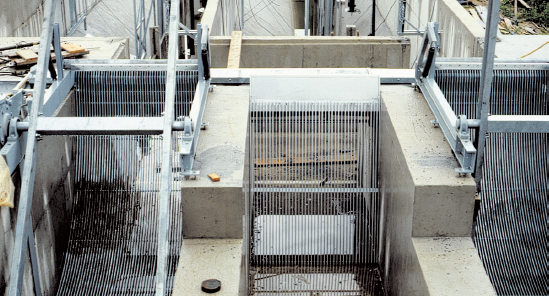
Bar screens are mechanical filtration devices employed in wastewater treatment facilities to remove large solid material from wastewater flows. They are typically the first line of defense in a treatment plant, capturing items such as rags, sticks, plastics, and other large debris that could potentially damage downstream equipment, clog systems, or disrupt biological processes. Bar screens consist of parallel steel bars or rods spaced at defined intervals — the bar spacing (or clear opening) is the primary design parameter that determines which solids are captured and which pass through to downstream treatment.
The Importance of Bar Screens in Wastewater Treatment
Protecting Downstream Equipment
The primary function of bar screens is to protect subsequent treatment processes and equipment from damage. By intercepting large debris, bar screens prevent clogs and mechanical failures in pumps, pipes, and finer filtration systems. This protection is critical to maintaining the operational integrity and efficiency of the entire treatment facility. A single rag bypassing the bar screen can wrap around a pump impeller within minutes, requiring an unplanned shutdown for manual clearing — an event that bar screens prevent hundreds of times per day at large facilities.
Enhancing Treatment Efficiency
By removing large solids early in the treatment process, bar screens help enhance the overall efficiency of the wastewater treatment plant. Reducing the solids load on secondary treatment processes allows biological systems to operate more efficiently, effectively, and without excessive wear. Rags and fibrous materials that bypass bar screens accumulate in aeration tanks and bioreactors, reducing effective treatment volume and creating operational challenges that are difficult and expensive to remediate.
Regulatory Compliance
Meeting regulatory standards is a significant concern for wastewater treatment facilities. Bar screens play an essential role in ensuring that wastewater discharge meets environmental regulations by preventing large pollutants from entering natural water bodies. The EPA 40 CFR Part 133 secondary treatment regulations and most NPDES permits require functioning preliminary treatment — including screening — as a prerequisite for compliance.
Design and Operation of Bar Screens
Basic Components
The fundamental components of a bar screens in wastewater treatment system include the parallel bars that create a grid to intercept debris, a sturdy frame typically made of stainless steel (Type 304 or 316L depending on corrosion exposure), a cleaning mechanism (rake, brush, or hydraulic system), a screenings collection and conveyor system, and controls and instrumentation for automated operation. The bar spacing, frame geometry, and cleaning system type are jointly specified to match the flow conditions, debris characteristics, and reliability requirements of the specific installation.
Bar screens are categorized based on the spacing of the bars. Coarse screens have larger openings (25 mm or greater) and capture bigger debris, while fine screens have smaller openings (3–15 mm) to intercept finer solids. Medium bar screens (10–25 mm) occupy the intermediate range and are the most common configuration at municipal wastewater treatment plants.
Installation and Placement
Bar screens are installed in the influent channels of wastewater treatment plants. Their placement ensures that large solids are removed from the wastewater flow early in the process. Bar screens can be installed at an angle (typically 45–80° from horizontal) to facilitate gravity-assisted cleaning and debris removal, or vertically in installations where mechanical cleaning systems operate on a vertical track.
The influent channel must be sized to maintain adequate approach velocity (typically 0.45–0.9 m/s at average flow) to prevent grit and heavy solids from settling upstream of the screen, while not exceeding the velocity at which debris is carried through rather than captured. Channel width, depth, and number of parallel screens are determined by peak flow rate with one screen out of service for maintenance — the N−1 design criterion that ensures uninterrupted screening during maintenance events.
Mechanisms of Operation
Manual screens require periodic manual cleaning by operators using rakes or other equipment, and are appropriate only for smaller facilities (typically below 1,000 m³/day) or as emergency bypass screens at larger plants. Mechanical screens at larger or more advanced facilities include automated cleaning mechanisms — rakes, brushes, or hydraulic systems — that remove captured debris continuously or at set intervals based on headloss differential across the screen. Cleaned screenings are typically conveyed to a compactor and washer that reduces volume and odor before disposal in a lined dumpster or landfill.
Types of Bar Screens
Coarse Bar Screens
Coarse bar screens are the first line of defense and are designed to intercept large debris. They typically have bar spacings of 25 mm (1 inch) or greater, and are positioned upstream of pumping stations or primary clarifiers to prevent large objects from entering the plant. These screens are crucial for preventing significant blockages and protecting the initial stages of the treatment process.
Fine Bar Screens
Fine bar screens come into play after the coarse screens and have much smaller bar spacings, often in the range of 5–15 mm. These screens capture smaller solids that passed through the coarse screens, providing more refined filtration before secondary treatment processes. Fine bar screens at municipal plants typically produce screenings volumes of 0.005–0.03 m³ per 1,000 m³ of wastewater treated.
Inclined Bar Screens
Inclined bar screens are mounted at an angle, usually between 30–45 degrees from the vertical. This design facilitates gravity-assisted cleaning as debris slides down the screen and is easier to remove. The angle also helps maintain a constant water flow velocity across the screen surface.
Vertical Bar Screens
Vertical bar screens are set up straight within the influent channel. They are used in facilities with specific space constraints or design requirements and require mechanical assistance for cleaning due to the vertical orientation of the bars.
Curved Bar Screens
Curved bar screens feature a concave or convex design, enabling more compact installation and enhanced debris capture. This design can improve the efficiency of the screening process and is useful in facilities with limited space or unusual channel geometries.
Subtopic Overview: Bar Screen Technologies
Bar screen technology encompasses not just the basic parallel-bar screen configuration but a range of mechanized, specialized, and enhanced screening systems that address specific flow conditions, debris characteristics, and performance requirements. The subtopics below cover the three primary bar screen technology categories addressed in depth on this site.
Bar Screens in Wastewater Treatment: Essentials for Efficient Solids Removal
The foundational principles governing bar screens in wastewater treatment performance — approach velocity, headloss, cleaning frequency, and screenings handling — are what determine whether a bar screen installation reliably protects downstream equipment or becomes a recurring maintenance liability that operators work around rather than rely on. Approach velocity in the influent channel must be maintained above 0.45 m/s at minimum flow to prevent grit and heavy solids from settling in the channel upstream of the screen, and below 0.9 m/s at peak flow to prevent light debris from being swept through the bar openings rather than being captured — designing the channel cross-section to maintain velocity within this range across the full flow range from minimum dry weather flow to peak wet weather flow is a fundamental hydraulic design requirement. Headloss across a clean bar screen is typically 25–75 mm at design flow; as debris accumulates, headloss increases progressively until the cleaning mechanism activates. Cleaning systems are typically triggered by headloss differential sensors that activate the rake or brush when headloss reaches a set threshold (typically 150–300 mm), ensuring that cleaning frequency automatically adjusts to the actual debris load rather than operating on a fixed time cycle that would under-clean during heavy load events and waste energy during light load periods.
Mechanical Bar Screen
A mechanical bar screen replaces the manual raking operations of simple inclined screens with automated cleaning mechanisms — most commonly a reciprocating rake system that travels the length of the screen bars, engaging the debris with comb teeth that lift it to a discharge point at the top of the screen where it falls onto a conveyor or into a collection hopper. Front-cleaned mechanical bar screens position the rake on the upstream (flow-approach) face of the screen bars, while back-cleaned designs position it on the downstream face — front-cleaned designs provide more aggressive debris removal and handle larger, more tangled materials more reliably, while back-cleaned designs have a simpler structural arrangement that may be preferred in narrower channel installations. Traveling band screens — a variant of the mechanical screen concept using a continuous perforated band rather than fixed bars — provide very high capture efficiency for fine solids (down to 1–2 mm opening) and are increasingly specified at facilities converting from primary treatment to direct secondary treatment configurations where finer preliminary screening reduces the organic loading on downstream membrane bioreactors. The motorized drive system (typically 0.37–2.2 kW depending on screen width and debris load), control panel with headloss-based automation, and screenings washer-compactor unit are the key auxiliary components that must be specified alongside the screen itself for a complete mechanical bar screen installation.
Bar Screen Wastewater Treatment: Selection and Specification
Bar screen wastewater treatment selection and specification requires systematic evaluation of the plant’s hydraulic loading profile, debris characteristics, channel geometry, redundancy requirements, and site-specific constraints — a multi-parameter decision process where selecting the wrong screen type for the application results in either chronic operational problems (undersized or inappropriate cleaning mechanism) or unnecessarily high capital and operating cost (oversized or over-featured system). The hydraulic design basis begins with the peak wet-weather flow (PWWF) — typically 3–5× average dry weather flow (ADWF) at combined sewer systems — with the screen channel and cleaning mechanism sized to handle PWWF with N−1 redundancy, meaning one screen channel can be isolated for maintenance while the remaining channel(s) handle full PWWF. Bar spacing selection depends on what downstream equipment must be protected: for facilities with fine bubble diffusers and membrane bioreactors, 3–6 mm clear opening is increasingly specified to prevent rag accumulation on membranes and diffuser fouling; for conventional activated sludge with coarse bubble aeration, 10–25 mm clear opening is typical; for headworks preceding pumping stations only, 25–50 mm coarse screens may be sufficient. Materials specification for bar screens must account for the corrosive environment — Type 316L stainless steel is the standard for bars, frames, and rakes in municipal wastewater, while duplex stainless steel (2205) or high-density polyethylene frames are specified for industrial applications with elevated sulfide, chloride, or acid concentrations that would accelerate corrosion of standard 316L.
Comparison of Bar Screen Types for Wastewater Applications
| Screen Type | Bar/Opening Size | Cleaning Method | Solids Captured | Best-Fit Applications | Key Limitations | Relative Capital Cost |
|---|---|---|---|---|---|---|
| Coarse Manual Bar Screen | 25–100 mm | Manual raking by operators | Large rags, debris, plastics | Small plants (<1,000 m³/d); emergency bypass; upstream of pumping stations | Labor-intensive; not suitable for unattended operation; high PWWF not manageable manually | Very Low |
| Inclined Mechanical Bar Screen | 10–50 mm | Automated reciprocating rake; headloss-triggered | Coarse rags, solids, large debris | Medium municipal plants; combined sewer overflows; primary headworks protection | Limited to larger bar spacings; less effective for fibrous materials than front-cleaned designs | Low–Medium |
| Front-Cleaned Mechanical Bar Screen | 6–25 mm | Front rake traveling full bar length; automated | Rags, fibrous materials, medium solids | Large municipal plants; combined sewer; facilities with high rag loads | Higher capital than back-cleaned; rake engagement with bars requires precise alignment | Medium |
| Back-Cleaned Mechanical Bar Screen | 6–25 mm | Downstream rake; automated | Medium solids; less effective for tangled rags | Moderate debris loads; space-constrained headworks; separated sewer systems | Less effective for tangled rags than front-cleaned; screenings may fall back through bars | Medium |
| Fine Mechanical Bar Screen | 3–6 mm | Automated brush or rake; continuous or interval | Fine solids, small rags, fibrous material | MBR pre-treatment; water reuse applications; facilities eliminating primary clarifiers | Higher screenings volume; more frequent cleaning; more sensitive to grit damage | Medium–High |
| Traveling Band Screen | 1–6 mm | Continuous band movement; spray wash cleaning | Very fine solids; nearly all suspended debris | Tertiary screening for reuse; cooling water intake; high-quality preliminary treatment | Highest capital cost; requires spray wash system; sensitive to grit and abrasive solids | High |
Challenges and Maintenance of Bar Screens
Common Challenges
Debris Accumulation: Over time, debris can accumulate on the screen bars, reducing effectiveness and increasing the risk of bypassed flow. Automated cleaning systems triggered by headloss differential address this systematically, but power outages, rake jams, and control failures can allow accumulation to reach bypass levels.
Mechanical Failures: The mechanical components of automatic bar screens — motors, rakes, and brushes — can fail due to constant exposure to harsh environmental conditions or poor maintenance. Rake jam sensors and mechanical shear pins that protect the drive mechanism from overload are standard protective features on modern screens.
Corrosion: Corrosion is a persistent issue in the wet and chemically aggressive environment of wastewater treatment plants. Specifying Type 316L stainless steel or duplex stainless for all wetted components, combined with periodic inspection and protective coating touch-up, is essential to achieve the expected 20–25 year design life.
Power Supply Issues: Mechanical bar screens rely on a steady power supply. Emergency bypass channels with manually cleaned coarse screens provide operational continuity during power interruptions.
Maintenance Practices
Routine inspection of bar screens and associated components is crucial — identifying wear, corrosion, or misalignment before failure reduces unplanned downtime. Periodic manual or automated cleaning prevents debris buildup. For mechanical bar screens, keeping moving parts well-lubricated reduces friction and wear. Timely replacement of worn-out parts — rakes, brushes, motors, and bars — is necessary to maintain functionality. Most manufacturers recommend annual major overhaul inspections for high-duty continuous-operation mechanical screens.
Monitoring and Control Systems
Advanced wastewater treatment facilities employ monitoring and control systems to enhance the efficiency and reliability of bar screens. These systems provide real-time data on screen performance, trigger automatic cleaning cycles based on headloss differential across the screen, and alert operators to malfunctions or maintenance needs, ensuring consistent operation with minimal manual intervention.
Field Notes: Practical Guidance for Bar Screen Design and Operation
Specifying Bar Spacing for MBR Pre-Treatment
The most consequential specification decision for bar screens at facilities planning membrane bioreactor secondary treatment is bar spacing — and the industry has converged on 3–6 mm clear opening as the standard for MBR pre-treatment, based on extensive operational experience showing that coarser pre-screening allows fibrous materials and rags to accumulate on membrane surfaces, reducing flux and requiring more frequent chemical cleaning. At plants converting from conventional activated sludge (with 6–10 mm bar screens) to MBR configuration, upgrading the preliminary screening to 3 mm at the same time as the MBR installation is mandatory, not optional — the MBR membrane bundle will reveal every gap in preliminary screening within weeks of startup. For broader context on how bar screens compare with other screening equipment types used in wastewater treatment headworks, the General Screening resource covers the full screening equipment selection framework including coarse, fine, microscreens, and drum screens. The Fine Screen resource addresses 1–6 mm opening screening equipment in detail, including perforated plate, step screen, and band screen configurations that compete with fine bar screens for the preliminary treatment role at MBR and water reuse facilities. For applications where a rotating drum configuration is under consideration alongside bar screens, Drum Screen covers the externally-fed rotary drum screen design, which offers higher solids capture rates and lower headloss than equivalent-aperture bar screens for some debris compositions.
Common Design and Specification Mistakes
The most frequent bar screen design error is sizing the screen channel and selection width based on average daily flow rather than peak wet weather flow with N−1 redundancy. A bar screen that handles ADWF adequately but submerges or bypasses during a 2-year storm event is a permit compliance risk every time it rains. A second common mistake is specifying a screenings washer-compactor as an optional component to reduce initial capital cost — uncompacted, unwashed screenings retain 75–80% moisture content and significant putrescible organic matter, creating odor problems at the collection point and increasing disposal cost and weight substantially. The compactor reduces screenings volume by 40–60% and moisture content to below 60%, with a payback period typically below 18 months in avoided disposal costs alone.
The Future of Bar Screens: Technological Advancements
Smart Bar Screens: Integration of sensors and IoT-enabled devices enables continuous monitoring of screen performance, predictive maintenance scheduling, and detailed operational data transmission to SCADA systems. These systems can automatically adjust cleaning cycle frequency based on real-time debris load without operator intervention.
Enhanced Materials and Coatings: Innovations in materials science have led to enhanced materials and coatings that improve durability and corrosion resistance of bar screens, reducing maintenance costs and extending design life.
Hybrid Screening Systems: Hybrid screening systems combine features of traditional bar screens with additional filtration technologies such as micro-screens or drum screens, offering improved efficiency and the ability to handle a broader range of solid sizes.
Energy-Efficient Designs: Newer bar screen designs prioritize energy efficiency, incorporating low-power motors, optimized mechanical operations, and variable frequency drives that reduce energy consumption during low-flow periods.
Modular and Customizable Bar Screens: Modular designs allow easy expansion, upgrades, or adjustments to meet specific facility requirements and changing operational needs without full replacement.
Case Studies: Implementation of Bar Screens in Various Facilities
Urban Wastewater Treatment Plant
An urban wastewater treatment plant serving a metropolitan area upgraded its aging manual bar screens to automated mechanical screens equipped with smart sensors and automatic cleaning mechanisms. The new system significantly reduced manual labor and maintenance costs, while the facility reported fewer operational disruptions and improved treatment efficiency — highlighting the benefits of modern bar screen technology in high-load urban environments.
Industrial Wastewater Treatment Facility
An industrial facility dealing with high volumes of wastewater containing large solid particles implemented a combination of coarse and fine bar screens. The coarse screens captured the bulk of the large debris, while the fine screens provided additional filtration. This two-tier screening approach protected the facility’s sensitive downstream equipment and ensured compliance with stringent environmental regulations.
Small Community Wastewater Treatment Plant
A small community wastewater treatment plant faced frequent clogs and mechanical failures in its existing bar screens. By switching to inclined bar screens with enhanced corrosion-resistant materials, the plant improved its debris removal efficiency and reduced maintenance downtime — demonstrating the importance of selecting the right bar screen design for specific facility needs and debris characteristics.
Conclusion
Key Takeaways
- Bar screens are the first line of defense in wastewater treatment and must be sized for peak wet weather flow with N−1 redundancy — a screen that handles average flow but bypasses during storm events creates permit compliance risk precisely when combined sewer overflow loads are highest and environmental protection is most critical.
- Bar spacing selection is the primary performance-determining specification — 3–6 mm clear opening is the standard for MBR pre-treatment; 6–10 mm for conventional activated sludge; 25+ mm for upstream-of-pumping-station coarse protection; specifying coarser than needed for the downstream process leads to chronic rag accumulation problems that are expensive to diagnose and remediate.
- Front-cleaned mechanical designs outperform back-cleaned for high-rag-load combined sewer applications — the aggressive rake engagement with the bar face from the upstream side provides more reliable rag removal for tangled fibrous materials than the gentler downstream-side cleaning approach, at modestly higher capital cost.
- Screenings washer-compactors should be specified as standard, not optional — the reduction in disposal volume (40–60%), moisture content, and odor typically yields payback below 18 months in avoided hauling and disposal costs, and the operational improvement in handling dry compacted screenings versus wet raw screenings is significant for plant staff.
- Headloss differential-based cleaning control is superior to time-based cleaning cycles — differential pressure triggers that activate the rake only when headloss exceeds a threshold automatically adapt cleaning frequency to actual debris load, reducing energy consumption during light load periods and preventing rag buildup during high-load events without operator intervention.