
Centrifugal Pumps Clogging and Ragging: How to Reduce Blockages
Centrifugal Pumps Clogging and Ragging: How to Reduce Blockages
Introduction
The modern wastewater stream has changed radically over the last two decades. The proliferation of non-dispersible synthetic fabrics — commonly marketed as flushable wipes — combined with water conservation measures that reduce transport velocities has created a difficult operating environment. For engineers involved in lift station design and plant operations, clogging and ragging has shifted from a nuisance to a primary operational expense and a reliability risk.
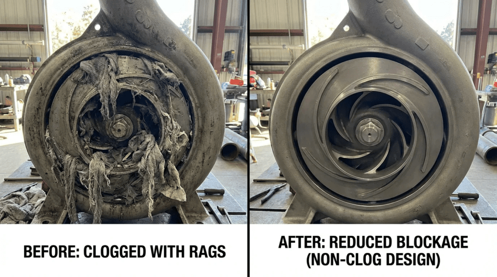
Reactive maintenance costs associated with unclogging pumps have risen substantially in many municipalities over the past fifteen years, though the increase varies widely by service area and influent composition. Deragging is not merely labor-intensive; it presents real safety hazards to operators who must physically access volutes or open check valves to clear obstructions. A common misconception is that increasing a pump’s sphere-passing capability suffices for modern solids. Fibrous material does not behave like spherical solids — it forms ropes and mats that catch on the leading edges of vanes, reducing efficiency and eventually tripping motors on overload.
Centrifugal pumps remain the workhorse of water and wastewater transport for their hydraulic versatility and relatively low capital cost. But their application in raw wastewater, sludge recirculation and influent headworks requires a nuanced approach to selection. Standard enclosed impellers, once the industry default, increasingly fail in high-rag environments. Broader supplier positioning is covered in our overview of the top centrifugal pump manufacturers for water and wastewater.
How to Select and Specify
The selection process must prioritize the specific nature of the solids over pure hydraulic efficiency. Selecting the most efficient pump at the duty point often means selecting an impeller geometry prone to catching fibers.
Duty Conditions & Operating Envelope
The relationship between operating point and best efficiency point is critical for solids handling. When a pump operates significantly to the left of best efficiency at low flow, recirculation eddies form at the suction eye and the discharge cutwater. Those eddies act as spinning looms, twisting loose fibers into tight ropes before they even enter the impeller vane.
- Continuous against intermittent: In lift stations with long retention times, solids settle and mat together. When the pump starts it faces a slug of high-concentration solids, so pumps for this service require higher starting torque and the capability to process that initial load.
- Variable frequency drives: Drives save energy, but running a pump too slowly reduces fluid velocity through the volute. That reduced velocity may fail to flush solids through the discharge, leading to accumulation. Specifications should define a minimum scouring speed rather than just a minimum hydraulic flow.
- Future capacity: Oversizing pumps for twenty-year growth horizons is a leading cause of ragging. An oversized pump runs far to the left of its curve during early years, maximizing recirculation and rag ball formation. Drives or smaller trim impellers during the initial years are essential.
Materials & Compatibility
Where the strategy involves chopping or shearing solids, standard grey cast iron is often insufficient for the cutting elements. The interaction between cutting edges and inorganic grit — sand, road salts — found in combined sewers rapidly dulls standard materials.
- Cutting elements: Specify high-chrome iron or hardened stainless steel such as 440C or 17-4PH, heat treated to a hardness in the mid-to-high 50s Rockwell C, for chopper bars, cutter plates and impeller leading edges.
- Volute materials: The volute can remain cast iron, but the wear plate or suction cover where close-tolerance shearing occurs must be hardened to maintain the tight clearances needed for effective solids destruction.
- Clearance maintenance: Material selection must account for the ability to adjust clearances. As materials wear the gap opens, and stringy material begins folding over the cutter rather than shearing.
Hydraulics & Process Performance
Impeller geometry is the single most influential factor in reducing blockages.
- Leading edge geometry: Backswept leading edges let rags slide off rather than staple to the vane. A purely radial leading edge is a catch point.
- Throughlet size: The three-inch spherical solid standard is a baseline, but for ragging the cross-sectional area of the channel matters less than the absence of catch points. A larger passage with a sharp cutwater tongue can clog faster than a smaller passage with a smooth, contoured volute.
- Cavitation: Cavitation pits the impeller surface, and those pits become anchor points for rags. Maintaining adequate suction head margin keeps surfaces smooth.
Installation Environment & Constructability
Sump design dictates how solids enter the pump. A poorly designed wet well creates floating mats of grease and rags.
- Floor slope: Flat-bottom wet wells encourage deposition. Fillets and steeply sloped floors direct solids toward the pump suction.
- Suction velocity: Too low and solids settle in the pipe; too high and vortices form. Designing for roughly 3 to 5 ft/s in the suction piping keeps solids suspended without excessive friction loss.
- Guide rails: For submersible pumps, the discharge sealing flange must be robust. Leakage at that connection causes local recirculation that attracts rags to the guide rail system, eventually binding the pump during removal.
Reliability, Redundancy & Failure Modes
In high-ragging applications, mean time between failure is dictated by clogging frequency rather than mechanical bearing or seal failure.
- Derating factors: When selecting chopper or grinder pumps, apply a motor service factor. Chopping a heavy rag ball causes momentary torque spikes, and standard motors may trip on overload or overheat.
- Redundancy: N+1 is standard in critical lift stations subject to heavy ragging. Consider a jockey arrangement where a smaller solids-handling pump handles dry weather flow at higher velocity while larger pumps engage only during storm events.
Controls & Automation
Modern mitigation relies heavily on monitoring rather than mechanical brute force.
- Power monitoring: Traditional thermal overloads are too slow. Power monitors measure instantaneous shaft power, and a characteristically jagged power signature often precedes a full clog.
- Auto-reverse: Specifications should require drives or soft starters capable of pump cleaning cycles. On detecting a torque spike or current increase, the pump stops, reverses rotation briefly to dislodge the obstruction, then resumes forward operation.
- SCADA integration: The system should log cleaning events. A sudden spike in event frequency indicates a change in influent composition or a mechanical issue such as worn cutter clearance.
Maintainability, Safety & Access
- External adjustment: For pumps with cutting faces, specify mechanisms allowing clearance adjustment from outside the pump without full disassembly.
- Clean-out ports: Dry-pit pumps should feature hand-hole cleanouts on the suction elbow or volute, allowing operators to remove blockages without decoupling piping.
- Lifting apparatus: Ensure permanent davit cranes or hoists are rated not just for pump weight but for the breakout force required to lift a pump silted in or bound by rags.
Lifecycle Cost Drivers
Chopper pumps generally have lower hydraulic efficiency than standard non-clog pumps. The energy penalty is usually negligible compared with the cost of a vacuum truck call-out or overtime labor to unclog a pump. Budget for replacement cutting elements on a multi-year cycle depending on grit load.
Comparison Tables
| Technology | Primary Mechanism | Best-Fit Application | Considerations | Maintenance Profile |
|---|---|---|---|---|
| Semi-open with relief groove | Leading edge sweeps solids away; a relief groove in the volute lets trapped solids recirculate and exit | Raw sewage, stormwater, general lift stations | Can clog where solids are exceptionally long or strong. Requires precise clearance setting. | Wear plate clearance adjustment required to maintain efficiency |
| Chopper or cutter | Rotating blades actively slice solids against a stationary anvil or plate before the impeller | Institutional facilities, lift stations with heavy wipe loading | Lower hydraulic efficiency. Higher suction head required. Cutting edges dull over time in gritty service. | Periodic sharpening or replacement of cutter bars and blades |
| Vortex or recessed | Impeller recessed in the volute creates a fluid vortex; only a small fraction of solids contact the impeller | Sludge, grit, high concentrations of stringy material | Low hydraulic efficiency, commonly in the 35 to 55 percent range. Can generate significant vibration if operated far from best efficiency. | Very low. Impeller wear is minimal since it avoids contact. |
| Screw centrifugal | Single spiral vane with a long sweeping motion. Gentle handling with large free passage. | Return and waste sludge pumping, shear-sensitive sludge, heavy ragging | Steep head-capacity curve. Large physical footprint. Sensitive to suction conditions. | Liner adjustment required. Leading edge repair if damaged by tramp metal. |
| Enclosed non-clog | Standard two or three vane enclosed impeller with wide channels | Clean water, effluent, stormwater with minimal debris | Not recommended for raw sewage containing wipes. Prone to leading-edge stapling and rag ball formation. | Standard wear ring replacement. High risk of clogging interventions. |
| Application | Flow Range | Risk Level | Recommended Technology | Key Constraint |
|---|---|---|---|---|
| Small neighborhood lift station | Low | High — low velocity, high wipe ratio | Chopper pump, or grinder at the smallest flows | Preventing matting in the wet well |
| Large regional lift station | High | Medium — high velocity aids passage | Semi-open with relief groove, or screw centrifugal | Energy efficiency becomes a major cost driver |
| Sludge recirculation | Moderate | High — concentrated solids | Screw centrifugal or vortex | Protecting floc structure at low shear against passing rags |
| Institutional service | Low to moderate | Extreme — bedding, clothing, plastics | Heavy duty hardened chopper | Requires aggressive cutting; efficiency is secondary |
| Stormwater runoff | Very high | Low — mostly inorganic debris | Axial or mixed flow | Screening ahead of the pump is usually required |
Engineer & Operator Field Notes
Commissioning & Acceptance Testing
Factory testing confirms hydraulic performance. Site testing is where solids handling capability is verified.
- Vibration baseline: Establish a baseline with clean water, then monitor vibration as solids are introduced. A significant immediate rise suggests the impeller is unbalanced by rag accumulation.
- Current draw verification: Verify amperage during first storm flows or a ragging simulation. Ensure overload protection is set high enough to accommodate the torque spikes of cutting but low enough to protect the windings.
- Deragging function test: If drives with anti-clogging logic are installed, test them. Manually trigger the logic to confirm the pump stops, reverses and ramps back up without inducing water hammer in the discharge force main.
Common Specification Mistakes
The most frequent error is copying older non-clog specifications forward without updating them.
- The non-clog misnomer: Standard specifications often ask for non-clog pumps capable of passing a three-inch sphere. That metric is dated. A modern specification should define solids handling capability with respect to fibrous material, potentially referencing specific impeller designs such as semi-open backswept with relief groove, or chopper type.
- Oversizing motors: Torque is needed, but grossly oversizing motors increases inrush current and requires larger electrical gear. It also forces the pump to run at partial load where power factor is poor. Match motor torque to the inertia of the impeller and the cutting load.
- Ignoring minimum flow: Specifying a drive range from zero to full speed is a design error. Minimum flow must be calculated from the minimum scouring velocity in the rising main — commonly around 2 ft/s. Running below that guarantees solids deposition in the pipe, which eventually falls back onto the pump check valve.
O&M Burden & Strategy
Operational strategy shifts from reactive unclogging to preventive monitoring.
- Daily and weekly: Monitor trends for gradual current creep. A slow rise in amps at the same flow rate indicates partial blockage or rag buildup on the leading edge.
- Monthly: Check the cutting gap on chopper pumps. As the gap increases, the pump loses the ability to scissor-cut and rags begin folding and jamming.
- Quarterly: Inspect check valves. Rags passing through the pump often hang up on the flapper or seat, and a partially open check valve causes backflow and pump spinning, leading to startup failures.
- Predictive: Use vibration analysis to detect imbalance caused by uneven rag loading on the impeller.
Troubleshooting
- High amps, low flow. Partial blockage in the volute or impeller vane. Trigger a reverse cycle; if unsuccessful, mechanical removal is required. Check suction wear plate clearance.
- Heavy vibration at start that then smooths out. A rag ball resting in the suction was ingested at start and eventually passed. Investigate wet well cleaning cycles, since the pump is ingesting settled solids.
- Frequent tripping on overload. Solids load exceeds motor torque with the chopper jammed, or the motor service factor is too low. Check for inorganic debris jamming the cutter and verify thermal overload settings.
Design Details and Calculations
Sizing Methodology
Velocity governs. In clean water you design for efficiency. In wastewater you design for transport. Maintain a minimum of roughly 2 ft/s in discharge piping, preferring 3 to 5 ft/s in the immediate pump vicinity to ensure scouring. Velocity in ft/s equals 0.4085 multiplied by flow in gpm, divided by the square of the pipe inside diameter in inches.
The force main profile. Analyze the system curve. Where static head is high and friction head low, the pump operates in a narrow flow range. If the pump drifts left to low flow because head increased — a partially blocked force main, for instance — velocity drops and ragging accelerates. That is a self-reinforcing failure mode worth designing against.
Specification Checklist
- Impeller hardness: “Impeller and cutting elements shall be heat-treated to a stated minimum Rockwell C hardness.”
- Relief features: “Impeller or volute shall feature a self-cleaning groove or relief path to discharge solids trapped between the wear plate and impeller vane.”
- Passage guarantee: “Pump shall be capable of passing a solid of stated size, or chopping a solid of that size into slurry.”
- Testing standard: Performance testing per the applicable Hydraulic Institute standard for the pump type.
- Cable entry: “Cable entry shall feature a longitudinal seal to prevent capillary migration of water into the motor in the event of cable sheath damage.” This matters because ragging frequently leads to cable tension and damage.
Standards
- Hydraulic Institute standards: Governing nomenclature and design for centrifugal pumps, and the applicable testing standard for submersible units
- Hydraulic Institute suction head margin guidance: Critical to preventing the cavitation-induced surface roughness that catches rags
- AWWA C500 series: Relevant for check valves, which must also be clog-resistant — swing checks with external levers outperform wafer checks in this service
- NEC Article 430: Motors and motor circuits. Size disconnects and overloads for the high-torque events characteristic of chopping pumps.
Frequently Asked Questions
What is ragging in centrifugal pumps?
Ragging is the accumulation of fibrous material — wipes, hair, rags, string — on the leading edges of pump impellers or within the volute. The fibers entangle and wrap around the impeller, forming ropes or balls. This reduces the cross-sectional area for flow, decreases hydraulic efficiency, increases vibration, and eventually causes the pump to bind or the motor to trip on overload.
What is the difference between a chopper pump and a grinder pump?
A grinder pump is typically a small, low-flow unit used in residential pressure sewer systems, macerating solids into a fine slurry with a high-speed cutting mechanism before the fluid reaches the impeller. A chopper pump is a larger municipal or industrial unit using a sharpened impeller and cutter bar to slice solids, designed for higher flows and general lift station duty. Grinders serve point-of-source applications; choppers serve collection system duty.
Do variable frequency drives reduce clogging?
They can, if programmed with deragging or pump cleaning algorithms that detect torque spikes and reverse the pump to unravel fibers. But simply using a drive to slow a pump for energy savings can increase clogging if velocity drops below the scouring threshold, allowing solids to settle and mat.
Why do non-clog pumps still clog?
Non-clog is an industry classification referring to the ability to pass a sphere of a certain size, not a guarantee. Traditional enclosed non-clog impellers were designed for organic solids, not the high-tensile synthetic fibers in modern wipes. Those fibers staple onto vane leading edges where a spherical solid would pass through unimpeded.
How often should chopper pumps be maintained?
Inspect cutting clearances every six to twelve months depending on grit load. Once the clearance between impeller and cutter plate widens beyond the manufacturer’s limit, cutting action degrades and ragging resumes. In high-sand environments, cutter components may need replacement on a multi-year cycle.
What is the cost difference between a standard pump and a chopper pump?
A chopper pump typically costs substantially more than a standard cast-iron non-clog pump of the same hydraulic duty, driven by hardened materials, precision machining of cutting faces and more robust mechanical seals. Return on that premium is often rapid where the standard pump requires frequent vacuum truck cleaning or manual deragging.
Related Topics
Readers working through centrifugal pump selection and operation more broadly will find useful material in our centrifugal pump frequently asked questions, which covers hydraulics, curve reading and common operational issues across applications.
Conclusion
Key Takeaways
- Redefine non-clog: Sphere-passing capability is no longer the defining metric. Look for backswept leading edges, relief grooves or active cutting mechanisms.
- Velocity is critical: Do not operate pumps below minimum scouring velocity via drives. Low velocity encourages rag ball formation in the suction.
- Material matters: For cutting applications, specify heat-treated components to a stated hardness to withstand the abrasion and corrosion cycle.
- Smart controls: Use drives with power-based monitoring and auto-reverse logic to clear incipient clogs before they bind the pump.
- Correct sizing: Avoid massive oversizing. A pump operating far left of best efficiency generates recirculation eddies that weave rags into ropes.
Addressing clogging and ragging requires a departure from clean-water hydraulic thinking. The pump must be viewed as a solids-processing device rather than a machine for moving liquid. The shift in waste stream composition has permanently altered the physics of wastewater transport, requiring specialized hydraulics and hardened materials.
Successful specifications balance hydraulic efficiency against operational reliability. While a chopper pump consumes somewhat more electricity than a standard enclosed impeller pump, eliminating weekly maintenance call-outs and reducing operator safety risk provides a decisive advantage in total cost of ownership. Robust site design, appropriate material selection and intelligent control strategies together produce lift stations that stay reliable in the face of modern waste streams.