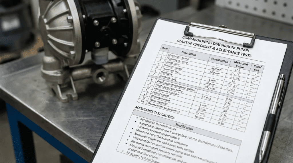
Commissioning Diaphragm: Startup Checklist and Acceptance Tests
Introduction
The failure of a chemical feed system or sludge transfer unit in a water treatment plant often isn’t caused by a defective pump; it is caused by a failure in the commissioning process. In municipal and industrial applications, up to 60% of early-life equipment failures can be traced back to improper installation, inadequate pipe stress relief, or ignoring hydraulic acceleration head requirements during startup. When engineers overlook the specific requirements for Commissioning Diaphragm: Startup Checklist and Acceptance Tests, the result is often diaphragm rupture, piping fatigue, or inaccurate chemical dosing that compromises regulatory compliance.
Diaphragm technology—encompassing Air-Operated Double Diaphragm (AODD) pumps, mechanical metering pumps, and hydraulic actuation systems—is ubiquitous in water and wastewater treatment. These units handle aggressive chemicals like Sodium Hypochlorite, viscous polymers, and abrasive lime slurries. Unlike centrifugal pumps, diaphragm pumps are positive displacement machines that create unique hydraulic pulses. Consequently, their startup procedures require strict attention to ancillary equipment, such as backpressure valves, pulsation dampeners, and pressure relief valves (PRVs).
Improper specification or a rushed Site Acceptance Test (SAT) can lead to vapor locking, loss of prime, or catastrophic over-pressurization. This article provides a rigorous technical framework for engineers and operators to ensure these critical systems are specified correctly and commissioned for long-term reliability.
How to Select / Specify for Successful Commissioning
Successful commissioning begins during the design phase. If the equipment specified does not match the hydraulic reality of the piping system, no amount of onsite tuning will correct the issue. The following criteria must be defined to ensure the equipment can pass the Commissioning Diaphragm: Startup Checklist and Acceptance Tests.
Duty Conditions & Operating Envelope
Defining the operating envelope for diaphragm pumps requires more than just a single flow and head point. Because these pumps pulse, the peak instantaneous flow is higher than the average flow, which dictates friction loss calculations.
- Turndown Ratio: Specify the required accuracy across the entire range. A 100:1 turndown ratio is common for modern stepper-motor diaphragm pumps, while older mechanical designs may only offer 10:1.
- Acceleration Head: Unlike continuous flow, reciprocating diaphragms must accelerate the fluid column with every stroke. Engineers must calculate the inlet pressure required to overcome this inertia (NPSHa) to prevent cavitation and knocking.
- Viscosity Variations: For polymer or sludge applications, define viscosity at the minimum ambient temperature. High viscosity delays check valve seating, reducing volumetric efficiency.
Materials & Compatibility
Material selection is critical for the diaphragm—the flexing component that separates the process fluid from the drive mechanism. Premature failure here is the most common operational headache.
- Diaphragm Composition: PTFE (Teflon) offers the best chemical resistance but limited flexibility. EPDM or Viton are more flexible but have specific chemical limitations. Composite diaphragms (PTFE-faced EPDM) often provide the best balance.
- Check Valve Balls and Seats: These must be harder than the diaphragm material. Ceramic balls are preferred for aggressive chemicals like Ferric Chloride, while Stainless Steel is standard for non-corrosive sludges.
- Fluid Temperature: High temperatures reduce the pressure rating of plastic pump heads (PVDF, PVC). Specifications must account for the derating curve of the material.
Hydraulics & Process Performance
The interaction between the pump and the system piping determines performance. A diaphragm pump is a “flow generator,” not a pressure generator; it will build pressure until the fluid moves, the pipe bursts, or the motor stalls.
- System Curve vs. Relief Valve: The pump’s internal relief valve (for hydraulic diaphragms) or external PRV must be set 10-15% above the maximum system operating pressure, but below the piping’s pressure rating.
- NPSH Requirements: Net Positive Suction Head Required (NPSHr) for reciprocating pumps is typically higher than centrifugal pumps due to valve cracking pressure and acceleration losses.
- Flow Linearity: For metering applications, specify compliance with API 675 standards, which dictate linearity, steady-state accuracy, and repeatability (typically ±1%).
Installation Environment & Constructability
Physical installation constraints frequently hinder maintenance and commissioning.
- Flooded Suction: Whenever possible, design for flooded suction. While diaphragm pumps are self-priming, a flooded suction eliminates priming issues during startup and reduces the risk of dry-running.
- Maintenance Access: Ensure there is enough clearance to remove the pump head without dismantling the entire piping manifold. This is a common oversight in skid-mounted chemical feed systems.
- Piping Support: Pulsating flow creates vibration. Piping must be rigidly supported, but the connection to the pump should be flexible (using braided stainless steel or reinforced hose) to isolate pump vibration from the rigid piping.
Reliability, Redundancy & Failure Modes
Critical chemical feed systems (e.g., disinfection) require high reliability to avoid regulatory violations.
- Leak Detection: Specify double-diaphragm designs with an intermediate vacuum or pressure sensor. If the primary diaphragm fails, the sensor alerts the SCADA system while the secondary diaphragm contains the fluid, preventing a spill.
- Redundancy: A Duty/Standby (1+1) or Duty/Assist/Standby (2+1) configuration is standard. The standby pump should be exercised weekly to prevent check valves from sticking.
- Motor Protection: For motor-driven units, specify Totally Enclosed Fan Cooled (TEFC) or Washdown Duty motors if installed in corrosive environments.
Controls & Automation Interfaces
Modern diaphragm pumps are often “smart” devices.
- Signal Types: 4-20mA is standard for pacing flow. Pulse inputs are used for flow-proportional dosing. Profibus or Modbus integration allows for remote monitoring of stroke count, calculated flow, and error codes.
- Flow Verification: Do not rely solely on pump speed. Install a magnetic flow meter or thermal dispersion switch on the discharge side to verify actual chemical movement.
Maintainability, Safety & Access
Safety is paramount when dealing with pressurized chemicals.
- Pressure Relief: An external PRV is mandatory in the discharge piping, piped back to the supply tank (not the pump suction) to prevent heat buildup during dead-heading.
- Shielding: Spray shields should be installed over flanged connections on the discharge side of high-pressure chemical pumps.
Lifecycle Cost Drivers
- Reagent Savings: A highly accurate pump prevents chemical overdosing. Over a 20-year lifecycle, the cost of wasted chemical often exceeds the cost of the pump.
- Consumables: Analyze the cost and frequency of “wet end kits” (diaphragms, balls, seats, seals). Cheaper pumps often require more frequent and expensive rebuilds.
Comparison Tables
The following tables assist engineers in differentiating between common diaphragm pump technologies and determining the best fit for specific applications. Use Table 1 to select the technology and Table 2 to evaluate application suitability.
| Technology Type | Operating Principle | Primary Strengths | Limitations/Considerations | Typical Maintenance |
|---|---|---|---|---|
| Solenoid Driven Metering | Electromagnetic coil acts directly on the diaphragm shaft. | Low capital cost; high precision for low flows; compact footprint. | Limited pressure/flow capabilities; susceptible to overheating at high duty cycles; noisy “clacking” operation. | Diaphragm replacement every 6-12 months; check valve cleaning. |
| Motor-Driven Mechanical Diaphragm | Electric motor drives an eccentric cam to reciprocate the diaphragm. | Rugged; handles higher flows/pressures than solenoid; smoother flow profile. | Diaphragm is mechanically attached, creating stress points; higher repair cost than solenoid. | Oil changes (gearbox); diaphragm replacement annually. |
| Hydraulic Diaphragm | Plunger reciprocates oil, which flexes the diaphragm (hydraulically balanced). | Extremely high pressure capability; internal relief valve; longest diaphragm life (balanced pressure). | High capital cost; complex maintenance; oil contamination risk. | Hydraulic oil changes; filter replacement; rare diaphragm changes (2+ years). |
| AODD (Air Operated) | Compressed air shifts a spool valve, driving two diaphragms. | Can run dry indefinitely; handles solids/slurries; self-priming; shear-sensitive handling. | High energy cost (air consumption); pulsing flow requires dampeners; freezing exhaust in cold climates. | Air valve service; diaphragm/ball replacement; muffler cleaning. |
| Application Scenario | Best-Fit Technology | Critical Constraints | Operator Skill Impact | Relative CAPEX |
|---|---|---|---|---|
| Sodium Hypochlorite (Disinfection) | Motor-Driven or Smart Stepper | Off-gassing (vapor lock); corrosion; requires special venting valves. | Moderate (Requires calibration skill) | $$ – $$$ |
| Polymer Dosing (Coagulant) | Progressive Cavity (Rotary) or Large Diaphragm | Shear sensitivity (avoid high speed); high viscosity. | High (Polymer systems are complex) | $$$ |
| Lime Slurry | Peristaltic or AODD | Abrasion; settling solids; clogging of check valves. | Low to Moderate | $$ |
| General Sludge Transfer | AODD or Rotary Lobe | Large solids passage; variable flow requirements. | Low | $ – $$ |
| High Pressure Injection (>150 PSI) | Hydraulic Diaphragm | Backpressure; leaks are dangerous. | High (Hydraulic troubleshooting) | $$$$ |
Engineer & Operator Field Notes
This section details the practical execution of the Commissioning Diaphragm: Startup Checklist and Acceptance Tests. It bridges the gap between the specification document and the physical reality of the plant floor.
Commissioning & Acceptance Testing (FAT/SAT)
The acceptance process is divided into the Factory Acceptance Test (FAT) and the Site Acceptance Test (SAT).
Factory Acceptance Test (FAT) Checkpoints
- Hydrostatic Testing: Pump head and manifold must hold 1.5x design pressure without leakage.
- Performance Curve Verification: Verify flow rates at 10%, 50%, and 100% stroke length against discharge pressure.
- NPSHr Confirmation: If critical, witness the vacuum test to confirm suction capabilities.
Site Acceptance Test (SAT) Procedures
The SAT is the final hurdle before handover. The checklist must include:
- Alignment Check: Verify pump and motor shaft alignment (if coupled) and ensure piping places no stress on the pump connections.
- Oil Level Verification: For hydraulic and mechanical pumps, check gearbox oil levels. Shipping plugs must be replaced with breather caps to prevent seal failure due to thermal expansion.
- Valve Setting: Confirm the PRV is set 10-15% above system pressure and the Backpressure Valve is set to maintain a constant load (typically 10-15 PSI above suction pressure) to prevent syphoning.
- Drawdown Calibration: Perform a physical drawdown test using a calibration column. Compare the calculated mL/min to the SCADA flow indication. They should match within ±2%.
- Vibration Analysis: On larger units, establish a baseline vibration signature.
Always perform initial wet testing with water to verify hydraulic tightness. However, once chemicals are introduced, re-torque all plastic bolts and flanges after 24 hours. Chemicals and temperature changes cause plastic components to “creep” and relax, leading to leaks if not re-torqued.
Common Specification Mistakes
Errors in the specification phase often manifest during commissioning.
- Oversizing the Pump: Specifying a pump where the normal duty point is at 10% of capacity leads to poor accuracy and “chatter” in the check valves. Diaphragm pumps operate best between 30% and 90% of their range.
- Ignoring Pulsation Dampeners: Omitting discharge dampeners on long pipe runs results in “water hammer,” which can shear pipe hangers and damage instrumentation.
- Incorrect Voltage/Phase: A common error is specifying 3-phase power for small dosing pumps that are only available in single-phase, or vice-versa.
O&M Burden & Strategy
To maintain the performance verified during the Commissioning Diaphragm: Startup Checklist and Acceptance Tests, a rigid O&M schedule is required.
- Weekly: Inspect for leaks; listen for abnormal knocking; check oil levels; exercise standby pumps.
- Quarterly: Clean suction strainers; verify calibration via drawdown column.
- Annually (or 4000 hours): Replace diaphragms, check valve balls, seats, and O-rings. Change gearbox oil.
Troubleshooting Guide
Symptom: Pump running but no flow.
Root Causes: Vapor lock (air in head), clogged suction strainer, suction lift too high, or star/cracked suction piping.
Fix: Open the air bleed valve. If handling Sodium Hypochlorite, check if the off-gassing valve is functioning.
Symptom: Excessive Noise/Knocking.
Root Causes: Cavitation (insufficient NPSHa), worn bearings, or “water hammer” from lacking pulsation dampening.
Fix: Check inlet pressure. If suction is starved, increase pipe diameter or raise the supply tank level. Check dampener charge (should be ~80% of discharge pressure).
If a diaphragm pump delivers inaccurate flow, the issue is rarely the drive mechanism. It is almost always the check valves (fouled with debris) or the system hydraulics (siphoning due to lack of backpressure). Do not replace the pump before inspecting the valves and system pressure.
Design Details & Calculations
Engineering the system correctly prevents commissioning failures. The following logic applies to sizing and specifying the system components.
Sizing Logic & Methodology
To properly size a metering pump, follow this sequence:
- Determine Required Dosage: Calculate the chemical feed rate ($$Q_{chem}$$) based on the maximum process flow ($$Q_{water}$$) and required dosage ($$D$$).
$$Q_{chem} (GPH) = frac{Q_{water} (MGD) times D (mg/L) times 8.34}{Specific Gravity times % Concentration}$$ - Select Pump Capacity: Select a pump where the maximum required dosage falls at approximately 85-90% of the pump’s maximum capacity. This leaves a safety margin without severely oversizing.
- Stroking Speed: For viscous fluids (polymers), limit the stroking speed to less than 100 strokes per minute (SPM) to allow time for the viscous fluid to fill the pump head.
Specification Checklist
A robust specification for Commissioning Diaphragm: Startup Checklist and Acceptance Tests compliance should include:
- Pump Technology: Specify Hydraulic, Mechanical, or Solenoid based on pressure and lifecycle cost.
- Wetted Materials: Explicitly list compatibility (e.g., “PVDF Head, PTFE Diaphragm, Ceramic Balls”).
- Ancillary Accessories: Must include Backpressure Valve, PRV, Calibration Column, Pulsation Dampener, and Y-Strainer.
- Testing Requirements: Define the duration of the hydrostatic test and the number of points for the linearity test.
- Spare Parts: Require one complete wet-end kit (diaphragm, balls, seats, seals) and one set of special tools per pump type.
Standards & Compliance
- API 675: The gold standard for controlled-volume pumps, defining linearity (±3%), steady-state accuracy (±1%), and repeatability (±3%).
- NSF/ANSI 61: Mandatory for any equipment in contact with potable water or chemicals dosed into potable water.
- Hydraulic Institute (HI) Standards: Provide testing procedures and installation guidelines for reciprocating pumps.
Frequently Asked Questions
What is the difference between a mechanical and hydraulic diaphragm pump?
The primary difference lies in how the diaphragm is actuated. In a mechanical diaphragm pump, the diaphragm is directly attached to a reciprocating plunger. This creates stress points but is cheaper and easier to maintain. In a hydraulic diaphragm pump, the plunger pushes hydraulic oil, which then pushes the diaphragm. This balances the pressure on both sides of the diaphragm, extending its life and allowing for much higher discharge pressures (up to 3000+ PSI), but is more expensive and complex to service.
Why is backpressure required for commissioning diaphragm pumps?
Diaphragm pumps are designed to push against resistance. If the discharge pressure is lower than the suction pressure (e.g., pumping downhill), the fluid will flow through the pump uncontrolled (siphoning). A backpressure valve artificially creates resistance (typically set 10-15 PSI above suction pressure) to ensure the check valves seat properly and the pump doses accurately. This is a critical item on any Commissioning Diaphragm: Startup Checklist and Acceptance Tests.
How often should diaphragm pump calibration be checked?
Calibration should be verified via a drawdown cylinder weekly or monthly, depending on the criticality of the process. Diaphragms wear over time, which changes the volume displaced per stroke. Additionally, changes in system pressure or fluid viscosity will alter the flow rate. Regular calibration ensures the SCADA flow signal matches reality.
What causes “vapor lock” in diaphragm pumps?
Vapor lock occurs when gas bubbles (from off-gassing chemicals like Sodium Hypochlorite or air leaks) accumulate in the pump head. Because gas is compressible, the diaphragm stroke compresses the bubble rather than pushing the fluid, resulting in zero flow. This is resolved by using pumps with automatic degassing valves or high-compression ratio heads designed to push gas through the discharge.
How do you calculate pulsation dampener size?
Pulsation dampeners are sized based on the stroke volume of the pump. A general rule of thumb is to size the dampener volume to be 15 to 20 times the pump’s volume per stroke. This ensures the dampener can absorb the energy of the pulse and release it smoothly, protecting the piping and ensuring a laminar flow reading for flow meters.
Conclusion
Key Takeaways
- System Context: A diaphragm pump cannot be commissioned in isolation; backpressure valves, PRVs, and dampeners are mandatory for success.
- Verification: Never rely on pump speed alone. Use calibration columns and flow meters to verify actual dosage.
- NPSH Matters: Acceleration head loss is the silent killer of reciprocating pumps. Ensure suction lines are short and large diameter.
- Material Compatibility: Re-torque plastic heads 24 hours after introducing chemicals to prevent cold-flow leaks.
- Testing: Enforce a rigorous SAT that includes dead-head testing (PRV verification) and linearity checks.
Commissioning diaphragm equipment is a precise engineering discipline that directly impacts the safety and compliance of water treatment facilities. By adhering to a comprehensive Commissioning Diaphragm: Startup Checklist and Acceptance Tests protocol, engineers can eliminate the most common failure modes before the plant goes online.
The selection process must prioritize the hydraulic reality of the system over the theoretical capability of the pump. Investing time in calculating acceleration head, selecting the correct ancillary valves, and training operators on the nuances of positive displacement hydraulics yields a system that is safe, reliable, and accurate for decades. When the startup checklist is treated as a critical engineering document rather than a formality, the transition from construction to operation is seamless.