
End Suction Pumps

Wastewater from industries and cities is collected and treated by a wastewater treatment plant (WWTP). To put it another way, a WWTP treats water to get rid of waste, grease, floating oils, sand, and any coarse debris that may be present in the water. The treatments get rid of organic and inorganic materials through settling processes, as well as biodegradable organic material that is dissolved in the water. The major aims of treating wastewater can be summarized as follows:
- Reducing water pollution
- Using the waste from treatment procedures to enable a more sustainable use of water resources
Nowadays, much more sophisticated technologies are being introduced by various high-tech industries dealing with wastewater treatment. The technologies deal with effective and cost-efficient methods and supplies to deal with wastewater produced at both domestic and industrial levels.
Pumps
Pumps are one of the major parts of a wastewater treatment plant (WWTP), which helps in the inflow and outflow of water in the plant. In addition to pumping and conveying wastewater, a wastewater pump can also be used to empty sump pumps or dose chemicals to clean bad water. This type of pump is also sometimes called a dirty water pump. The major task of pumps in wastewater plants is pumping and conveying wastewater, as well as emptying submersible pumps and administering chemical doses to treat unclean water.
Among the configurations available, the end suction pump is the most widely installed. Its dominance is a matter of economics as much as hydraulics: the single-suction, overhung-impeller arrangement uses the fewest parts, occupies the smallest footprint, and is manufactured to dimensional standards that make units from different suppliers interchangeable. In water and wastewater service it covers plant water, seal water, chemical transfer, filter backwash, non-clog wastewater duty, and general transfer applications across essentially every plant size.
Challenges with pumps used in Wastewater Treatment Plants
Pumps in a wastewater treatment facility may have a number of problems that could affect the process’s dependability and effectiveness. In this line of work, some of the biggest issues that might occur with pumps are as follows:
Clogging: Pumps used in the wastewater treatment sector frequently get clogged with trash and solid materials. This issue can cause the pump to malfunction or lower its flow rate.
Cavitation: Cavitation is the term used to describe the formation of bubbles when the impeller of a pump produces a vacuum. When these bubbles burst, a pump will experience high-pressure shock waves that could harm the pump and lower its efficiency.
Corrosion: Wastewater treatment facilities commonly employ corrosive chemicals. These could include acids or bases, which can erode pumps and other equipment.
Electrical Issues: Pumps in wastewater treatment plants may malfunction as a result of electrical problems such as power surges and motor breakdowns.
Wear and Tear: Because the fluids handled in the wastewater treatment industry are corrosive and abrasive, pumps in this sector are likely to see high levels of wear and tear.
Hence, there must be complete research conducted prior to the selection of a pump. The current article will provide insightful research on various types of End Suction Pumps that will help you make the right decision in this regard. The article will provide an introduction to End Suction Pumps and enlist some major companies dealing with End Suction Pumps and the specifications of their products. The article will also explain the features that help to recognize the standout points of technology.
End Suction Pump
A popular centrifugal pump used for moving liquids from one place to another is the end suction pump. The pump’s design places the connections for its inflow and outflow at the same end of the pump casing. Because it may be installed vertically or horizontally and requires less piping, this design makes the pump simple to maintain and operate.
The pump functions by utilizing a high-speed rotating impeller to transform mechanical energy into hydraulic energy. A low-pressure area forms in the center of the impeller. As a result, a centrifugal force is generated by the impeller’s rotation, which transports wastewater to the other end of the blades. The liquid enters this low-pressure region through the intake connection and is forced out through the outlet connection.
For most daily pumping applications, end-suction pumps are the most economical option. Numerous manufacturers produce end-suction pumps in a variety of construction materials, both off-the-shelf and custom-engineered equipment.
Common Applications
Some common applications of end suction pumps are given below:
- Refrigerators
- Wastewater Treatment
- Oil and Gas Industry
- Agricultural Irrigation System
- Sprinklers
- Food and Drink Manufacturing Industries
- Firefighting Systems
- Cooling Towers
- Water Pumping Systems
Advantages
The End Suction Pump upholds the following major advantages:
- These pumps have low installation costs compared to other technologies
- Despite being low-cost, the efficiency and working capacity of these pumps are very high.
- These are easy to install due to their simple design.
- The design of the pump also demands very little maintenance and is also simple to operate.
- These pumps don’t need extra space for installation.
- It allows easy interchange of various parts of pumps and provides quick troubleshooting.
- These pumps also make noise of considerably and comparatively low decibels.
- A considerable range of sizes and designs are available in this category. It will allow for better application in approximately each field of life.
Disadvantages
There are the following major disadvantages of End Suction Pump;
- Although these types of pumps have a wide variety of applications, there are a number of uses in which they don’t fit better.
- The pump also needs a complete priming before being operational.
- The working of the pump is also disturbed when it gets filled with air (experience cavitation).
- These pumps are not very efficient for the transportation of highly viscous materials.
- These pumps consume high power as compared to other technologies for the transportation of large amounts of liquid with a high flow rate.
- In the case of transportation of corrosive liquids, these pumps are not very efficient as the impellers can be corroded.
Subcategory Overview: Key Areas Within End Suction Pumping
Beyond the general description above, four areas account for most of the practical decisions engineers and operators face with this pump family: which supplier to buy from, how to read and use the pump curve once the unit is installed, how to configure variable speed control without overheating the machine, and which materials of construction the service demands. The subsections below cover each.
Manufacturer Landscape
The Top End Suction Pump Manufacturers area compares the major suppliers across hydraulic coverage, materials options, dimensional standardization, service network, and parts availability. Because ANSI/ASME B73.1 fixes the critical mounting and connection dimensions, a B73.1 pump from one manufacturer can be replaced with another manufacturer’s unit without changing the baseplate or piping, which shifts brand selection away from hydraulics and toward service considerations. The practical differentiators are local technician coverage, seal and wear part stocking, lead time on a replacement bare pump, and whether the supplier’s hydraulic coverage lets a plant standardize across several duties. Utilities that consolidate on one or two brands cut spares inventory substantially and shorten the learning curve for maintenance staff, and that usually outweighs a modest per-unit price advantage on a single purchase.
Reading the Pump Curve
End Suction Pump Curve Reading covers the single most useful operator skill associated with this equipment: interpreting where the installed pump is actually running rather than where it was specified to run. The curve defines head against flow, with best efficiency point (BEP) marking the condition of minimum radial load and lowest internal recirculation. Operating far to the right toward runout produces high flow, low head, rising NPSH requirement, and motor overload risk; operating far to the left toward shutoff produces recirculation, heat buildup, and shaft deflection that destroys seals. The acceptable operating region for continuous service is generally taken as roughly 70 to 120 percent of BEP flow. Because discharge pressure and motor amperage together locate the operating point on the curve, a plant that logs both can identify a wearing or mis-applied pump without any special instrumentation.
Variable Speed Configuration
End Suction Pump VFD Setup addresses the configuration problems that appear when a constant-speed pump is put on variable frequency drive control. Affinity laws mean power falls roughly with the cube of speed, which makes VFD control attractive on friction-dominated systems, but two constraints limit how far the speed can be reduced. First, a totally enclosed fan-cooled motor loses cooling capacity as speed drops because the shaft-mounted fan slows with it, so extended low-speed operation overheats the motor unless it is inverter-duty rated or separately ventilated. Second, on a static-head-dominated system the pump reaches a speed at which it can no longer generate the required head and delivers no flow at all while continuing to consume power and heat the casing. Establishing a minimum speed based on both thermal and hydraulic limits is the core of a correct setup, along with attention to bearing currents, harmonics, and cable length.
Materials of Construction
Selecting among horizontal end suction pumps in cast iron, stainless steel, and duplex stainless is primarily a corrosion and abrasion question, and it is where lifecycle cost is won or lost. Cast iron with a bronze-fitted trim remains the economical default for raw water, plant water, and general wastewater transfer where chlorides are low. Austenitic stainless such as 316 handles chemical transfer, treated effluent, and moderately corrosive service, but is vulnerable to chloride stress corrosion cracking above certain concentrations and temperatures. Duplex and super duplex grades add both chloride resistance and roughly double the yield strength, which is why they dominate seawater, desalination, brine, and high-chloride industrial effluent duty despite substantially higher cost. Matching the wetted material to the actual water chemistry, rather than to a generic service description, is the decision that determines whether the pump lasts five years or twenty-five.
Selection and Specification Framework
Step One: Build an Honest System Curve
Calculate static head from actual suction and discharge elevations, then add friction losses at both new-pipe and aged-pipe conditions. Model the full range of operating states rather than one design point, because a system that varies between minimum and maximum demand will move the operating point across a wide band of the pump curve. Plot the pump curve against the system curve and confirm that the intersection sits inside the acceptable operating region at every credible combination of conditions.
Step Two: Verify NPSH Margin at Worst Case
End suction pumps are more sensitive to suction conditions than between-bearings designs because all flow enters through a single suction eye. Compare NPSH available against required across the entire operating range, not only at the duty point, since required NPSH climbs sharply toward runout. Elevated liquid temperature, long suction lines, high static lift, and dissolved gas all erode the margin. A comfortable margin measured in feet rather than inches is normal practice.
Step Three: Decide Configuration and Coupling
Close-coupled units mount the impeller directly on the motor shaft, eliminating the coupling, baseplate, and alignment entirely. They are compact and cheap but require motor removal to service the pump end. Long-coupled or frame-mounted units use a separate bearing frame and flexible coupling, allowing the pump to be rebuilt without disturbing the motor and permitting a wider range of materials and seal arrangements. Above modest horsepower, or wherever the plant expects to rebuild rather than replace, frame-mounted construction is the better long-term choice.
Step Four: Specify the Sealing Arrangement
Packing is inexpensive and tolerant but requires continuous leakage, regular adjustment, and clean seal water. Mechanical seals eliminate routine leakage and operator attention but fail abruptly, and in abrasive or solids-bearing service they require a properly designed flush plan. Where the fluid is dirty, plan the flush before selecting the seal; more end suction pump failures trace back to an inadequate flush arrangement than to the seal itself.
Step Five: Compare Against Alternative Configurations
End suction construction has practical limits. Above roughly 1,500 to 2,000 gpm, or where suction conditions are marginal, split case pumps become the more sensible choice because the double-suction impeller halves the inlet velocity, cuts the NPSH requirement, and balances axial thrust. Where the supply is a wet well, clearwell, or open intake rather than a flooded suction line, vertical turbine pumps avoid the suction lift problem entirely by placing the bowl assembly below the liquid surface. Recognizing where end suction stops being the right answer is as important as specifying it well when it is.
Step Six: Evaluate Lifecycle Cost
Energy typically dominates the total cost of owning a pumping installation, commonly accounting for the majority of lifecycle cost while purchase price represents a small fraction. A few points of efficiency, or a control strategy that holds the pump near BEP rather than throttling a discharge valve, will outweigh a substantial difference in first cost. Build the comparison on realistic operating hours rather than nameplate assumptions.
Product Selection Criteria
The best products of End Suction Pumps are being selected based on the following criteria:
Flow Rate: Pump flow rate is one of the important factors when selecting an end suction pump for wastewater treatment. Flow rate is actually how much water the pump can move in a given period of time. Using the right flowmeter to measure flow rates accurately is essential to making sure fluid control operations are efficient, safe, and economical. Thus, the flow rate also helps to check the following three parameters;
- Quality Control
- Health and Safety
- Cost-effectiveness
Hence, while selecting an end suction pump, analyzing the flow rate of the pump was a primary focus.
Impeller: Impeller carries out the main task of transforming the motor’s mechanical energy into kinetic energy. This energy increases the fluid’s pressure and flow rate. Higher flow rates are achieved when an impeller with a greater diameter can handle more fluid. However, the rotational energy required is greater, leading to increased energy consumption.
Hence, the pump selection was done by considering liquids with high viscosity and solid debris. It was also considered that as some types of wastewater with high organic content produce different gases such as methane, sulfur dioxide, etc., the Vortex impeller was also selected for such purpose to tackle the transport of these gases.
Temperature and pressure: Temperature and pressure can affect the efficiency of pumps as, at a certain level, the material of pumps starts to corrode. The normal temperature of wastewater is around 60 – 95℉, while pressure depends on the source. Hence, the pumps were selected by considering that they can operate at maximum as well as minimum possible temperatures and pressures.
Comparison Tables
| Configuration | Key Features | Best-Fit Applications | Limitations | Relative Cost | Maintenance Profile |
|---|---|---|---|---|---|
| Close-coupled end suction | Impeller mounted directly on motor shaft; no coupling, baseplate, or alignment | Plant water, seal water, small transfer and booster duty | Motor must be removed to service the pump end; limited materials options | Low | Seal replacement; motor bearing service |
| Frame-mounted end suction | Separate bearing frame and flexible coupling; wide materials and seal choice | Process transfer, chemical service, larger duties, anything expected to be rebuilt | Requires baseplate and periodic alignment checks | Moderate | Bearing and seal service without motor removal; alignment verification |
| Self-priming end suction | Integral priming chamber allows suction lift without a foot valve | Above-grade lift stations, portable and bypass pumping, sump duty | Lower efficiency; priming time; limited lift | Moderate | Priming chamber cleanout; wear plate adjustment |
| Non-clog end suction | Two-vane or vortex impeller with defined solids passage | Raw wastewater, scum, sludge transfer, septage | Reduced efficiency compared with enclosed impellers | Moderate | Wear ring and impeller clearance restoration; seal flush attention |
| Material | Typical Service | Primary Limitation | Relative Cost |
|---|---|---|---|
| Cast iron, bronze-fitted | Raw water, plant water, general wastewater transfer, low chlorides | Corrodes in acidic, chloride-rich, or aggressive chemical service | Baseline |
| Ductile iron | Higher pressure duties requiring greater casing strength | Same corrosion limits as cast iron | Slightly above baseline |
| 316 stainless steel | Chemical transfer, treated effluent, moderately corrosive service | Chloride stress corrosion cracking above certain concentrations and temperatures | Several times baseline |
| Duplex / super duplex | Seawater, desalination, brine, high-chloride industrial effluent | Cost; longer lead times; welding and repair require qualified procedures | Highest |
Field Notes
Commissioning Considerations
Verify alignment on frame-mounted units after the piping is connected and again after the system reaches operating temperature, since pipe strain and thermal growth both move the pump. Confirm the suction line is free of high points that trap air and that any eccentric reducer is installed flat side up. Record amperage, discharge pressure, and suction pressure at several flows and mark the resulting operating points on the manufacturer’s curve; this becomes the reference for every future performance question. Confirm rotation before the pump is filled, and verify that the seal flush is flowing at the specified rate before the unit runs for any length of time.
Common Specification Mistakes
- Adding a safety margin to the calculated head. An oversized pump runs left of BEP, recirculates internally, deflects its shaft, and destroys seals while consuming more power than a correctly sized unit.
- Checking NPSH only at the duty point. Required NPSH rises steeply toward runout, so the worst case governs.
- Selecting materials from a generic service description. Chloride concentration and temperature, not the words “wastewater” or “effluent,” determine whether 316 stainless is adequate.
- Specifying mechanical seals in abrasive service with no flush plan. Grit reaching the seal faces destroys them in weeks.
- Applying a VFD without establishing a minimum speed. Motor cooling falls with speed and, on static-head systems, the pump stops delivering flow well before it stops drawing power.
- Choosing close-coupled construction for a duty that will be rebuilt. The saving at purchase is repaid many times over in service difficulty.
- Throttling a discharge valve to control flow. It works, but it converts the excess head directly into wasted energy and valve wear.
Operations and Maintenance Comparison
Close-coupled pumps concentrate maintenance on the seal and the motor bearings, with no alignment to maintain but no ability to service the pump end independently. Frame-mounted units add coupling and alignment checks and separate bearing service, in exchange for the ability to rebuild the wet end without touching the motor. Non-clog variants shift attention to impeller and wear ring clearances, which open steadily in abrasive service and account for most of the efficiency lost between rebuilds. Self-priming units require the priming chamber to be kept clear and the wear plate adjusted, and they will fail to prime if the suction check or the chamber liquid level is neglected. Across all configurations, restoring running clearances during a rebuild is where recovered efficiency comes from, and a rebuild that replaces the seal alone returns the pump to service still consuming excess energy.
Troubleshooting by Symptom
Reduced flow at normal amperage generally indicates a clogged impeller, a closed or partially seated valve, or air in the suction line. Reduced flow with elevated amperage points to binding, bearing failure, or an obstruction in the volute. A sound like gravel passing through the pump, combined with erratic discharge pressure, is cavitation, and the investigation should begin with suction conditions rather than with the pump. Repeated seal failures on one unit usually trace to misalignment, shaft deflection from operating far off BEP, or an inadequate flush arrangement rather than to seal quality. Loss of prime on a self-priming unit points to a leaking suction line, a failed check, or an empty priming chamber.
Pro Tip: Mark the Operating Point on the Curve at Every Rebuild
Discharge pressure and motor amperage are enough to locate where a pump is actually running on its published curve, and both are available on any installation with a gauge and a clamp meter. Recording that point at commissioning and again after every rebuild builds a history that answers the two questions that matter: whether the pump is running where it was specified to run, and whether wear is opening internal clearances. Plants that keep this record can rank their pumps by how far each has drifted from BEP and target rebuild money at the units actually wasting energy, rather than at whichever one failed most recently.
Design Details and Standards
Sizing Methodology
Establish the required flow and the system head at that flow from an honest hydraulic calculation, including static lift, friction at aged-pipe conditions, and any control valve or equipment losses. Select a pump whose curve intersects the system curve at or near BEP under normal conditions and stays within the acceptable operating region at every credible condition. Verify NPSH margin at the maximum expected flow. Check the motor for non-overloading across the whole curve where the system could allow runout, or specify a motor sized for end-of-curve power. Confirm the shutoff head is compatible with the piping and equipment pressure rating, and verify that minimum continuous flow is respected in any control scheme that could throttle the pump toward shutoff.
Key Parameters
- Acceptable operating region: approximately 70 to 120 percent of BEP flow for continuous service, narrower for large or high-energy units.
- NPSH margin: required value plus a comfortable margin, evaluated at maximum expected flow rather than at the duty point.
- Impeller trim: generally kept above roughly 80 percent of maximum diameter, since heavy trimming degrades efficiency and disturbs vane-to-cutwater geometry.
- Suction piping: a straight run of several pipe diameters ahead of the suction flange, with eccentric reducers installed flat side up to avoid trapping air.
- Solids passage: defined explicitly for any non-clog application; a general-service enclosed impeller has effectively none.
- Minimum VFD speed: set by whichever governs first, motor thermal limit or the speed at which the pump can no longer overcome static head.
All values above are typical or approximate design guidance and should be confirmed against the manufacturer’s published data for the specific pump.
Applicable Standards and References
ANSI/ASME B73.1 defines dimensional standards for horizontal end suction centrifugal pumps, making units from different manufacturers dimensionally interchangeable on a common baseplate. Hydraulic Institute standards govern nomenclature, performance testing, and installation practice, with ANSI/HI 14.6 covering rotodynamic pump performance acceptance testing and ANSI/HI 9.6.3 addressing allowable operating region. ISO 9906 provides the international equivalent for hydraulic performance acceptance testing, with grades defining permissible tolerance, and appears on manufacturer data sheets as the stated curve tolerance. ISO 5199 and ISO 2858 cover technical specification and dimensional requirements for centrifugal pumps in international practice. API 610 applies where end suction pumps serve hydrocarbon or severe industrial duty. NEMA MG 1 governs motor construction, including the inverter-duty requirements relevant to variable speed applications.
Specification Checklist
- Design flow and head, with the system curve and its friction assumptions documented
- Fluid characterization: solids, chlorides, pH, temperature, viscosity, dissolved gas
- NPSH available calculation at maximum expected flow, with the stated margin
- Required operating region relative to BEP, and the control scheme that maintains it
- Configuration: close-coupled or frame-mounted, and the justification
- Impeller type and, for non-clog duty, the required solids passage
- Materials for casing, impeller, wear rings, and shaft, tied to actual water chemistry
- Sealing arrangement and, for mechanical seals, the flush plan
- Motor enclosure, efficiency class, service factor, and inverter-duty rating if applicable
- Drive type, and for VFD applications the minimum speed and its basis
- Curve tolerance grade and witnessed test requirement
- Baseplate, grouting, and alignment requirements
- Suction and discharge piping arrangement, including straight run and reducer orientation
12 Best Manufacturer Companies of End Suction Pumps
Some well-known companies dealing with End Suction Pumps are as follows:
- Grundfos
- Xylem
- Sulzer
- KSB
- Armstrong Field Technology
- Pentair Aurora
- Wilo
- Flowserve
- Ebara Cooperation
- Teikoku USA
- Dickow Pump Co.
- Kaikuan
The current section will provide insight into various models of End Suction Pumps by the world’s best companies. The section will focus on residential, commercial, and industrial wastewater treatment plants and well-suited End Suction Pumps for those plants.
Grundfos
Grundfos is the world’s largest company investing in the pump manufacturing industry. The industry was established in 1945 in Denmark. Currently, more than 19,000 people are working in this space. The company is a premium supplier of pumps, as it produces approximately 17 million pumps each year and upholds nearly 50% of global revenue in the industry of circulating pumps. The simple agenda of the company revolves around five pillars, i.e., quality, innovation, design, manufacturing excellence, and energy efficiency.
Grundfos produces 10 main types of pumps, including End Suction Pumps with further categories.
End Suction Close-coupled Single-stage: Specifications
Model: NBG 125-100-250/275 VBAF2CESBQQESY1
Head: 31.15 m
Pump Speed: 2960 RPM
Rated Flow: 133.9 m³/h
Actual Impeller Diameter: 275 mm
Nominal Impeller Diameter: 250
Liquid temperature range: -25 – 120 °C
Pressure: 16 bar
Mains Frequency: 50 Hz
IE Efficiency: IE3 93.7%
Type of impeller: SuperVortex
Max. Particle: 25 mm
Shaft seal arrangement: Single
Shaft diameter: 42 mm
Code for shaft seal: BQQE
Curve tolerance: ISO9906:2012 3B
Pump Version: A
Bearing design: Standard
Net Weight: 387 kg
Gross Weight: 412 kg
Shipping Volume: 0.707 m³
Materials
Pump Housing: Cast Iron
EN-GJL-250
ASTM Class 35
Wear Ring: Brass
Impeller: Cast Iron
EN-GJL-200
ASTM Class 30
Internal Pump House Coating: CED
Material Code: C
Code for Rubber: E
Shaft: Stainless Steel
EN 1.4401
AISI 316
Applications:
- Commercial wastewater
- Machining
- Process liquids transfer
- Industrial process water treatment
- Industrial cleaning process
- Industrial water supply and transfer
- Industrial wastewater treatment and reuse
- Wastewater transport
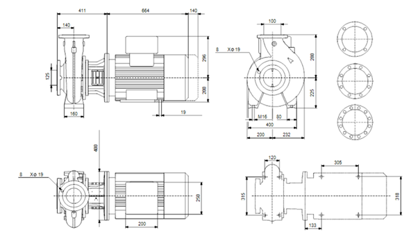
Figure 1. Dimensional Drawing of End Suction Close-coupled single-stage: NBG 125-100-250/275 VBAF2CESBQQESY1
End Suction Long Coupled Single Stage
Model: NK 350-350/416-382 AA1F1SBESBQQEYW3
Head: 34.45 m
Pump Speed: 1485 RPM
Rated Flow: 1917 m³/h
Actual Impeller Diameter: 399 mm
Nominal Impeller Diameter: 350 mm
Liquid temperature range: -25 – 120 °C
Pressure: 10 bar
Mains Frequency: 50 Hz
IE Efficiency: IE3 96%
Motor Type: 315L
Rated power – P2: 200 kW
Motor Efficiency at Full Load: 96% – 96%
Max. Particle: 25 mm
Shaft diameter: 60 mm
Mechanical Seal Type: Single
Code for shaft seal: BQQE
Curve tolerance: ISO9906:2012 2B
Pump Version: A1
Bearing design: Standard
Net Weight: 2270 kg
Gross Weight: 2430 kg
Shipping Volume: 5.6 m³
Materials
Pump Housing: DUCTILE IRON
EN 1563 EN-GJS-500-7
ASTM 70-50-05
Impeller: Stainless steel
EN 1.4308
ASTM A351 CF8
Internal Pump House Coating: Painting
Material Code: SB
Code for Rubber: E
Shaft: Steel
EN 1.0503/1.4301
AISI 1045/304
Applications:
- Water Treatment Fertigation, Chemigation & Dosing
- Irrigation
- Desalination
- Community water supply
- Water distribution
- Wastewater treatment
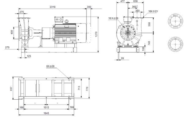
Figure 2. Dimensional Drawing of End Suction Long coupled single-stage: NK 350-350/416-382 AA1F1SBESBQQEYW3
Xylem
Xylem is a multinational manufacturer of sensors, pumps, monitoring, and control equipment intended especially for use in industrial and municipal wastewater treatment applications. Products from Xylem’s international brands have been sold in more than 150 countries, catering to the water market for many years. Xylem provides cutting-edge water technology solutions for the entire water cycle in a world where challenges are only getting bigger.
Xylem can be considered the second-best option to purchase End Suction Pump. The company is well known for its innovative technologies and reduced life cycle cost of products.
Xylem’s manifesto is;
“Xylem serves a variety of industries, such as public utilities, agriculture, building, construction, environmental, food and beverage, government agencies, and industrial and commercial building services. With extensive application knowledge in the water sector, we concentrate on developing extremely energy-efficient water solutions that lower lifecycle costs, benefit users and the communities where they operate, and improve the environment.”
Goulds Water Technology e-NSC – Series
Rated Flow: up to 1800 m³/h
Head: up to 160 m
Power Supply: three-phase 50 and 60 Hz
Power: 0.25 – 355 kw
Maximum Operating Pressure: 16 bar
Temperature Of Pumped Liquid: -25°C – +140°C
Motor Efficiency: IE3 or higher-rated motors
F (155°C) insulation class
Protection grade: IP55 – 50Hz and 60Hz voltages
A wide range of motor options
Material: Stainless Steel
Cast Iron
Applications:
- Municipal Water and Wastewater
- Water transfer and distribution
- Water intake and monitoring solutions for clean water
- Municipal Sewage Handling & Waste Treatment
- HVAC Heating
- HVAC Cooling
- Mine Water Boosting & Transport – Pumps, Monitoring and Controls
- Offshore Oil Platform Water Management
Figure 3. Goulds Water Technology e-NSC – Series
Bell & Gossett Series e-1535 Close-Coupled Small End Suction Pumps
Model: e3509T
Pump Size: 1.25AAC
Pump Construction: Cast Iron-BF (Brz Fitted)
Pump Class: Centrifugal
Pump Mounting: Foot-Mounted
Pump Connection Size: 1-1/2″ x 1-1/4″
Pump Connection: Threaded
Flanges Included: N/A
Motor HP: 1/2 HP
Motor RPM: 1725 RPM
Motor Voltage: 208-230/460V
Motor Phase: 3 Ph
Motor Hertz: 60 Hz
Shaft Size: 5/8″
Impeller Size: 5″
Working Pressure: 175 psi
Max Temp: 250℉
Weight: 55.00 kg
Material:
Volute: Cast Iron ASTM #A159
Impeller: ASTM #B584
Volute Gasket: Cellu-Fiber
Shaft: Stainless Steel
Bracket: Cast Iron – ASTM #A48
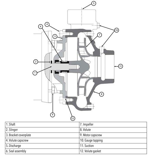
Figure 4. Cross-Sectional View of Bell & Gossett Series e-1535 Close-Coupled Small End Suction Pumps
Frequently Asked Questions
What is an end suction pump?
An end suction pump is a single-stage centrifugal pump in which liquid enters axially through a suction connection at the end of the casing and leaves radially through a discharge connection at the top. The impeller is overhung on the shaft, supported by bearings on one side only, which is what makes the design compact and inexpensive. It is the most widely installed pump configuration in water, wastewater, HVAC, and general industrial service.
What is the difference between end suction and split case?
An end suction pump takes flow into one side of a single-suction impeller with the impeller overhung on the shaft. A split case pump uses a double-suction impeller supported between two bearings, with the casing split along the shaft centerline. The double-suction arrangement halves inlet velocity, which lowers the NPSH requirement, and it balances axial thrust hydraulically. End suction is more economical up to roughly 1,500 to 2,000 gpm; above that, or where suction conditions are marginal, split case is generally the better choice.
Why does an end suction pump need priming?
A standard centrifugal impeller cannot generate enough differential pressure to move air, so an air-filled casing produces no flow at all. The pump must be filled with liquid before starting, either by a flooded suction arrangement, a foot valve and manual fill, or a vacuum priming system. Self-priming variants add an integral priming chamber that retains liquid between runs, allowing them to evacuate the suction line on their own within their rated lift.
How do I know if my pump is running at its best efficiency point?
Measure discharge pressure and suction pressure to calculate total dynamic head, then find that head on the manufacturer’s curve for your installed impeller diameter and read across to flow. Compare that flow with the BEP flow marked on the curve. Motor amperage provides a useful cross-check, since it should correspond to the power curve at the same point. A pump running well right of BEP will show high amps and low discharge pressure; one running left of BEP will show high pressure and lower flow than expected.
What causes cavitation in an end suction pump?
Cavitation occurs when pressure at the impeller eye falls below the vapor pressure of the liquid, forming bubbles that collapse violently as pressure recovers. The usual causes are insufficient NPSH available from excessive suction lift or a restricted suction line, operation far to the right on the curve where required NPSH climbs, elevated liquid temperature, and air entrainment. The remedy is almost always on the suction side: raise the liquid level, shorten or enlarge the suction piping, reduce the flow, or lower the pump.
How long should an end suction pump last?
The casing and bearing frame commonly remain serviceable for 20 years or more in clean-water duty, with mechanical seals replaced every few years and wear rings restored during periodic rebuilds. Abrasive and chemical service shortens every interval considerably. Service life depends far more on how close the pump runs to BEP, on the quality of the seal flush, and on the match between materials and water chemistry than on the brand purchased.
Can end suction pumps handle solids?
Standard enclosed-impeller units cannot; their tight internal clearances foul or erode quickly on solids-bearing fluid. Non-clog variants with two-vane, single-vane, or vortex impellers are built for wastewater duty and carry a defined solids passage rating, at the cost of some efficiency. The distinction matters, because a general-service end suction pump installed on raw wastewater will clog repeatedly regardless of how well its hydraulic duty point was matched.
Conclusion
Key Takeaways
- End suction is the economical default, within limits — the overhung single-suction design is the cheapest and most compact configuration up to roughly 1,500 to 2,000 gpm, above which split case or vertical turbine construction usually wins.
- Run near BEP or pay for it — operating far left or right of best efficiency point produces recirculation, shaft deflection, and seal failure, and the acceptable band is roughly 70 to 120 percent of BEP flow.
- Oversizing is the most common and most expensive mistake — a safety margin added to calculated head pushes the pump left of BEP permanently.
- NPSH margin must hold at worst case, not at the duty point — required NPSH climbs steeply toward runout, and end suction designs are more suction-sensitive than double-suction ones.
- Materials follow water chemistry, not service labels — chloride concentration and temperature decide between cast iron, 316 stainless, and duplex, as covered under the materials comparison above.
- B73.1 dimensional standardization shifts brand selection to service — because units are interchangeable on a common baseplate, spares availability and local support matter more than hydraulic differences between the Top End Suction Pump Manufacturers.
End suction pumps earn their position as the most widely installed configuration in water and wastewater service through simplicity: the fewest parts, the smallest footprint, the lowest first cost, and dimensional standards that keep the installed base interchangeable across suppliers. The trade-offs are equally clear, in suction sensitivity, a practical capacity ceiling, and limited tolerance for solids unless a non-clog variant is specified.
Selecting one well comes down to a short sequence: build an honest system curve, place the operating point near best efficiency, verify NPSH margin at worst case rather than at the duty point, match wetted materials to actual water chemistry, and plan the seal arrangement around the fluid the pump will really see. Where those decisions are made deliberately, and where the operating point is checked periodically rather than assumed, an end suction pump is among the most reliable and least expensive pieces of rotating equipment a treatment plant will own.