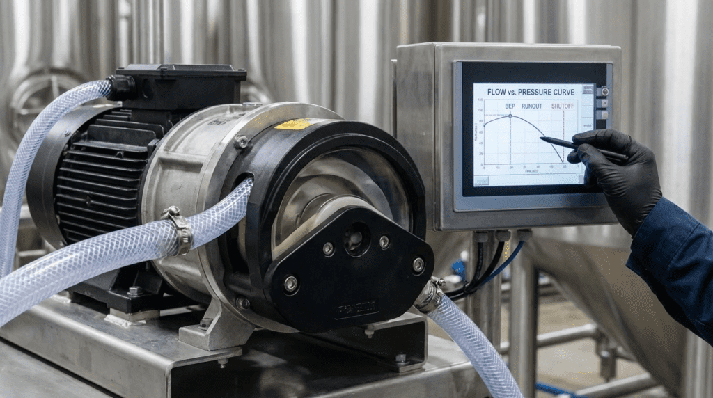
Peristaltic Pump Curve Reading for Operators (BEP Runout Shutoff and Control)
Introduction
One of the most dangerous misconceptions in hydraulic engineering is the attempt to apply centrifugal pump logic to positive displacement equipment. Engineers trained to identify the Best Efficiency Point (BEP), check for runout, and evaluate shutoff head on a standard curve often find themselves disoriented when presented with a peristaltic (hose) pump performance chart. This confusion is not merely academic; misinterpreting Peristaltic Pump Curve Reading for Operators (BEP Runout Shutoff and Control) can lead to catastrophic over-pressurization events, rapid hose failure, and inefficient process control.
Unlike centrifugal pumps, where pressure creates flow, peristaltic pumps create flow essentially independent of pressure—until the hose bursts or the motor stalls. In municipal water treatment (chemical dosing, lime slurry) and wastewater applications (thickened sludge, scum, digester feed), the peristaltic pump is often the technology of choice for its ability to handle high solids, high viscosity, and shear-sensitive fluids. However, the “curve” is fundamentally different. It is a linear relationship between speed and flow, bounded by the mechanical limitations of the hose material rather than hydraulic inefficiency.
The consequences of poor specification based on incorrect curve reading are severe. A centrifugal pump dead-headed against a closed valve may churn and overheat; a peristaltic pump in the same scenario will build pressure with every revolution until the piping ruptures or the pump housing fractures. Conversely, undersizing a peristaltic pump by running it too fast—trying to hit a “Runout” point that doesn’t exist—decimates hose life from months to days.
This article provides a rigorous technical framework for engineers and operators to correctly interpret performance data, specify control strategies, and manage the lifecycle of peristaltic pumping systems, moving beyond the myths of centrifugal hydraulics.
How to Select / Specify
Selecting a peristaltic pump requires a mindset shift from hydraulic efficiency to mechanical endurance. The selection process revolves around the hose—the only wetted part and the primary wear component. When analyzing Peristaltic Pump Curve Reading for Operators (BEP Runout Shutoff and Control), the goal is not to find a hydraulic sweet spot, but to match the pump’s displacement per revolution to a rotational speed that yields acceptable hose life.
Duty Conditions & Operating Envelope
The operating envelope of a peristaltic pump is defined by torque (pressure) and heat (speed). Engineers must specify:
- Flow Rate (Continuous vs. Peak): Since flow is linear with speed, pumps should be sized so that continuous duty occurs at 30-40% of the maximum rated speed. Running a peristaltic pump at 100% of its catalog speed continuously will result in unacceptably short hose life.
- Discharge Pressure: This dictates the “shoe” or “roller” force required to occlude the hose. Higher pressures require tighter occlusion, which increases compressive stress on the hose and shortens life.
- Suction Conditions: While peristaltic pumps have excellent suction lift (up to 29-30 ft or 9m water column), high viscosity fluids significantly reduce this capability. The “curve” must be de-rated for Net Positive Suction Head Available (NPSHa) when handling sludge >2% solids.
Materials & Compatibility
The hose specification is the single most critical decision. Unlike centrifugal pumps where impeller metallurgy varies, here the elastomer is the limiting factor.
- Natural Rubber (NR): Excellent abrasion resistance, ideal for grit, sand, and lime slurry. Poor resistance to oils and petroleum products.
- EPDM: Excellent chemical resistance for acids and caustics used in disinfection and pH adjustment. Not suitable for oil-based polymers.
- Nitrile (NBR): Required for oily waste, polymers, or sludge with hydrocarbon content.
- Hose Restitution: This is the “spring back” property of the hose. At high speeds, a hose may not have time to return to its round shape before the next roller compression. This phenomenon, effectively the “Runout” limit of a peristaltic pump, causes a drop in volumetric efficiency.
Hydraulics & Process Performance
There is no “BEP” on a peristaltic curve. Efficiency is relatively flat across the speed range, though volumetric efficiency drops slightly at higher pressures due to backflow (slip) through the occlusion point.
Process constraints often dictate the pump type. For example, in Return Activated Sludge (RAS) or flocculant dosing, low shear is mandatory. Peristaltic pumps impart very low shear compared to centrifugal options, preserving floc structures. Engineers must verify that the selected pump speed (RPM) is low enough to maintain this low-shear characteristic.
Installation Environment & Constructability
Peristaltic pumps are generally self-priming and can run dry indefinitely, offering flexibility in placement. However, they are distinctively pulsing machines.
- Pulsation: The flow output is sinusoidal. Every time a roller leaves the hose, there is a momentary drop in flow and pressure. Large peristaltic pumps can shake poorly supported piping systems apart.
- Space: While the pump head is compact, the maintenance envelope is large. Operators need significant clearance (often equal to the hose length) to extract and replace the hose element from the side or front of the housing.
Reliability, Redundancy & Failure Modes
The Mean Time Between Failure (MTBF) of a peristaltic pump is synonymous with hose life. Hose failure is not a question of “if,” but “when.”
- Hose Life Prediction: Manufacturers provide curves estimating hose life based on speed and pressure. A pump running at 20 RPM might last 4,000 hours, while the same pump at 60 RPM might last only 1,500 hours.
- Leak Detection: Redundancy requires automated leak detection sensors (conductivity or float type) in the pump housing. Upon hose rupture, the housing fills with process fluid; the sensor must trigger an immediate pump shutdown to prevent chemical spills or gearbox contamination.
Controls & Automation Interfaces
Control logic is simplified by the linear nature of the pump. A 4-20mA signal usually maps directly to 0-100% speed.
- Flow Pacing: In dosing applications, the pump speed often follows a main line flow meter signal. The response is immediate and proportional.
- Start/Stop Logic: Soft starts are recommended to reduce torque spikes on the gearbox, although peristaltic pumps have high starting torque requirements due to the constant compression of the hose.
Maintainability, Safety & Access
Safety is paramount regarding “Shutoff” conditions. Because the pump is a positive displacement device, it will continue to build pressure if a discharge valve is closed.
Lifecycle Cost Drivers
The lifecycle cost profile of a peristaltic pump is OPEX-heavy. CAPEX is moderate, but the cumulative cost of replacement hoses and lubricant (glycerin or silicone) over 20 years can exceed the initial pump cost significantly. Energy efficiency is generally lower than centrifugal pumps due to the friction of the shoes/rollers against the hose, but this is often offset by the elimination of seal water systems and check valve maintenance.
Comparison Tables
The following tables assist engineers in positioning peristaltic technology against other positive displacement options and determining the best application fit based on fluid characteristics. These comparisons assume standard municipal and industrial wastewater constraints.
Table 1: Technology Comparison – PD Pumps in Wastewater
| Feature | Peristaltic (Hose) Pump | Progressive Cavity (PC) Pump | Diaphragm (Metering) Pump | Rotary Lobe Pump |
|---|---|---|---|---|
| Flow Characteristics | Pulsing flow; Linear with speed | Non-pulsing, smooth flow; Linear | High frequency pulse; Linear | Low pulse; Linear (slip dependent) |
| Dry Run Capability | Excellent (Indefinite) | Poor (Stator burns immediately) | Good (Hydraulic diaphragm types) | Poor (Requires seal flush/cooling) |
| Solids Handling | Excellent (Full bore, no valves) | Good (Depends on universal joints) | Poor (Check valves clog) | Good (Compressible solids) |
| Shear Sensitivity | Very Low (Gentle handling) | Low | Medium/High (Valve turbulence) | Medium (Gap shear) |
| Maintenance Focus | Hose replacement (Frequent but predictable) | Rotor/Stator (Expensive, difficult labor) | Check valves & Diaphragms | Lobes & Mechanical Seals |
| Best Application | Abrasive slurries, High suction lift, Dosing | Thick sludge, Cake pumping | Clean chemical metering | High volume sludge, Scum |
Table 2: Application Fit Matrix
| Application Scenario | Typical Fluid | Key Constraint | Curve Reading Focus | Relative Cost (TCO) |
|---|---|---|---|---|
| Chemical Dosing | Sodium Hypochlorite, Alum, Ferric | Gas locking (Hypo), Accuracy | Low speed for accuracy; Turndown ratio | Medium (Hose chemical attack) |
| Thickened Sludge Transfer | 4-8% Solids TWAS | High Viscosity, Friction Loss | Derate capacity for viscosity (suction fill) | High (Energy intensity) |
| Lime Slurry Feed | Lime Slurry (Abrasive) | Abrasion, Sedimentation | Velocity must prevent settling; Hose life | Low (Cheaper than repairing PC rotors) |
| Digester Feed | Primary/Secondary Sludge | Variable Solids, Ragging | Passage size (Inner Diameter) | Medium |
| Filter Press Feed | Conditioned Sludge | High Pressure (100+ PSI) | Max pressure rating; High hose stress | High (Short hose life at high pressure) |
Engineer & Operator Field Notes
Practical experience often diverges from the catalog data. This section covers the nuance of Peristaltic Pump Curve Reading for Operators (BEP Runout Shutoff and Control) in the field, specifically regarding commissioning and troubleshooting.
Commissioning & Acceptance Testing
When commissioning a peristaltic pump, the “curve” verification is actually a volumetric calibration.
- Calibration Columns: Every chemical metering peristaltic pump requires a suction-side calibration column. The operator isolates the supply tank, draws from the column for a set time (e.g., 30 seconds), and calculates the actual drawdown volume. This establishes the “Volume Per Revolution” for that specific installation.
- Shim Adjustment: For pumps with adjustable shoes, the “squeeze” or occlusion must be set. Over-shimming increases pressure capability but drastically reduces hose life and increases energy draw. Under-shimming causes backflow (slip), where fluid shoots back through the gap, eroding the hose liner rapidly. The correct setting is the minimum compression required to prevent slip at the target discharge pressure.
- Pulsation Dampener Charge: Dampeners must be charged with nitrogen to approximately 80-85% of the system operating pressure. If the system pressure changes, the charge must be adjusted.
Common Specification Mistakes
Sludge with high viscosity does not fill the hose as quickly as water. As the hose expands after compression (restitution), it creates a vacuum. If the fluid is too thick to fill that void before the next roller arrives, the pump suffers from “starvation” or cavitation. This reduces flow well below the theoretical curve. Engineers must apply a Viscosity Correction Factor, often requiring the pump to be oversized and run slower to allow time for the hose to fill.
O&M Burden & Strategy
Maintenance strategy for peristaltic pumps is predictive. Operators should not wait for a hose to burst.
- Cycle Counting: Modern VFDs or PLC logic should track the total number of pump revolutions. If a hose is rated for 2 million cycles, maintenance should be scheduled at 1.8 million cycles.
- Lubricant Levels: The pump housing is typically filled with a lubricant that cools the hose and reduces friction. Low levels lead to heat buildup—the enemy of rubber. Operators must check levels monthly.
- Roller/Shoe Inspection: While the hose is the sacrificial part, rollers and bearings eventually wear. A seized roller will drag across the hose, causing immediate failure.
Troubleshooting Guide
Symptom: Low Flow / Instability
Root Cause: Suction line restriction or high viscosity preventing hose refill (incomplete restitution).
Fix: Increase suction line diameter, reduce pump speed, or install a vacuum assist device.
Symptom: Loud Knocking
Root Cause: Water hammer or un-dampened pulsation.
Fix: Check pulsation dampener charge; verify discharge piping support.
Symptom: Short Hose Life
Root Cause: Pump running too fast (heat), over-shimming (mechanical stress), or chemical incompatibility.
Fix: Verify chemical resistance chart; reduce speed (may require larger pump); check shim settings.
Design Details / Calculations
To properly interpret Peristaltic Pump Curve Reading for Operators (BEP Runout Shutoff and Control), engineers must understand the underlying math of positive displacement sizing.
Sizing Logic & Methodology
The fundamental equation for peristaltic pump flow is:
Q = Vdisp × RPM × ηvol
Where:
- Q: Flow Rate (e.g., Gallons Per Minute)
- Vdisp: Volume displaced per revolution (Gallons/Rev)
- RPM: Pump Speed
- ηvol: Volumetric Efficiency (typically 0.95 – 1.00 for properly occluded pumps)
Step 1: Determine Peak Flow and Pressure. Identify the worst-case scenario (e.g., peak wet weather flow for sludge pumps).
Step 2: Select Pump Model based on “Continuous Duty” Speed. Do not select a pump where the peak flow requires the maximum rated RPM. Select a model that can deliver the peak flow at roughly 50-70% of its max RPM, and average flow at 30-40% RPM.
Step 3: Verify Torque. Ensure the gearbox and motor can supply the starting torque, which is high due to the static compression of the hose.
Step 4: Check Suction Capability. Calculate the NPSHa. If the fluid is viscous, calculate the friction loss in the suction line carefully. Peristaltic pumps can pull a vacuum, but if the friction loss exceeds 14.7 psi (vacuum), the liquid will boil or vaporize (cavitation).
Specification Checklist
When writing the equipment specification, include the following mandatory items to ensure safety and performance:
- Leak Detection: “Pump shall be equipped with a capacitive or float-style leak detector capable of shutting down the motor upon detection of fluid in the housing.”
- Roller vs. Shoe: Specify “Roller” technology for lower friction and energy consumption, or “Shoe” technology for higher pressure capabilities (typically >120 psi).
- Pulsation Dampeners: “Discharge piping shall include a pulsation dampener sized to limit pressure fluctuation to +/- 5%.”
- Maintenance Access: “Pump housing shall allow for hose removal without uncoupling the drive motor or removing the pump from the baseplate.”
Standards & Compliance
While there is no specific AWWA standard solely for peristaltic pumps (unlike ANSI/HI for centrifugal), the following apply:
- Hydraulic Institute (HI) 9.6.1 – 9.6.7: Guidelines for NPSH and vibration.
- API 676: While written for rotary positive displacement pumps in oil/gas, many principles regarding testing and documentation are relevant for high-spec industrial wastewater projects.
- NSF 61: Mandatory for the hose material if the pump is dosing chemicals into potable water.
Frequently Asked Questions
What is the “Shutoff Head” of a peristaltic pump?
Technically, a peristaltic pump has no hydraulic shutoff head. If the discharge is blocked, the pump will continue to build pressure until the torque limit of the motor is reached, the hose bursts, or the piping fails. This is a critical safety distinction from centrifugal pumps. You must never rely on the pump to “dead head.” A pressure relief valve or rupture disc is mandatory in the discharge line.
Why is there no Best Efficiency Point (BEP) on a peristaltic curve?
BEP is a concept related to centrifugal hydraulics where incidence angles and flow vectors minimize losses. Peristaltic pumps are positive displacement machines; their mechanical efficiency is dominated by friction (hose compression) and gearbox losses. While they don’t have a hydraulic BEP, they do have a “Best Reliability Point,” which is generally at low speeds (20-30% of max RPM) where heat generation and hose fatigue are minimized.
How does “Runout” apply to peristaltic pumps?
It doesn’t apply in the centrifugal sense (where flow increases as head drops). For peristaltic pumps, the equivalent limit is the Restitution Limit. If you run the pump faster than the hose can naturally spring back to its round shape, the hose remains partially flattened when the next roller arrives. This causes a dramatic drop in flow per revolution (efficiency loss) and rapid overheating. This is the mechanical speed limit of the pump.
How do I control flow with a peristaltic pump?
Flow control is linear and simple. Because the pump displaces a fixed volume per revolution, you control flow by changing the motor speed via a Variable Frequency Drive (VFD). A 4-20mA signal from SCADA typically scales 1:1 with speed. For example, 12mA (50% signal) results in 50% speed and roughly 50% flow. This linearity makes them excellent for pacing loops.
How often should peristaltic hoses be replaced?
Hose life depends entirely on speed, pressure, and temperature. A pump running 24/7 at high pressure might need a hose change every 3 months (approx. 2,000 hours). A pump running intermittently at low pressure could last 12-18 months. Best practice is to log the number of revolutions and replace the hose proactively before failure, typically based on the manufacturer’s life-curve data.
Can peristaltic pumps run dry?
Yes, this is a primary advantage. They can run dry indefinitely without damage because the pumped fluid does not provide cooling or lubrication for the bearings or seals (the hose is lubricated externally by the bath in the housing). This makes them ideal for tank unloading or intermittent flows where suction might be lost.
How does viscosity affect peristaltic pump sizing?
High viscosity fluids resist flow into the pump suction. As viscosity increases, the maximum allowable pump speed decreases. If you run a pump too fast with thick sludge, the hose won’t fill completely (low volumetric efficiency). Engineers must use viscosity correction charts to de-rate the maximum speed, often resulting in selecting a larger pump body to achieve the required flow at a lower RPM.
Conclusion
KEY TAKEAWAYS
- Forget BEP: Focus on “Best Reliability Speed.” Size pumps to run slowly (30-50% max RPM) for continuous duty to maximize hose life.
- Danger of Shutoff: Unlike centrifugal pumps, PD pumps generate infinite theoretical pressure. Pressure relief valves are mandatory.
- Linear Control: Flow is directly proportional to speed. “Curves” are straight lines. Control logic is simpler than centrifugal systems.
- Viscosity Matters: Thick fluids reduce the effective speed limit of the hose (restitution issues). De-rate capacity for sludge.
- OPEX Reality: The hose is a consumable. Budget for regular replacement and lubricant costs in the lifecycle analysis.
- Pulsation: Install dampeners on both suction and discharge if lines are long or rigid to prevent pipe fatigue.
Mastering Peristaltic Pump Curve Reading for Operators (BEP Runout Shutoff and Control) requires unlearning the habits of centrifugal pump selection. The “curve” is not a hydraulic map of efficiency islands and head limitations, but a mechanical guide to hose endurance. The operator’s goal is not to find a hydraulic balance point, but to manage the number of occlusions (compressions) the hose endures over time.
For municipal and industrial engineers, the peristaltic pump offers unmatched performance for abrasive, viscous, and chemically aggressive fluids, provided the design respects the mechanical limits of the elastomer. By specifying low operating speeds, ensuring appropriate pulsation dampening, and installing critical safety relief systems, engineers can deploy these pumps to solve the most difficult transfer and dosing challenges in the water sector. The success of the installation relies less on reading a complex curve, and more on understanding the simple, brutal physics of compressing a rubber hose millions of times.