
Remote Control Range’s Compact Pneumatic Actuators
A Powerful and Versatile Pneumatic Actuator
Pneumatic Actuators in Water and Wastewater Service
Automation decisions in a treatment plant almost always come down to the actuator, not the valve body. A correctly specified quarter-turn valve with an undersized or poorly configured actuator will stall on the first slug of grit, drift out of position on a failing air supply, or slam closed fast enough to send a pressure transient back through the header. Actuators are the part of the valves used in water treatment plants that convert a control signal into mechanical work, and they carry most of the reliability risk in an automated process loop.
Pneumatic actuators remain the dominant choice wherever a plant already has an instrument air system. They are inherently spark-free, tolerate wash-down and high-humidity environments, deliver fast stroke times, and provide true fail-safe action through a spring return without any dependence on backup power. Typical municipal installations run them on instrument air at approximately 60 to 100 psig, with 80 psig being the most common design point for torque calculations. Above roughly 24-inch valve sizes, or where instrument air is unavailable, electric actuation usually takes over on lifecycle cost grounds.
The pneumatic actuator category spans several distinct construction types. Rack-and-pinion units are the workhorse for quarter-turn service up to moderate torque, using two opposed pistons driving a central pinion for linear torque output across the full 90-degree travel. Scotch-yoke actuators produce high breakaway torque at the start and end of travel, which matches the torque curve of a seated butterfly or ball valve and makes them the standard for larger or higher-pressure applications. Linear cylinder actuators, including the compact designs reviewed in this article, drive gate valves, knife gates, sluice gates, and dampers directly. Diaphragm actuators handle modulating control valve service where fine positioning matters more than raw thrust.
This hub covers the actuator category from four angles: the manufacturer landscape and how the major brands differentiate, actuation for abrasive and high-solids duty, the automation and control layer that sits between the DCS or SCADA system and the cylinder, and the material and safety constraints that apply when actuators operate chemical feed valves. Each of those areas has its own selection logic, its own failure modes, and its own specification pitfalls.
The sections below start with a detailed product review of one compact linear actuator family, then widen out into the subcategory overview, selection framework, comparison data, field notes, and standards that apply across the whole actuator category.
Remote Control Range Compact Pneumatic Actuators: Product Review
Rotork acquired Remote Control Sweden, a manufacturer of pneumatic linear actuators, to expand its actuation product portfolio. Remote Control Sweden is known for its compact, lightweight cylinder designs in automation across industries. According to Rotork, this strategic acquisition strengthens its position in pneumatics by adding Remote Control Sweden’s advanced technologies to its electric and hydraulic actuator offerings. The deal provides Rotork with additional technical expertise and distribution reach. Overall, it represents a synergistic opportunity for both companies to leverage combined strengths in the actuation market.
Remote Control Range’s Compact Pneumatic Actuators are a fantastic solution for linear motion and force applications. As an engineer, I frequently use pneumatic actuators and was impressed by the power packed into these small, lightweight actuators.
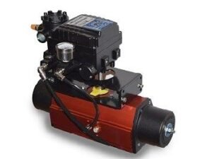 The key features that make these actuators stand out are:
- Compact size – Despite their small footprint, these actuators deliver powerful pushing/pulling force up to 1000 lbs. This makes them perfect for confined spaces.
- Dual-action – Unlike single-acting cylinders, they provide both outward and inward linear motion. This bidirectional control is ideal for clamps, presses, and grippers.
- Remote air control – Built-in 5-port valves allow you to remotely control the actuators by adjusting air pressure. This is much more convenient than manually attaching airlines.
- Interchangeable mounts – The actuators come with clevis, trunnion, and threaded mounts for easy installation. You can switch mounts to suit different applications.
- Durable construction – Hard coat anodized aluminum body and stainless steel rods withstand harsh conditions and last long.
Remote Control Range’s pneumatic actuators are versatile and enable remote linear motion control in compact spaces. Their convenient features and rugged build quality make them great for industrial, manufacturing, and automation applications. I highly recommend these powerful little actuators.
Comparison of Remote Control Range’s Compact Pneumatic Actuators to another popular model:
Remote Control Range vs. Airpel E9 Series Actuators
Size and Weight: The Remote Control Range actuators are more compact and lightweight than the Airpel E9 series. The most minor Remote Control Range model measures 1.25 x 1.25 x 5 inches and weighs 0.55 lbs. In contrast, the Airpel E9 starts at 1.77 x 1.77 x 5.51 inches and weighs over 1 lb. This makes the Remote Control Range better suited for tight spaces.
Force Output: Despite their smaller size, the Remote Control Range actuators match or exceed the force capabilities of the Airpel E9 series. The maximum force ranges from 250 to 1000 lbs, depending on the Remote Control Range model. The Airpel E9 in a similar size provides up to 660 lbs of force.
Control Options: The built-in 5-port valve on the Remote Control Range allows remote push-button control of the actuator using air pressure. The Airpel E9 does not have built-in control valves, so it requires manually attaching airlines to control.
Stroke Length: The Remote Control Range actuators offer stroke lengths up to 6 inches. The Airpel E9 has a slightly longer maximum stroke length of 8 inches. However, the Remote Control Range strokes are sufficient for most applications requiring short linear motions.
Price: The Remote Control Range actuators are around 25-50% lower in price than comparable Airpel E9 models. This cost savings makes them very appealing, especially for budget-conscious projects.
In summary, the Remote Control Range pneumatic actuators win out for compact size, convenient remote control, and lower cost. They offer comparable power and stroke length to the popular Airpel E9 models. The Remote Control Range actuators provide better value and flexibility for most applications requiring short linear motions. Their remote air control and small footprint are key advantages that make them my top pick.
Common Mistake: Reading a Catalog Force Rating Without Its Supply Pressure
Published thrust and torque figures are meaningless without the supply pressure they were measured at. Pneumatic output follows the relationship F = P x A, where F is thrust in pounds-force, P is gauge supply pressure in psi, and A is the effective piston area in square inches. A cylinder with a 1.25-inch bore has an effective area of roughly 1.2 square inches and produces approximately 96 lbf at 80 psig, not several hundred. Figures at the top of a product family’s stated range almost always belong to the largest bore in that family, often at maximum rated pressure. Always confirm which bore, which pressure, and whether the number is push (full piston area) or pull (piston area minus rod area, typically 10 to 25 percent lower). Specify against the actual bore you intend to buy, at your plant’s minimum guaranteed header pressure, not the nameplate maximum.
Actuator Subcategory Overview
The actuator category divides into four working areas. Each addresses a different part of the specification problem, and most projects touch at least two of them.
Manufacturer Landscape and Brand Selection
The Top Valve Actuator Manufacturers area covers how the major actuation brands differentiate on torque range, control electronics, spare parts availability, and service network depth. Rotork, Auma, Emerson (Bettis), Flowserve (Limitorque), Valmet (Neles), Festo, SMC, Kinetrol, and Air Torque cover the bulk of municipal and industrial installations, and each has a distinct sweet spot. Rotork and Auma dominate the large-torque end and carry the most mature diagnostic and asset-management platforms, which matters if the plant intends to trend torque signatures over time. Festo, SMC, and Air Torque compete on compact rack-and-pinion units at lower cost with faster commercial lead times, which suits repeat small-valve work such as chemical feed skids and filter gallery automation. The practical selection criteria that separate these brands are rarely torque alone: mounting-kit availability for your specific valve, local service technician coverage, spare seal-kit stocking, and whether the manufacturer’s positioner speaks the plant’s existing protocol. Standardizing on one or two brands across a facility reduces spares inventory and shortens operator training substantially, and that consideration usually outweighs a modest per-unit price difference.
Abrasive and High-Solids Duty
Specifying actuators for slurry service is a torque and travel-time problem before it is anything else. Grit, rag, struvite, and dewatered biosolids build up on seats and in the valve bore, so breakaway torque climbs steadily over the service interval rather than staying at the manufacturer’s clean-water figure. Where clean water service tolerates a 1.25 to 1.5 torque safety factor, abrasive duty commonly warrants 1.75 to 2.0, and knife gate valves in thickened sludge sometimes need more. Cycling frequency also matters: valves that sit in one position for weeks accumulate the heaviest deposits and are the ones most likely to stall, which argues for a scheduled exercise routine rather than a larger actuator alone. Linear cylinder actuators driving knife gates in this service should be sized with enough stroke margin to shear accumulated solids at the seat, and the exhaust should be throttled to avoid slamming a gate through a solids bed. Position feedback is worth the cost here, because a stalled actuator that never reaches its seat looks identical to a healthy one on a simple open or closed limit switch.
Automation, Control, and Signal Integration
The actuator automation area covers everything between the control system output and the piston: solenoid pilots, positioners, I/P transducers, limit switches, volume boosters, quick-exhaust valves, and speed controls. A basic on/off installation uses a three-way pilot for spring-return service or a four-way pilot for double-acting service, mounted to a NAMUR interface, with a dual limit-switch box reporting position back to SCADA. Modulating service replaces the pilot with a positioner that accepts a 4-20 mA signal, or a digital valve controller that adds HART diagnostics, travel deviation alarms, and stroke counting. Stroke speed is set with needle valves on the exhaust ports rather than the supply, since throttling supply air starves the actuator of the force it needs to break away. Fail position is a design decision made at this layer as much as at the actuator: a spring return defines the mechanical default, while an air-reservoir and check-valve arrangement can instead drive a double-acting unit to a defined position on air loss.
Chemical Feed and Material Compatibility
Selecting actuators for chemical systems shifts the emphasis from torque to materials, fail-safe logic, and code compliance. Sodium hypochlorite, ferric chloride, sodium hydroxide, sulfuric acid, and polymer all attack standard actuator hardware in different ways: hypochlorite off-gassing corrodes aluminum housings and carbon steel fasteners, ferric stains and seizes exposed linkages, and caustic degrades some elastomers. Practical answers include hard-anodized or epoxy-coated aluminum bodies, 316 stainless fasteners, stainless or polymer mounting brackets, and enclosure ratings of at least NEMA 4X for wash-down and chemical-room atmospheres. Fail position deserves specific attention: most chemical feed valves should fail closed so that a loss of air or control power stops chemical addition rather than continuing it unattended. Gas chlorine systems are a distinct case, where fire-code-driven emergency shutoff requirements dictate both the actuator’s fail action and its response time. Spring-return construction is strongly preferred throughout chemical service because it does not depend on stored air volume to reach the safe position.
Selection and Specification Framework
Step One: Establish the Required Torque or Thrust
Start from the valve manufacturer’s published torque values at the actual differential pressure, not the valve’s pressure class. For quarter-turn valves, four numbers matter: break-to-open, run-to-open, end-to-open, and break-to-close. The controlling value is usually break-to-close or break-to-open, since seated torque exceeds running torque by a wide margin, particularly on resilient-seated designs. Apply the safety factor appropriate to the service, then confirm that the actuator meets or exceeds the requirement at the plant’s minimum guaranteed air pressure. Sizing at 80 psig and then operating a header that sags to 55 psig on a compressor changeover is one of the most common causes of intermittent stalling.
Step Two: Choose Fail Action
Fail-closed, fail-open, and fail-in-place each answer a different process question. Chemical feed, plant water makeup, and anything that could overflow a structure generally fails closed. Cooling water, seal water, and pressure relief paths generally fail open. Fail-in-place suits large modulating valves where either extreme creates a hydraulic problem, but it requires either a double-acting actuator with a lock-up valve and air reservoir or a switch to electric actuation. Spring-return actuators are typically one or two frame sizes larger than double-acting units for the same torque, because the spring absorbs a meaningful share of air-stroke output and the air stroke must compress it.
Step Three: Match the Actuator Type to the Duty Cycle
Modulating service that strokes hundreds of times per day needs a diaphragm or scotch-yoke actuator with a positioner and a bearing arrangement rated for continuous travel. On/off isolation service cycling a few times per week is well served by a rack-and-pinion unit. Linear cylinders suit gates, knife gates, sluice gates, and dampers, where the load is a straight-line push and pull. Quarter-turn valve bodies such as butterfly valves are the most commonly actuated valve type in water and wastewater plants, and their dynamic torque behavior near the 60 to 70 degree open position is a frequent source of undersizing errors on throttling duty.
Step Four: Confirm Mounting, Interfaces, and Air Consumption
Verify the ISO 5211 flange pattern and stem coupling between valve and actuator before ordering, and specify NAMUR VDI/VDE 3845 accessory mounting so pilots and switch boxes are interchangeable later. Calculate air consumption per stroke across the whole project and check it against compressor capacity and receiver sizing, including the worst-case simultaneous stroke event during a power restoration sequence. Large double-acting actuators on fast strokes can momentarily draw far more air than a steady-state calculation suggests, which is where volume boosters and local receivers earn their cost.
Step Five: Weigh Lifecycle Cost, Not Purchase Price
Pneumatic actuators generally cost 30 to 60 percent less than comparable electric units at purchase but carry the ongoing cost of compressed air, which is one of the most expensive utilities in a plant on a per-unit-energy basis. Where a plant already runs an instrument air system for other loads, incremental actuator air is cheap and the pneumatic option usually wins. Where actuation would be the only reason to install and maintain compressors, dryers, and distribution piping, electric actuation frequently wins over a 20-year horizon even at higher first cost.
Comparison Tables
| Type | Key Features | Best-Fit Applications | Limitations | Relative Cost | Maintenance Profile |
|---|---|---|---|---|---|
| Rack and pinion | Opposed pistons drive a central pinion; near-constant torque through 90 degrees; compact | Small to mid-size quarter-turn isolation valves, chemical feed skids, filter gallery valves | Torque output tails off at the large end of the range; less breakaway margin than scotch yoke | Low | Seal kit every 3 to 5 years; simple field rebuild |
| Scotch yoke | High breakaway and end torque matching seated valve torque curves; canted-yoke variants available | Large butterfly, ball, and plug valves; high differential pressure service | Larger footprint and mass; higher cost per unit | Moderate to high | Periodic linkage inspection and lubrication |
| Linear cylinder | Straight-line push and pull; wide stroke range; simple mounting hardware | Knife gates, sluice gates, dampers, weir gates, and the compact designs reviewed above | Requires rigid mounting; side loading shortens rod seal life | Low to moderate | Rod seal and wiper replacement; alignment checks |
| Diaphragm | Fine positioning resolution; low hysteresis with a positioner; spring-opposed | Modulating control valve service, flow and pressure control loops | Limited thrust; diaphragm is a wear item | Moderate | Diaphragm replacement on a defined interval |
| Subcategory | Primary Driver | Typical Safety Factor | Preferred Fail Action | Critical Specification Item |
|---|---|---|---|---|
| Top Valve Actuator Manufacturers | Service network, spares, diagnostics platform | Per application | Per application | Mounting-kit availability and protocol compatibility |
| Actuators for Slurry Service | Breakaway torque growth from solids buildup | 1.75 to 2.0 | Application dependent; often fail in place | Position feedback and controlled closing speed |
| Actuators Automation | Signal type, diagnostics, stroke speed control | Not applicable | Defined by pilot and spring arrangement | NAMUR interface and positioner protocol |
| Actuators for Chemical Systems | Material compatibility and code compliance | 1.5 typical | Fail closed in most feed applications | Enclosure rating, fastener metallurgy, spring return |
Field Notes
Air Quality Is the Leading Cause of Premature Failure
More pneumatic actuators fail from bad air than from mechanical wear. Instrument air should be dried to a pressure dew point at least 10 degrees C below the minimum expected ambient temperature at the coldest point in the distribution system, filtered to remove particulates and oil carryover, and delivered through corrosion-resistant piping. Wet air corrodes cylinder bores, freezes in exposed outdoor lines during winter, and washes lubricant out of seals. Undersized dryers and neglected filter elements are the usual culprits, and the symptom pattern is telling: failures that cluster in cold weather or on the longest runs from the compressor room point to moisture, not to the actuators themselves.
Common Specification Mistakes
- Sizing at nameplate pressure instead of minimum guaranteed pressure. Header pressure sags during compressor changeovers and simultaneous stroke events.
- Ignoring dynamic torque on throttling butterfly valves. Peak dynamic torque often occurs well away from the seated position and can exceed seated torque on high differential pressure service.
- Throttling supply air to slow a stroke. Restrict the exhaust instead; throttling supply reduces available breakaway force.
- Omitting position feedback on infrequently cycled valves. A stalled actuator reports the same state as a healthy one without independent position sensing.
- Mixing mounting standards across a plant. Non-standard brackets make later actuator swaps a fabrication project rather than a bolt-on replacement.
- Specifying double-acting where fail-safe is a process requirement. Air-reservoir schemes are not equivalent to a spring return for safety-related duty.
Operations and Maintenance Comparison
Rack-and-pinion actuators are the easiest to maintain in-house; a seal kit and a clean bench are usually enough. Scotch-yoke units require more attention to linkage wear and lubrication but tolerate long service intervals. Linear cylinders driving gates need alignment verified at each rebuild, because side loading from a racked gate frame destroys rod seals faster than any process condition. Diaphragm actuators have the most predictable maintenance profile, since the diaphragm is a defined wear item on a scheduled interval. Across all types, the accessories fail before the actuator does: solenoid pilots, limit switches, and positioners account for the majority of service calls, which is a strong argument for standardizing on interchangeable NAMUR-mounted components.
Troubleshooting by Symptom
An actuator that strokes slowly and reaches position eventually usually has a restricted exhaust path, a clogged muffler, or a partially failed pilot. One that stalls mid-travel points to a torque deficiency, a mechanical obstruction in the valve, or a supply pressure problem. Chattering or hunting on a modulating loop typically indicates positioner tuning, excessive packing friction, or air supply instability rather than an actuator fault. Position drift on a double-acting unit with no control signal change indicates internal piston seal leakage. On isolation service, a valve that fails to seat fully should be treated as a solids or seat-damage problem first and an actuator problem second.
Pro Tip: Log Stroke Time as a Condition Indicator
Record the baseline open and close stroke time for every automated valve at commissioning and trend it. A stroke time that lengthens by 20 percent or more over a few months almost always signals rising valve torque from solids or seat degradation, or a developing air supply restriction, and it gives weeks of warning before an outright stall. Modern digital valve controllers do this automatically, but a manual entry on the monthly round captures the same information on basic installations at no cost.
Design Details and Standards
Sizing Methodology
The sizing sequence is consistent regardless of actuator type: obtain valve torque or thrust requirements at actual service conditions, apply the service-appropriate safety factor, select an actuator whose output at minimum guaranteed supply pressure exceeds the requirement across the full travel range, verify the fail-action stroke independently, and then confirm mounting and air consumption. The fail stroke is the step most often skipped. On a spring-return unit, the spring must overcome full valve torque with no air assistance, so the spring stroke, not the air stroke, is frequently the limiting case.
Parameters That Differ by Subtype
Torque output linearity separates rack-and-pinion from scotch-yoke selection: the former delivers roughly constant torque through travel, while the latter delivers a pronounced peak at the ends. Air consumption per stroke scales with swept volume and matters most on large double-acting units. Stroke speed requirements vary from deliberately slow on large water lines, where fast closure creates surge, to as fast as possible on emergency shutoff duty. Ambient temperature range constrains elastomer selection, with standard nitrile seals typically rated from about minus 20 to 80 degrees C and fluoroelastomer or silicone options extending that range.
Applicable Standards
AWWA C540 covers power-actuating devices for valves and slide gates in water service, including pneumatic, electric, and hydraulic types. ISO 5211 defines the mounting flange and stem interface between part-turn valves and their actuators. NAMUR VDI/VDE 3845 standardizes accessory mounting for solenoid pilots and switch boxes. AWWA C504 and C516 govern the rubber-seated butterfly valves these actuators most commonly drive. Where actuators serve a safety instrumented function, IEC 61508 and IEC 61511 govern the required SIL rating and proof-test interval, and hazardous-area installations must additionally satisfy the applicable NEC Class and Division or ATEX zone requirements.
Specification Checklist
- Valve torque or thrust at actual differential pressure, with all four quarter-turn values stated
- Service safety factor and the rationale for it
- Minimum guaranteed supply pressure at the actuator, not at the compressor discharge
- Fail action, and verification that the fail stroke is independently adequate
- ISO 5211 mounting pattern, stem coupling detail, and bracket material
- Accessory interface standard and positioner or pilot protocol
- Enclosure rating, housing coating, and fastener metallurgy for the installed environment
- Required stroke time, and the method of achieving it
- Position feedback type and the signals reported to SCADA
- Spare parts list and expected seal kit interval
Frequently Asked Questions
What are the main types of pneumatic actuators used in water and wastewater plants?
Four construction types cover almost all installations. Rack-and-pinion actuators handle small to mid-size quarter-turn valves with near-constant torque output. Scotch-yoke actuators deliver high breakaway torque for large or high-pressure quarter-turn service. Linear cylinder actuators drive gates, knife gates, sluice gates, and dampers. Diaphragm actuators serve modulating control loops that need fine positioning resolution. Choice among them follows from valve type, torque curve, duty cycle, and required stroke speed rather than from any general preference.
How do I choose between a spring-return and a double-acting actuator?
Answer the process question first: what position must this valve reach if air or control power is lost? If there is a defined safe position, specify spring return, which reaches that position mechanically with no dependence on stored air. If either extreme creates a hydraulic or process problem, a double-acting actuator with a lock-up valve and local air reservoir holds position instead. Expect a spring-return unit to be one or two frame sizes larger and correspondingly more expensive for the same torque output, because the air stroke has to compress the spring.
How much torque safety factor should I apply?
Clean water isolation service typically uses 1.25 to 1.5. Wastewater with grit and rag content warrants 1.5 to 1.75. Thickened sludge, scum, and other high-solids duty commonly justifies 1.75 to 2.0 or more, particularly on valves that sit in one position for long periods. These are typical ranges rather than code requirements; the valve manufacturer’s recommendation for the specific body and seat combination should govern where the two differ.
What is the difference between an actuator and a solenoid valve?
An actuator is the mechanical device that moves a process valve. A solenoid valve is a small electrically operated valve that directs air to and from that actuator, acting as the pilot in the control circuit. Most pneumatic actuator installations use both, and solenoid valves in a pilot-operated configuration are the standard interface between a discrete control system output and the actuator’s air ports. Small-bore process lines sometimes use a direct-acting solenoid valve as the process valve itself, with no separate actuator involved.
Can pneumatic actuators be used on chemical feed lines?
Yes, and they are common on hypochlorite, ferric, caustic, and polymer service, provided the housing coating, fastener metallurgy, and enclosure rating suit the chemical atmosphere. Spring-return construction failing to the closed position is the usual requirement so that a loss of air stops chemical addition. Where the process valve itself must isolate the chemical from all metallic wetted parts, diaphragm valves are frequently paired with pneumatic actuation for exactly this reason.
How long do pneumatic actuators last in municipal service?
With clean, dry instrument air and a reasonable duty cycle, the actuator body commonly runs 15 to 25 years with periodic seal kit replacement every 3 to 5 years. Accessories have shorter lives: solenoid pilots and limit switches often need replacement on a 5 to 10 year cycle, and positioners depend heavily on air quality. Wet air is the single largest determinant of service life, and plants with marginal dryer capacity should expect substantially shorter intervals than these typical figures.
What causes an actuator to stall partway through its stroke?
The three usual causes are insufficient torque for the actual valve condition, a mechanical obstruction such as debris at the seat, and low supply pressure at the moment of the stroke. Check supply pressure at the actuator during the stroke rather than at rest, since the pressure drop appears only under flow. If pressure is adequate and the valve is clear, the actuator was undersized for the service condition and the correct fix is a larger unit or a revised maintenance interval, not a higher header pressure.
Conclusion
Key Takeaways
- Size at minimum guaranteed pressure, not nameplate — published thrust and torque figures assume a supply pressure the plant may not hold during compressor changeovers or simultaneous stroke events.
- Fail action is a process decision, not a hardware preference — determine the required position on loss of air first, then let that dictate spring-return or double-acting construction.
- Air quality determines service life — inadequate drying and filtration cause more actuator failures than mechanical wear, and the failure pattern clusters in cold weather and on long distribution runs.
- Verify the fail stroke independently — a spring must overcome full valve torque with no air assistance, and that stroke is frequently the limiting case rather than the air stroke.
- Match the subcategory to the duty — abrasive service needs the higher safety factors covered under actuators for slurry service, while chemical feed valves need the material and fail-closed requirements covered under actuators for chemical systems.
- Standardize interfaces across the plant — ISO 5211 mounting and NAMUR accessory interfaces turn a future actuator replacement into a bolt-on swap rather than a fabrication project.
Pneumatic actuation remains the default choice in plants that already operate an instrument air system, offering fast stroke times, true mechanical fail-safe action, and lower first cost than comparable electric units. The compact linear designs reviewed at the top of this article illustrate the low end of the range, where small bores and short strokes serve dampers, small gates, and skid-mounted equipment. Larger and more demanding service moves toward scotch-yoke and diaphragm construction with full positioner and diagnostic packages.
The decision framework is straightforward in outline: establish real torque at real conditions, apply a safety factor that reflects the solids and duty cycle, confirm both the air stroke and the fail stroke at minimum supply pressure, and standardize the mounting and accessory interfaces so that the installed base stays maintainable. Where instrument air does not already exist, or where valve sizes climb past the point that pneumatic torque becomes uneconomical, electric actuation deserves a lifecycle cost comparison before the pneumatic default is locked in.