Rotary Lobe Installation Best Practices (Wet Well Dry Pit and Rail Systems)
Introduction
For decades, the default solution for moving wastewater and sludge has been the non-clog centrifugal pump. However, as modern wastewater streams become increasingly burdened with fibrous materials (“flushable” wipes) and solids content rises due to enhanced thickening processes, the traditional centrifugal curve is often pushed to its limit. Engineers frequently encounter a critical decision point: continue sizing larger, less efficient centrifugal pumps to pass solids, or switch to positive displacement (PD) technology. Among PD options, the rotary lobe pump has emerged as a dominant technology due to its compact footprint, reversibility, and ability to handle high-viscosity sludge.
Yet, the transition requires a fundamental shift in hydraulic design thinking. Unlike centrifugal pumps, rotary lobe pumps do not ride a curve in the same manner; they move a fixed volume per revolution, making the system curve interaction distinctly different. Consequently, Rotary Lobe Installation Best Practices (Wet Well Dry Pit and Rail Systems) are often misunderstood, leading to premature lobe wear, vibration issues, or catastrophic pipe failures due to closed-discharge events.
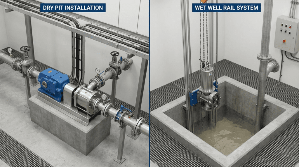
This article serves as a technical resource for municipal and industrial engineers tasked with designing or retrofitting pumping systems. We will explore where this technology fits—specifically comparing traditional dry pit installations against the growing trend of replacing rail-mounted submersible pumps with suction-lift rotary lobe configurations. By understanding the specific hydraulic and mechanical requirements of rotary lobe pumps, engineers can reduce lifecycle costs, eliminate dangerous ragging incidents, and improve overall plant reliability.
How to Select and Specify Rotary Lobe Systems
Successful implementation of Rotary Lobe Installation Best Practices (Wet Well Dry Pit and Rail Systems) begins with a specification that acknowledges the unique physics of positive displacement pumping. Unlike centrifugal pumps, where head determines flow, in a rotary lobe pump, speed determines flow, and the system resistance determines the pressure generation (up to the motor’s torque limit). This distinction dictates every aspect of selection.
Duty Conditions & Operating Envelope
Defining the operating envelope for a rotary lobe pump requires more than just a single duty point (GPM @ TDH). Because slip (internal leakage) varies with viscosity and differential pressure, the specification must account for the full range of fluid characteristics.
- Viscosity Variability: In sludge applications, viscosity is non-Newtonian and thixotropic. A pump sized for 2% solids may cavitate or experience excessive slip if the process changes to 6% solids. Specifications should define a viscosity range (e.g., 1 cP to 5,000 cP) to ensure the motor is sized for the highest torque requirement (high viscosity) and the speed is capable of overcoming slip at the lowest viscosity.
- Solids Passage: While rotary lobes can pass solids, the maximum particle size is limited by the gap between the lobe and the housing. Specifications must explicitly state the maximum sphere size required. Typical municipal allowances range from 1.5″ to 4.0″ depending on pump size.
- Rotational Speed (RPM): This is the primary driver of wear. For abrasive applications (grit chambers, primary sludge), lower speeds (typically <250 RPM) significantly extend lobe life. Specifications should limit maximum RPM based on fluid abrasiveness, not just hydraulic capacity.
Materials & Compatibility
The interaction between the rotor (lobe) material and the pump housing is critical. Unlike the metal-on-metal clearance of a centrifugal wear ring, rotary lobes often utilize elastomeric coatings that seal against a metal housing.
- Elastomer Selection: NBR (Nitrile) is standard for municipal wastewater, offering good resistance to fats, oils, and greases. EPDM is generally avoided in municipal wastewater due to poor oil resistance but may be used in specific industrial chemical applications. FKM (Viton) is reserved for high-temperature or aggressive chemical industrial effluents.
- Housing Hardness: To prevent the “washing out” of the housing due to grit, the housing segments (often replaceable wear plates) should be significantly harder than the anticipated abrasives. Hardened steel or ceramic-coated wear plates are recommended for primary sludge or grit applications.
- Chemical Compatibility: If the pump will be used for CIP (Clean-In-Place) or chemical dosing (e.g., polymer injection), the lobe core and shaft seals must be compatible with the cleaning agents, not just the process fluid.
Hydraulics & Process Performance
The hydraulic selection focuses heavily on Net Positive Suction Head (NPSH). This is the area where Rotary Lobe Installation Best Practices (Wet Well Dry Pit and Rail Systems) diverge most sharply.
In a Wet Well Dry Pit (WWDP) scenario with flooded suction, NPSH available (NPSHa) is usually sufficient. However, losses through valves and elbows immediately upstream of the pump must be minimized to ensure the pump chamber fills completely during each rotation.
In Suction Lift scenarios (often replacing rail-mounted submersibles), the calculation is critical. Rotary lobe pumps are self-priming, typically up to 25 feet (wet). However, as suction lift increases, the pump’s volumetric efficiency decreases due to the expansion of entrained gases (air/methane) in the suction line. Engineers must derate the pump capacity for high-lift applications.
Installation Environment & Constructability
The physical footprint of rotary lobe pumps allows for flexible installation strategies, but access for maintenance is paramount.
- Maintenance in Place (MIP): The design should allow the front cover to be removed and lobes replaced without disconnecting the suction or discharge piping. Ensure there is at least 3-4 feet of clearance in front of the pump cover in the layout drawings.
- Piping Loads: Unlike robust ANSI pumps, rotary lobe pump casings can distort under heavy pipe strain, leading to rotor-to-housing contact. Expansion joints or flexible connectors are mandatory on both suction and discharge flanges to isolate the pump from piping stresses.
- Baseplates and Rails: In dry pits, pumps should be mounted on concrete plinths to elevate them for ergonomic maintenance. For “rail system” retrofits where a lobe pump sits above a wet well, the baseplate should span the opening securely, often requiring custom steel fabrication to match the existing hatch dimensions.
Reliability, Redundancy & Failure Modes
Reliability in PD pumps is a function of seal integrity and pressure protection. The most common failure mode is seal failure allowing sludge into the bearing housing (timing gear chamber).
- Intermediary Chamber: Specify a “quench” or buffer chamber between the pump seal and the gearbox. This allows operators to visually inspect for seal leakage (via a sight glass or level sensor) before the fluid contaminates the expensive gearbox oil.
- Dry Run Protection: While rotary lobes can tolerate brief dry periods, prolonged dry running destroys elastomers. Temperature sensors on the housing or flow switches on the discharge are critical interlocks.
- Pressure Relief: A rotary lobe pump working against a closed valve will continue to build pressure until a shaft breaks, a pipe bursts, or the motor stalls. A dedicated pressure relief valve (PRV) or rupture disc in the discharge line, coupled with electronic high-pressure torque cut-outs, is mandatory.
Lifecycle Cost Drivers
While the Capital Expenditure (CAPEX) for a rotary lobe pump can be higher than a comparable centrifugal pump, the Operational Expenditure (OPEX) often favors the lobe pump in sludge applications.
- Energy Efficiency: At high viscosities (>500 cP), rotary lobe pumps maintain high efficiency (70-85%), whereas centrifugal pump efficiency plummets.
- Consumables: Lobes and wear plates are consumables. The cost of a lobe set and the frequency of replacement (typically 2-5 years depending on grit) should be factored into the Total Cost of Ownership (TCO).
- Labor: The ability to change lobes in under an hour without a hoist or confined space entry (in suction lift applications) significantly reduces labor costs compared to pulling a heavy submersible pump from a rail system.
Comparison Tables
The following tables provide a structured comparison to assist engineers in selecting the right technology and understanding the nuances of different installation configurations. These objective comparisons focus on engineering constraints rather than marketing highlights.
Table 1: Technology Comparison for Sludge Applications
| Feature / Parameter | Rotary Lobe Pump | Non-Clog Centrifugal | Progressive Cavity (PC) |
|---|---|---|---|
| Handling of Solids/Rags | Excellent. Positive displacement action passes rags; cutters can be integrated. | Good, but prone to “ragging” on the impeller leading edge without chopper features. | Good for small solids, but rags can wrap around the rotor/stator connecting rod. |
| Viscosity Capability | High. Efficiency improves with viscosity. Ideal for thickened sludge (4-8%). | Low. Performance degrades rapidly as viscosity increases. Best for <1-2% solids. | Very High. The standard for dewatered cake or extremely viscous polymers. |
| Dry Run Capability | Moderate. Can run dry for minutes if seals are flushed/quenched. | Low to Moderate. Depends on seal design and fluid presence. | Zero. Stator burns out almost instantly without lubrication. |
| Maintenance Footprint | Compact. “Maintenance in Place” (MIP) allows front access. | Large. Often requires “back pull-out” or hoisting the unit. | Long. Requires significant space to pull the rotor out of the stator. |
| Flow Control | Linear. Flow is directly proportional to RPM. Precise metering. | Non-Linear. Highly sensitive to head pressure changes. | Linear. Very precise metering capability. |
Table 2: Installation Application Fit Matrix
| Application Scenario | Wet Well Dry Pit (Flooded Suction) | Suction Lift (Above Wet Well) | Rail System (Submersible) |
|---|---|---|---|
| Definition | Pump installed in a dry room below the water level of the adjacent wet well. | Pump installed at grade/top of tank; lifts fluid via suction pipe. | Pump submerged in fluid on guide rails (Note: Rare for Lobes, standard for Centrifugal). |
| Priming Requirement | None (Gravity feed). | Self-priming required (NPSHa must be checked). | None (Submerged). |
| Maintenance Access | Excellent (Walk-around access). Requires ventilation/safety checks. | Superior (Open air, no confined space). Easy visual inspection. | Poor. Requires hoist/crane to retrieve pump for any inspection. |
| Risk of Flooding | High. Dry pit can flood, damaging motors. | None. Equipment is above grade. | N/A (Designed to be flooded). |
| Retrofit Complexity | High. Requires civil work if pit doesn’t exist. | Low. Can bolt to existing hatch cover; drop suction pipe down. | Moderate. Guide rails usually specific to pump manufacturer. |
Engineer & Operator Field Notes
Real-world experience often diverges from the idealized conditions in a catalog. The following sections highlight practical considerations for Rotary Lobe Installation Best Practices (Wet Well Dry Pit and Rail Systems) gathered from plant startups and long-term operation records.
Commissioning & Acceptance Testing
During the Factory Acceptance Test (FAT) and Site Acceptance Test (SAT), verification of the gap tolerances is critical. Rotary lobe efficiency depends on the tight clearance between the lobes and the housing. If these gaps are too large, slip increases; if too small, thermal expansion can cause seizure.
- Verification of Clearances: Use feeler gauges to verify radial and axial clearances against the manufacturer’s data sheet before the first run.
- Rotation Check: Unlike centrifugals where reverse rotation just reduces flow, reverse rotation in a lobe pump reverses the flow direction entirely. Ensure the relief valve is on the correct side (discharge) relative to the rotation.
- Vibration Baseline: Establish a vibration baseline. High-frequency vibration often indicates cavitation (NPSH issue), while low-frequency “thumping” usually indicates pipe strain or misalignment.
Common Specification Mistakes
One of the most frequent errors in specifying rotary lobe pumps for rail system replacements is ignoring the suction pipe diameter. Engineers often match the pump flange size (e.g., 4-inch) to the suction pipe.
In suction lift applications, the suction pipe should almost always be one size larger than the pump inlet to reduce friction losses and maximize NPSHa. A 4-inch pump should typically have a 6-inch suction line when lifting sludge more than 10-15 feet.
O&M Burden & Strategy
For maintenance supervisors, the “Maintenance in Place” feature is the primary advantage. A standard PM schedule should include:
- Weekly: Check quench fluid level and color. Milky fluid indicates a mechanical seal breach.
- Monthly: Check gearbox oil level and inspect for localized heat buildup (bearing issues).
- Annually: Open front cover. Inspect lobe tips for abrasion. Inspect wear plates. If lobe wear is uneven, check piping alignment.
Troubleshooting Guide
If a rotary lobe pump fails to prime in a suction lift application, the culprit is rarely the pump itself.
- Air Leaks: Even a pinhole leak in the suction pipe prevents the vacuum required to lift sludge.
- Face Clearance: As lobes wear, the internal slip increases. Eventually, the slip becomes greater than the air displacement capability, and the pump loses its self-priming ability. Tightening the tolerances or replacing lobes usually solves this.
Design Details and Calculations
Proper sizing guarantees the longevity of the installation. The following methodologies apply to both dry pit and suction lift configurations.
Sizing Logic & Methodology
Sizing a rotary lobe pump involves calculating the required displacement volume ($V_d$) per revolution while accounting for slip ($Q_{slip}$).
$$ Q_{actual} = (V_d times RPM) – Q_{slip} $$
Where $Q_{slip}$ is a function of viscosity ($mu$), differential pressure ($Delta P$), and internal clearances. Manufacturers provide slip curves, but engineers should apply a safety factor.
- Determine Flow & Head: Calculate Total Dynamic Head (TDH) including static lift and friction losses. Convert TDH to PSI (TDH / 2.31 * SG).
- Select Speed: Choose a pump model that delivers the required flow at a conservative RPM (e.g., 200-350 RPM for sludge).
- Calculate Slip Correction: Using the manufacturer’s curves, estimate slip at the operating pressure and lowest expected viscosity. Increase RPM to compensate.
- Motor Sizing: Calculate Brake Horsepower (BHP).
$$ BHP = frac{Q times Delta P}{1714 times eta_{vol} times eta_{mech}} $$
Note: Starting torque for PD pumps is high. Ensure the motor and VFD are rated for “Constant Torque” loads, not “Variable Torque.”
Standards & Compliance
When creating bid documents, reference the following to ensure quality:
- API 676: While an oil & gas standard, it provides excellent guidelines for Positive Displacement pumps.
- HI 3.1-3.5: Hydraulic Institute standards for Rotary Pumps (Nomenclature, Definitions, Application, and Operation).
- ISO 9001: Ensure the manufacturer operates under a quality management system.
Frequently Asked Questions
What is the difference between a rotary lobe pump and a progressive cavity pump?
Both are positive displacement pumps used for sludge. A rotary lobe pump uses two counter-rotating lobes and is generally more compact, reversible, and easier to maintain in place (MIP). A progressive cavity (PC) pump uses a single helical rotor inside a rubber stator. PC pumps are better for metering and extremely high pressures but require a much larger footprint and are more difficult to service (often requiring the pump to be dismantled). Rotary lobe pumps are increasingly replacing PC pumps where space and maintenance speed are priorities.
How much suction lift can a rotary lobe pump handle?
Rotary lobe pumps can typically handle suction lifts up to 20-25 feet of water (wet prime). However, practically speaking, engineers should limit suction lift to 15 feet for sludge applications to avoid cavitation and reduced volumetric efficiency caused by entrained gases expanding under vacuum. For lifts greater than 15 feet, a flooded suction (dry pit) or a submersible solution is recommended.
Can rotary lobe pumps run dry?
Rotary lobe pumps have a limited dry-run capability compared to PC pumps, which fail almost instantly. If equipped with a flushed seal arrangement or an oil quench buffer, a rotary lobe pump can run dry for short periods (10-30 minutes) without catastrophic failure. However, continuous dry running will generate heat that destroys the elastomeric lobes. Installations should always include thermal protection or flow switches.
What are the best practices for rotary lobe installation in a wet well retrofit?
When replacing a rail-mounted submersible with a rotary lobe pump, the best practice is to mount the pump at grade (top of the wet well) on a fabricated skid that covers the existing hatch. A suction pipe is then dropped down into the wet well. This converts the system to a “suction lift” application. Critical steps include sizing the suction pipe one size larger than the pump inlet to minimize friction, installing a foot valve (if necessary, though lobes are self-priming), and ensuring the discharge piping is isolated from the pump via expansion joints.
Why is a VFD required for rotary lobe pumps?
A Variable Frequency Drive (VFD) is virtually mandatory for rotary lobe pumps for two reasons. First, it allows for flow control; since flow is linear with speed, a VFD provides precise process control. Second, and more importantly, it offers torque protection. The VFD can be programmed to trip if the torque exceeds a safe limit (indicating a blockage or closed valve), protecting the pump shaft and piping from damage.
How long do rotary lobes last in wastewater service?
In typical municipal sludge service (WAS/RAS), elastomer lobes usually last between 2 to 5 years. In abrasive primary sludge or grit applications, life may be reduced to 1-2 years. Hardened steel or other metallic lobes can be used for extreme abrasion but sacrifice some sealing efficiency (slip). The use of replaceable wear plates in the housing significantly extends the life of the main pump casing.
Conclusion
- Don’t Overspeed: Keep RPM below 300 for sludge applications to maximize wear life.
- Mind the Gap: Efficiency relies on tight tolerances; specify adjustable housings or replaceable wear plates.
- NPSHa is King: In suction lift retrofits, oversize the suction piping to maximize available NPSH.
- Protect the System: Always install pressure relief valves and torque-monitoring controls; PD pumps do not have a shut-off head like centrifugals.
- Maintenance Access: Ensure 3-4 feet of frontal clearance for “Maintenance in Place” (MIP).
Rotary lobe technology offers a robust, compact, and maintenance-friendly alternative to traditional centrifugal and progressive cavity pumps, particularly in high-solids wastewater applications. However, the successful deployment of Rotary Lobe Installation Best Practices (Wet Well Dry Pit and Rail Systems) relies on a fundamental understanding of positive displacement physics.
Engineers must carefully evaluate the hydraulic conditions—specifically suction lift limitations and viscosity variations—before selection. Whether designing a new dry pit facility or retrofitting a rail-mounted station with a surface-mounted unit, the focus must remain on conservative speed selection, robust material compatibility, and comprehensive system protection. By following these guidelines, utilities can achieve a high-reliability pumping system that reduces operator burden and minimizes long-term ownership costs.