Diaphragm Seal Failures: Causes
Introduction
In municipal water and industrial wastewater treatment facilities, pressure instrumentation is the sensory nervous system of the process. Yet, a surprising number of process upsets, pump protection failures, and chemical dosing errors can be traced back to a single, often overlooked component: the diaphragm seal (or chemical seal). Engineers frequently treat these isolation devices as commodities, yet the consequences of misapplication are costly. A ruptured diaphragm in a sodium hypochlorite feed line not only destroys a $2,000 pressure transmitter but can also create a hazardous chemical leak and shut down disinfection processes.
Diaphragm seals are critical interfaces used to isolate pressure measuring instruments—gauges, switches, and transmitters—from harsh process media. In the water sector, they are ubiquitous in sludge lines, chemical dosing skids, and high-solids wastewater streams. Understanding Diaphragm Seal Failures: Causes and prevention strategies is essential for ensuring reliable plant automation and reducing operational expenditures (OPEX).
This article provides a deep technical dive into why these components fail, moving beyond basic symptoms to root cause analysis. We will explore the physics of fill fluid expansion, the metallurgy of corrosion resistance, and the mechanical stresses of water hammer. By focusing on proper specification and lifecycle management, engineers and plant superintendents can significantly improve system reliability.
How to Select and Specify for Reliability
Preventing failure begins at the specification stage. Many Diaphragm Seal Failures: Causes can be directly attributed to a mismatch between the process conditions and the seal construction. Engineers must evaluate the operating envelope comprehensively rather than simply copying previous specifications.
Duty Conditions & Operating Envelope
The primary driver for seal selection is the pressure profile of the application. Engineers must consider not just the static working pressure, but dynamic conditions:
- Vacuum Service: This is a common blind spot. On the suction side of pumps or in vacuum priming systems, negative pressure can cause the fill fluid to outgas or boil if not properly selected. This creates bubbles behind the diaphragm, leading to measurement drift or “ballooning” of the diaphragm.
- Overpressure and Spikes: In wastewater force mains, water hammer is prevalent. Standard diaphragms have limited overpressure protection. If the pressure spike exceeds the diaphragm’s elastic limit, permanent deformation occurs, rendering the instrument inaccurate.
- Pulsation: Reciprocating positive displacement pumps (metering pumps) create high-frequency pulsations. Without internal damping or proper seal sizing, the constant cycling leads to metal fatigue and eventual cracking of the diaphragm material.
Materials & Compatibility
Chemical incompatibility is a leading cause of failure. The wetted parts (lower housing and diaphragm) must be compatible with the process media. In water and wastewater, standard 316 Stainless Steel is often insufficient.
- Corrosion: Ferric Chloride and Sodium Hypochlorite are highly aggressive. Hypochlorite, for instance, attacks stainless steel rapidly through pitting and crevice corrosion. Tantalum or Titanium diaphragms are often required for these services.
- Hydrogen Permeation: In certain galvanic conditions or specific chemical reactions, atomic hydrogen can form on the surface of the diaphragm. Because hydrogen atoms are small enough to pass through the metal lattice of certain alloys, they can permeate the diaphragm and recombine into molecular hydrogen (gas) inside the fill fluid chamber. This gas buildup distorts the diaphragm, causing a drift in zero reading and eventually total failure. Gold plating the diaphragm is a common specification strategy to prevent this permeation.
- Abrasion: In grit removal systems or raw sewage sludge, abrasive particles can wear down soft metal diaphragms. High-strength alloys or coated diaphragms may be necessary.
Hydraulics & Process Performance
The diaphragm seal system acts as a hydraulic transmission line. The pressure exerted on the diaphragm compresses the fill fluid, which transmits the force to the sensing element. This hydraulic relationship introduces performance constraints:
- Response Time: High-viscosity fill fluids (like Glycerin) in cold climates (outdoor lift stations) will slow down the response time. In critical control loops, such as discharge pressure control on VFD pumps, this lag can cause oscillation or instability.
- Temperature Error: The fill fluid expands and contracts with ambient temperature changes. If the total volume of fluid is large (e.g., long capillary tubes) and the diaphragm is small (low displacement), a rise in ambient temperature can create significant internal pressure, known as temperature error.
Installation Environment & Constructability
Physical access and environmental protection play a role in longevity. Specifications should address:
- Vibration: If the measurement point is on a vibrating pump discharge, direct-mounting the instrument can damage the transmitter electronics. Using a capillary line to remote-mount the transmitter away from the vibration source is a best practice.
- Heat Tracing: For outdoor installations in freezing climates, the fill fluid and the process media in the stagnant leg can freeze. Engineers must specify heat tracing compatibility or integral heating jackets.
Reliability, Redundancy & Failure Modes
Understanding the Mean Time Between Failures (MTBF) aids in planning. The most common failure mode is diaphragm rupture, followed by fill fluid leakage. For critical regulatory monitoring points (e.g., effluent turbidity or final system pressure), redundancy is key. Engineers should specify “smart” transmitters that can detect diagnostic alerts, such as blocked impulse lines or sensor drift, before a total failure occurs.
Controls & Automation Interfaces
The seal must interact correctly with the control system (SCADA). If a diaphragm is damaged and biased +10 psi, the VFD may ramp down the pump erroneously. Specifications should require instruments with adjustable damping and scaling to account for the hydraulic characteristics of the seal system.
Maintainability, Safety & Access
Maintenance teams need the ability to clean and inspect the seal without dismantling the entire piping system.
- Flushing Rings: For wastewater sludge and fluids containing solids, a flushing ring (or calibration ring) is mandatory. It is sandwiched between the process flange and the seal, featuring ports that allow operators to flush out accumulated solids without removing the seal.
- Isolation Valves: Always specify a root valve to allow for removal of the instrument assembly under pressure (lockout/tagout procedures still apply).
Lifecycle Cost Drivers
While a seal with a Tantalum diaphragm and a flushing ring costs significantly more than a standard 316SS off-the-shelf unit, the lifecycle analysis must consider the cost of downtime, the labor to replace failed units, and the cost of inaccurate chemical dosing. A $500 savings on CAPEX often translates to $5,000 in additional OPEX over five years due to frequent replacements.
Diaphragm Seal Comparison and Selection Matrices
The following tables provide a comparative analysis of materials and fill fluids to assist engineers in minimizing Diaphragm Seal Failures: Causes related to chemical attack and thermal expansion. These guides are general; always consult the manufacturer’s specific chemical resistance charts.
Table 1: Wetted Material Compatibility Guide
| Material | Primary Strengths | Best-Fit Applications | Limitations/Weaknesses | Relative Cost |
|---|---|---|---|---|
| 316L Stainless Steel | General corrosion resistance, high availability, ruggedness. | Potable water, raw sewage, non-corrosive sludge, air lines. | Fails rapidly in Sodium Hypochlorite, Ferric Chloride, and Hydrochloric Acid. | Low |
| Hastelloy C-276 | Excellent resistance to localized corrosion and stress corrosion cracking. | Sulfuric Acid, aggressive wastewater, sour gas, seawater. | Not suitable for strongest oxidizers; more expensive than SS. | Medium |
| Tantalum | Superior resistance to almost all acids and corrosive salts. Comparable to glass. | Sodium Hypochlorite, Ferric Chloride, Hydrochloric Acid, Chlorine Gas. | Soft metal (susceptible to physical damage/abrasion); reacts with Sodium Hydroxide and Hydrofluoric Acid. | High |
| Monel 400 | Excellent resistance to hydrofluoric acid and seawater. | Brackish water reverse osmosis, specific acid feeds. | Susceptible to pitting in stagnant seawater; not for oxidizing acids. | Medium-High |
| PTFE (Teflon) Coated | Non-stick, high chemical resistance. | Sticky sludge, polymer feed (prevents buildup). | Coating can peel or scratch; limits temperature range and response time. | Medium |
Table 2: Fill Fluid Selection Matrix
| Fill Fluid Type | Typical Temp Range | Vacuum Suitability | Application Notes | Risk Factors |
|---|---|---|---|---|
| Silicone Oil (Standard) | -40°F to 400°F | Good | The industry standard for general water/wastewater applications. | Cannot be used where silicone contamination is prohibited (rare in WW, common in paint/coating plants). |
| Glycerin / Water | 15°F to 200°F | Poor | Food grade applications or where silicone is banned. | Freezes easily; not suitable for outdoor lift stations in cold climates. High viscosity slows response. |
| Halocarbon | -40°F to 300°F | Excellent | Oxygen or Chlorine service where flammability is a concern. Inert. | Expensive. High density affecting head pressure calibration. |
| Syltherm / High-Temp Silicone | -40°F to 600°F+ | Good | Incinerator processes, thermal drying systems. | Lower viscosity; potential for leakage at connections if not torqued correctly. |
Engineer and Operator Field Notes
Real-world experience often deviates from the catalog data. The following insights focus on mitigating Diaphragm Seal Failures: Causes during commissioning, operation, and troubleshooting.
Commissioning & Acceptance Testing
The transition from construction to operation is the most dangerous time for diaphragm seals.
- The Zero Shift: It is standard for diaphragm seals to exhibit a “zero shift” after installation due to the tightening of bolts or changes in orientation. Pro Tip: Always zero the transmitter or gauge after it has been installed and torqued into place, but before the process pressure is applied.
- Position Sensitivity: If a transmitter is remote-mounted via capillary, the height difference between the seal and the instrument creates a head pressure error. For every ~1 inch of elevation difference (depending on fill fluid density), a predictable error is introduced. This must be calibrated out during commissioning.
- Vacuum Filling Verification: High-quality seals are vacuum filled to remove all air. If the instrument response feels “spongy” or exhibits significant hysteresis during SAT (Site Acceptance Testing), it suggests air entrapment in the fill fluid. The unit should be rejected and returned to the factory.
Common Specification Mistake: Specifying a “standard” range (e.g., 0-100 psi) without checking the minimum span of the diaphragm seal. Large diaphragms are needed to drive low-pressure ranges. Using a small 1/2″ diaphragm seal for a 0-5 psi application will result in poor accuracy and high temperature drift.
O&M Burden & Strategy
Maintenance for diaphragm seals is largely preventive.
- Visual Inspection: Operators should inspect seals annually for physical damage. Look for “dimpling” on the diaphragm surface, which indicates solids impact or overpressure.
- Flushing Schedule: For sludge lines, establish a flushing interval (e.g., quarterly). Use the flushing ring ports to clear out sediment that packs between the diaphragm and the process flange. Packed sediment stiffens the sensing area, causing the instrument to read lower than actual pressure.
- Heat Trace Checks: In the fall, verify that heat tracing on capillary lines is functional. A frozen capillary will lock the pressure reading at the last value before freezing, misleading operators into thinking the pressure is stable.
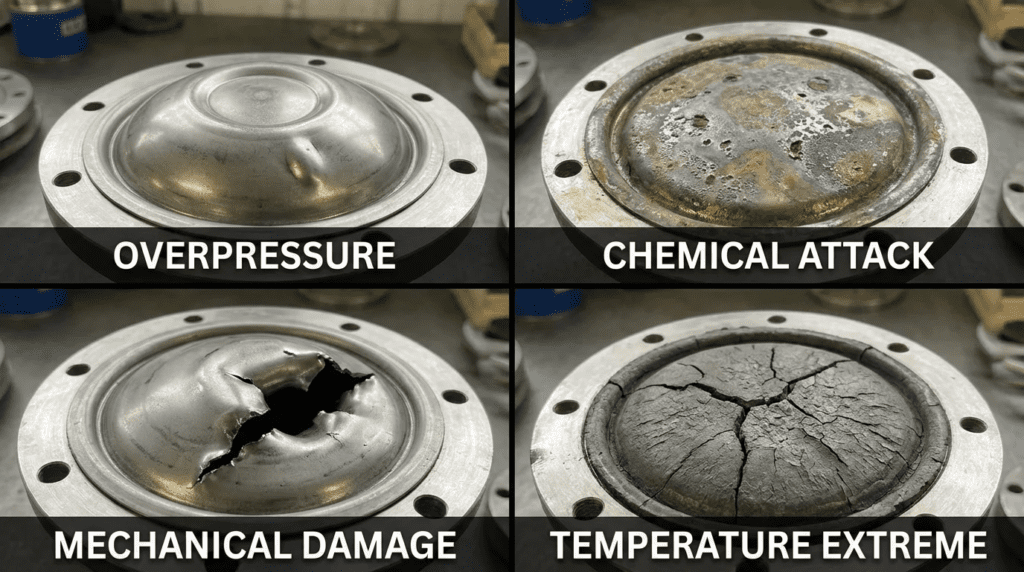
Troubleshooting Guide: Diagnosing Failure
When an instrument fails, the failure mode of the seal often tells the story:
- Symptom: Reading Drifts with Ambient Temperature.
Root Cause: System volume is too high for the diaphragm stiffness (Temperature Error). Or, the capillary lines are exposed to direct sunlight causing uneven heating.
Fix: Shade the capillaries or switch to a seal with a larger diaphragm diameter to absorb expansion. - Symptom: Instrument Reads Zero or Atmospheric Pressure constantly.
Root Cause: Diaphragm rupture. The fill fluid has leaked into the process, and the process fluid has likely entered the instrument.
Fix: Replace the assembly. Investigate for chemical attack or water hammer. - Symptom: Diaphragm is Puffed Out (Ballooned).
Root Cause: Hydrogen permeation or vacuum damage. Gas has built up behind the diaphragm.
Fix: If hydrogen permeation, specify Gold-plated diaphragm. If vacuum, ensure fill fluid is rated for vacuum service.
Design Details: Sizing and Specification Logic
To systematically eliminate Diaphragm Seal Failures: Causes, engineers must apply specific sizing logic during the design phase.
Sizing Logic & Methodology: Temperature Error (TE)
One of the most complex aspects of diaphragm seal engineering is calculating the temperature error. The fill fluid expands as temperature rises ($V_t = V_0(1 + beta Delta T)$). Since the system is sealed, this expansion exerts pressure on the diaphragm. The stiffer the diaphragm, the higher the pressure error.
Design Rule of Thumb:
The larger the diaphragm diameter, the lower the temperature error.
A 3-inch diaphragm is significantly more flexible than a 1.5-inch diaphragm. For low-pressure applications (< 15 psi), always prioritize larger diaphragm faces (3-inch or 4-inch) to minimize drift.
Specification Checklist
When writing the instrumentation specification (Section 40 91 00), ensure these items are explicitly defined:
- Process Connection: Threaded, Flanged (ANSI class), or Sanitary (Tri-Clamp).
- Diaphragm Material: Default to 316L, but specify Hastelloy or Tantalum for chemical feeds.
- Fill Fluid: Silicone is standard; ensure it matches the temperature range.
- Flushing Ring: Mandatory for wastewater/sludge. Specify material to match the diaphragm.
- Capillary Length: Keep as short as possible to minimize temperature error and response lag.
- Lower Housing Material: This flange or housing touches the process. It must be as corrosion-resistant as the diaphragm.
- Mounting Hardware: Stainless steel bolts are required for corrosive environments.
Standards & Compliance
- ASME B40.100: The governing standard for pressure gauges and attachments.
- NACE MR0175 / ISO 15156: Required for “sour” environments containing Hydrogen Sulfide ($H_2S$), common in raw sewage and digester gas applications. Ensures materials resist sulfide stress cracking.
- CRN (Canadian Registration Number): Required for pressure fittings in Canadian provinces.
Frequently Asked Questions
What are the primary Diaphragm Seal Failures: Causes in wastewater treatment?
The most common causes in wastewater are physical obstruction (solids packing against the diaphragm), chemical corrosion (using 316SS for ferric or hypo), and mechanical damage from water hammer in force mains. Additionally, failure to account for vacuum conditions on pump suction lines often leads to fill fluid outgassing and diaphragm deformation.
When should I use a flushing ring with a diaphragm seal?
A flushing ring should be used whenever the process media contains suspended solids, sludge, or viscous materials that could clog the process connection. In wastewater plants, this includes raw sewage, primary sludge, RAS/WAS lines, and polymer feed systems. The ring allows maintenance staff to flush the cavity without removing the instrument from the process line.
How does temperature affect diaphragm seal accuracy?
Temperature changes cause the fill fluid inside the seal system to expand or contract. This volume change creates an internal pressure that the instrument reads as a process pressure change. This is called “Temperature Error.” It is most severe in low-pressure applications (below 15 psi) or systems with long capillary tubes. Using larger diaphragms helps mitigate this effect.
What is the difference between a diaphragm seal and a chemical tee?
A diaphragm seal isolates the instrument completely using a flexible membrane and fill fluid. A chemical tee is simply a pipe fitting (often PVC or CPVC) with a threaded port for an instrument. A chemical tee offers no isolation; the instrument’s wetted parts are in direct contact with the process. Diaphragm seals are required when the process fluid would corrode or clog a standard instrument.
Why do diaphragm seals fail in Sodium Hypochlorite applications?
Sodium Hypochlorite is an aggressive oxidizer that causes pitting and crevice corrosion in 316 Stainless Steel. Furthermore, off-gassing of the chemical can occur. The primary failure mode is corrosion-induced rupture. Engineers should specify Tantalum or heavy-duty Titanium diaphragms and wetted parts for Hypochlorite service to ensure longevity.
Can I repair a failed diaphragm seal?
generally, no. While the instrument (transmitter or gauge) might be salvageable, the diaphragm seal itself is a welded, vacuum-filled assembly. Once the diaphragm is ruptured or permanently deformed, the entire seal assembly usually requires replacement. Some manufacturers offer “replaceable” bottom housings, but the upper sealed unit is disposable.
Conclusion
Key Takeaways for Engineers
- Match Materials to Chemistry: Never assume 316SS is “good enough.” Use Tantalum for Hypochlorite and Hastelloy for strong acids.
- Manage the Solids: Always specify flushing rings for sludge and raw sewage applications to prevent clogging.
- Beware of Vacuum: Verify the fill fluid and seal construction can withstand full vacuum if installed on pump suction lines.
- Size for Temperature: Use larger diaphragms (3″ or 4″) for low-pressure applications to minimize thermal drift.
- Protect Against Spikes: Water hammer is a diaphragm killer. Ensure the seal has overpressure protection or the system includes surge relief.
Analyzing Diaphragm Seal Failures: Causes reveals that the vast majority of issues are preventable through rigorous specification and application engineering. The diaphragm seal is a small component with a disproportionate impact on plant reliability. By moving away from generic “boiler-plate” specifications and actively evaluating the chemical, physical, and thermal constraints of each measuring point, engineers can dramatically reduce maintenance intervals and improve process data integrity.
For municipal and industrial decision-makers, the investment in high-quality, application-specific isolation devices yields returns through accurate control, reduced chemical waste, and minimized operator exposure to hazardous fluids. When in doubt, consult with the instrumentation manufacturer’s engineering team to validate the compatibility of the seal design with the specific process conditions.