Rotary Lobe Clogging and Ragging: How to Reduce Blockages
Introduction
The operational landscape of municipal and industrial wastewater treatment has shifted dramatically over the last two decades. The influx of non-dispersible fibrous materials—commonly referred to as “flushable” wipes, synthetic rags, and hair accumulations—has created a chronic reliability crisis for positive displacement pumping equipment. For engineers designing sludge transfer systems or primary clarification wasting circuits, the challenge of Rotary Lobe Clogging and Ragging: How to Reduce Blockages has become a central design constraint rather than a secondary maintenance nuisance.
Industry data suggests that unplanned maintenance due to pump ragging costs utilities billions annually in labor, equipment wear, and energy inefficiencies. While rotary lobe pumps are favored for their compact footprint, ability to run dry for short periods, and maintenance-in-place (MIP) capabilities, their interacting rotor design can make them susceptible to wrapping and binding when exposed to modern waste streams. Unlike centrifugal pumps, which may pass solids through a large volute, rotary lobe pumps rely on tight clearances to maintain volumetric efficiency. When fibrous solids invade these clearances, they do not merely reduce flow; they can torque-out the drive, damage mechanical seals, and compromise the timing gears.
Common engineering oversight often attributes clogging solely to the pump’s internal geometry. However, effective mitigation requires a holistic approach involving upstream protection, material selection, smart control logic, and precise hydraulic sizing. This article provides a technical framework for engineers to specify rotary lobe systems that resist fouling, ensuring process continuity in high-rag environments.
How to Select and Specify for Ragging Mitigation
Addressing Rotary Lobe Clogging and Ragging: How to Reduce Blockages begins during the specification phase. A standard off-the-shelf lobe pump specified for “water-like” fluids will fail rapidly in primary sludge or thickened waste activated sludge (TWAS) applications containing fibrous debris.
Duty Conditions & Operating Envelope
The interaction between fluid velocity and rotor speed is critical in ragging mitigation. While low shear is a selling point for rotary lobe pumps (especially to preserve floc in sludge), operating at extremely low RPMs can be detrimental regarding ragging. At very low speeds, there is insufficient inertia to clear minor accumulations, allowing rags to wrap around the lobes rather than passing through.
Engineers must define the operating envelope to avoid the “dead zone” where solids settle in the pump chamber. Specifications should require performance curves that indicate minimum stable speeds for solids passage, not just hydraulic movement. Additionally, duty cycles must be considered; intermittent operation allows solids to dewater and harden within the pump chamber during downtime, increasing the likelihood of startup torque faults. If the pump is for intermittent duty, specify a flush cycle or a “soft start/cleaning” algorithm.
Materials & Compatibility
Standard NBR (Nitrile Butadiene Rubber) or EPDM coated lobes are common for their ability to seal tightly and handle grit. However, rubber lobes have a high coefficient of friction against dry fibrous material. When a rag enters the nip point, rubber tends to grip the rag, facilitating wrapping.
For high-rag applications, consider specifying:
- Hardened Steel or Stainless Steel Rotors: Metal rotors provide a lower friction coefficient, allowing rags to slide off the profile rather than gripping and wrapping.
- Recessed or “Wiper” Designs: Some manufacturers offer metallic rotors with sharp, hardened edges designed to shear material against a wear plate, acting as a minor macerator within the pump head.
- Hardened Wear Plates: Replaceable radial and axial wear plates (often tungsten carbide coated) maintain efficiency even if abrasive grit accompanies the rags.
Hydraulics & Process Performance
Lobe geometry significantly influences ragging potential. The traditional bi-lobe or tri-lobe design creates large cavities, but the “pulsation” can sometimes facilitate rag balling. Advanced multi-lobe (helical) designs offer virtually pulsation-free flow, which creates a steady stream that helps carry solids through the discharge.
However, the most critical hydraulic factor is the Nip Point Protection. The converging space between the rotors is where ragging initiates. Engineers should evaluate pump designs that feature:
- Helical Rotors: The twisted profile pushes solids axially through the pump rather than trapping them radially.
- Large Solids Passage: Ensure the specified sphere size capability exceeds the expected agglomeration size, though this is difficult with stringy material.
Installation Environment & Constructability
A major contributor to Rotary Lobe Clogging and Ragging: How to Reduce Blockages is poor suction piping design. Turbulence at the pump inlet causes rags to twist into “ropes” before they even enter the pump chamber.
Installation best practices include:
- Maintaining straight pipe runs of 5-10 diameters upstream of the suction flange.
- Avoiding 90-degree elbows immediately at the inlet; use long-radius sweeps if necessary.
- Ensuring positive suction head (NPSHa > NPSHr) to prevent cavitation, as cavitation creates voids that fibrous materials can fill and expand into.
Reliability, Redundancy & Failure Modes
In high-rag services like Primary Sludge or RAS, redundancy is non-negotiable. However, standard “Duty/Standby” configurations can be problematic if the standby pump sits idle for weeks, allowing residual sludge to cement rags to the rotors. Specifications should mandate automatic alternation every 12-24 hours to keep both units active and clear.
Failure analysis shows that ragging often leads to shaft deflection. This deflection compromises the mechanical seal faces. Therefore, specifying robust bearing isolates and shorter shaft overhangs (L3/D4 ratios) improves the pump’s resilience to the radial loads caused by ragging events.
Controls & Automation Interfaces
This is arguably the most effective tool for modern engineering. The specification must include advanced VFD requirements. The control system needs to monitor torque (or current) at a high sampling rate. The “Anti-Ragging” sequence should be specified as follows:
- Drive detects amp/torque spike above baseline (e.g., 120% of nominal).
- Drive stops the pump immediately.
- Drive reverses direction for a set number of rotations (typically 3-5 revolutions) to unwind the obstruction.
- Drive stops and resumes forward motion.
- If the spike persists after 3 attempts, the VFD faults out and triggers a SCADA alarm.
Lifecycle Cost Drivers
While rotary lobe pumps often have a lower CAPEX than large progressing cavity pumps or plunger pumps, the OPEX regarding ragging can be severe. If an operator must manually de-rag a pump weekly, the labor cost (2 hours x 2 operators x 52 weeks) can exceed the pump cost in 3 years. Engineers must conduct a TCO analysis that penalizes designs lacking auto-reverse capabilities or requiring complex disassembly for cleaning.
Technology and Strategy Comparisons
The following tables provide an objective comparison of pumping technologies and mitigation strategies relevant to fibrous wastewater applications. These are intended to assist engineers in selecting the correct equipment configuration for specific facility constraints.
| Technology | Features relative to Ragging | Best-Fit Applications | Limitations/Considerations | Typical Maintenance Profile |
|---|---|---|---|---|
| Rotary Lobe (Standard Rubber Lobe) | High friction; susceptible to wrapping; tight clearances. | Thickened sludge; Polymer feed; Scum (macerated). | Not recommended for raw sewage or primary sludge without upstream grinding. | Frequent checks; lobes may need replacement if cut by debris; seal damage common if ragging causes deflection. |
| Rotary Lobe (Advanced Metal/Helical) | Shearing action; lower friction; axial solids movement. | Primary sludge; RAS/WAS; Digester feed. | Higher initial cost; reduced volumetric efficiency on thin liquids compared to rubber. | Lower frequency of blockages; wear plates require monitoring; generally robust. |
| Progressing Cavity (PC) | Can pass solids, but rags wrap around connecting rod/joint. Stator inlet blockage common. | Dewatering feed (constant pressure); High solids cake. | Large footprint; rag removal is difficult (often requires dismantling discharge). | Stator replacement is labor-intensive; expensive rotors; difficult to clear jams automatically. |
| Disc Pump / Vortex | Non-contact pumping; effectively immune to ragging inside the volute. | Raw sewage lift stations; Grit pumping; heavy rag environments. | Lower efficiency; limited pressure capabilities compared to PD pumps; not for metering. | Low maintenance; rarely clogs; impeller wear is minimal. |
| Electric Diaphragm | No rotating parts to wrap; check valves are the only choke point. | Lime slurry; Chemical metering; viscous sludge. | Pulsating flow; check valves foul easily with long rags; limited flow rates. | Diaphragm replacement; ball check cleaning required if rags prevent seating. |
| Application Scenario | Risk Level | Recommended Mitigation Strategy | Control Logic Necessity | Relative Cost Impact |
|---|---|---|---|---|
| Primary Sludge Transfer | High | In-line grinder/macerator + Metal Helical Lobes. | Critical (Auto-Reverse) | High (Grinder adds 30-50% cost) |
| RAS / WAS Pumping | Medium | Recessed Rotors or Helical Rubber Lobes. | Recommended | Medium |
| Digested Sludge | Low | Standard Rubber Lobes usually sufficient. | Optional | Low |
| Septage Receiving | Extreme | Rock Trap + Twin-Shaft Grinder + Metal Lobe Pump. | Critical | Very High (Complete headworks required) |
Engineer & Operator Field Notes
Real-world performance often deviates from theoretical curves. The following notes are compiled from field experience in commissioning and maintaining rotary lobe systems in difficult wastewater environments.
Commissioning & Acceptance Testing
The Factory Acceptance Test (FAT) typically uses clean water. While this verifies hydraulic performance and hydrostatic integrity, it does nothing to prove rag handling. For Site Acceptance Testing (SAT), engineers should enforce a “stress test.”
- Baseline Amperage: Establish the baseline amp draw with clean water and then with clean sludge.
- Simulated Fault: If possible, introduce fibrous material (if the system allows) to verify the VFD’s trip logic.
- Reverse Logic Verification: Manually trigger the reverse sequence to ensure the pump actually reverses. Note: Check that check valves on the discharge do not slam destructively during this rapid reversal.
Common Specification Mistakes
One of the most frequent errors in solving Rotary Lobe Clogging and Ragging: How to Reduce Blockages is Oversizing the Pump. Engineers often apply large safety factors, resulting in a pump that runs at 10-20% of its rated speed. At these low RPMs, the pump lacks the momentum to push a rag knot through the discharge port. The rag stays in the chamber, tumbling and gathering more debris until it locks the rotor.
Mistake 2: Ignoring the Grinder Interface. Specifying a grinder upstream is good, but if the grinder and pump are not interlocked, a grinder failure leads to the pump ingesting un-ground rags immediately. The controls must shut down the pump if the grinder alarms.
O&M Burden & Strategy
Operators should adopt a proactive approach to clearances. As lobes and wear plates erode, the “slip” increases. To maintain flow, the VFD speeds up. Higher speed can actually help clear rags, but the widened gap allows rags to get wedged between the lobe and housing, which causes severe scoring.
- Weekly: Monitor VFD trends. A rising torque trend at constant flow indicates internal fouling or bearing drag.
- Monthly: Inspect the quench fluid / barrier fluid. Contamination here indicates seal failure, often caused by shaft deflection from ragging events.
- Annually: Check timing gear backlash. Ragging events put immense stress on timing gears. If the timing slips, lobes will clash, causing catastrophic failure.
Troubleshooting Guide
- Symptom: High Amps, Low Flow.
Cause: Rag ball accumulation at the suction port or wrapped around rotors.
Action: Initiate reverse cycle. If unsuccessful, lock-out/tag-out and open front cover. - Symptom: Knocking Sound.
Cause: Cavitation (air binding) or timing gear slip. Rags can cause air binding by blocking the suction.
Action: Check suction gauge. If vacuum is high, the suction line is plugged (ragged). - Symptom: Frequent Seal Failure.
Cause: Shaft deflection due to solids jamming.
Action: Upgrade to harder shaft material or check bearing isolators.
Design Details and Sizing Logic
Proper sizing is the first line of defense against blockages. The goal is to select a unit that operates at a speed high enough to maintain self-cleaning velocities but low enough to prevent rapid abrasive wear.
Sizing Logic & Methodology
When sizing for rag-laden fluids, do not rely solely on the manufacturer’s clean water curve. You must account for “Slip” and “Solids Derating.”
Step 1: Determine Flow and Pressure. Calculate TDH carefully, including the friction losses of the thick sludge.
Step 2: Calculate Slip. Rotary lobe pumps have internal leakage (slip) that flows from discharge back to suction. Slip increases with pressure and decreases with viscosity. However, ragging acts like an artificial viscosity increase initially, then a blockage.
Equation (Simplified): $Q_{actual} = Q_{theoretical} – Q_{slip}$
Step 3: Select RPM. For sludge with rags, target an operating speed between 150 and 350 RPM.
– Below 100 RPM: High risk of rag wrapping.
– Above 400 RPM: High risk of abrasive wear and cavitation.
Step 4: Motor Sizing. Do not size the motor just for the hydraulic load. Size it for the Breakout Torque. When a pump has been sitting idle, or when it encounters a minor rag ball, it needs excess torque to push through. A 1.5 to 2.0 service factor on the required torque is standard engineering practice for waste sludge applications.
Specification Checklist
To ensure the equipment supplied mitigates Rotary Lobe Clogging and Ragging: How to Reduce Blockages, the specification must explicitly call out:
- Rotor Material: Hardened steel or bi-metal (unless chemical compatibility dictates otherwise).
- Housing Construction: Replaceable wear plates (axial and radial).
- Maintenance Access: “Maintenance in Place” (MIP) design, allowing front cover removal without disturbing piping.
- Controller: VFD with built-in PID and logic for “Torque Monitor,” “Jam Detection,” and “Auto-Reverse.”
- Suction Flange: If possible, specify an oversized suction port to reduce inlet velocity and prevent bridging at the flange face.
Standards & Compliance
While API 676 covers rotary positive displacement pumps, it is an oil/gas standard and often excessive for municipal wastewater. Instead, reference:
- Hydraulic Institute (HI) 3.1-3.5: For rotary pump nomenclature, definitions, and testing.
- ANSI/HI 9.6.4: For vibration limits (crucial for detecting imbalance caused by ragging).
- ISO 9001: Ensure the manufacturer has quality control processes to verify rotor clearances.
Frequently Asked Questions
What is the primary cause of rotary lobe pump failure in wastewater?
While seal failure is the most common symptom, the root cause is often ragging or dry running. In Rotary Lobe Clogging and Ragging: How to Reduce Blockages scenarios, fibrous material wraps around the lobes, creating unbalanced radial loads. These loads deflect the shaft, causing the mechanical seal faces to open or crack, leading to leakage. Addressing the ragging issue directly improves seal life significantly.
How does an in-line grinder affect rotary lobe pump performance?
An in-line grinder (or macerator) installed immediately upstream of the pump is the most effective mechanical solution for ragging. It reduces long fibers and “mops” into smaller, dispersible particles that pass easily through the pump clearances. However, it adds pressure drop (head loss) to the suction side, so the NPSH available calculations must account for the grinder’s resistance.
Can I use a rotary lobe pump for raw sewage?
It is generally not recommended to use rotary lobe pumps for raw sewage lift stations unless the flow is too low for centrifugal pumps or the head is too variable. Raw sewage contains large, unpredictable solids (wood, rocks, massive rag bundles) that can catastrophically damage lobe pumps. If used, they must be protected by a rock trap and a heavy-duty twin-shaft grinder. Centrifugal non-clog or chopper pumps are usually better suited for raw sewage.
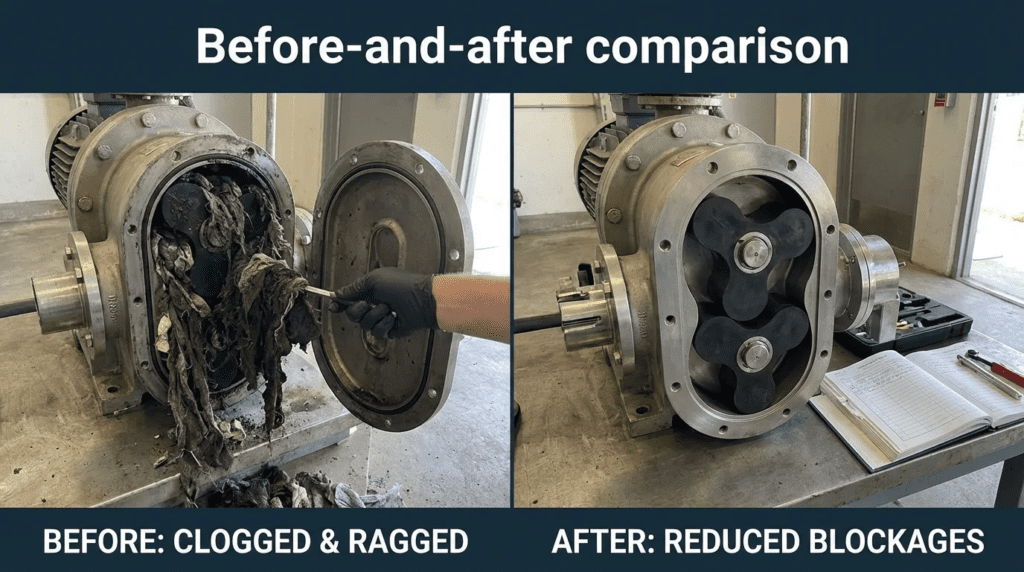
What is the difference between rubber and metal rotors regarding clogging?
Rubber rotors rely on an interference fit for sealing, which creates a high-friction “nip” point where rags can be grabbed and pulled around the rotor. Metal rotors typically have a small clearance gap. While this slightly increases slip with thin fluids, the metal surface has lower friction and a cutting/shearing edge (if designed correctly), allowing it to handle fibrous material better than rubber without wrapping.
How often should rotary lobe pumps be maintained to prevent clogging?
Preventive maintenance doesn’t stop clogging (which is an operational issue), but it prevents the damage caused by it. Operators should check oil levels weekly and inspect the lobe condition monthly. However, to reduce blockages, the focus should be on the control strategy. The “maintenance” of the anti-ragging setpoints (adjusting the amp trip level as the pump wears) is crucial. As the pump wears, its baseline amps decrease; if the trip point isn’t lowered, the pump may not detect a rag ball until it is too late.
Why is pump reversal logic important for rotary lobe pumps?
Unlike centrifugal pumps, rotary lobe pumps are bidirectional with symmetrical performance. When a blockage is detected via torque spike, reversing the flow direction pushes the blockage back out of the pump inlet (suction side), unraveling the “rope” of rags. This self-cleaning capability is a primary advantage of rotary lobe technology over progressing cavity pumps, which cannot be effectively cleared by reversing.
Conclusion
Key Takeaways for Engineers
- Don’t Oversize: Selecting a pump that runs too slowly (<100 RPM) promotes rag accumulation. Maintain adequate velocity.
- Control is Critical: A VFD with “Anti-Ragging” (auto-reverse) logic is mandatory for sludge applications.
- Material Matters: Specify hardened metal or helical rotors for high-rag environments; avoid soft rubber if possible.
- Protect the Inlet: Ensure straight suction piping and consider upstream grinding for primary sludge.
- Plan for Maintenance: Specify MIP (Maintenance In Place) designs to minimize downtime when manual de-ragging is eventually required.
Reducing blockages in rotary lobe applications is not achieved by a single “magic bullet” feature but by the convergence of correct hydraulic sizing, appropriate material selection, and intelligent control strategies. The challenge of Rotary Lobe Clogging and Ragging: How to Reduce Blockages requires the engineer to view the pump not as an isolated component, but as part of a solids-handling system that interacts with the specific rheology of the waste stream.
By shifting specifications toward helical geometries, mandating robust auto-reverse algorithms, and ensuring proper suction conditions, municipal and industrial facilities can leverage the efficiency and compactness of rotary lobe pumps without becoming slaves to daily maintenance. The goal is a system that recognizes obstructions and clears them autonomously, reserving operator intervention for true preventative maintenance rather than emergency reactive repairs.