
Preventive Maintenance Plan for Progressive Cavity (Intervals Spares Work Orders)
Introduction
In municipal wastewater treatment and industrial slurry handling, few pieces of equipment are as universally relied upon—and as frequently misunderstood—as the progressive cavity (PC) pump. While centrifugal pumps dominate clear water applications, the PC pump is the workhorse for viscous, abrasive, and shear-sensitive fluids. However, these positive displacement machines operate on a friction principle that guarantees wear. Without a robust strategy, the interference fit between the elastomeric stator and the metallic rotor becomes a ticking clock of efficiency loss. A reactive approach to these pumps results in catastrophic dry-run failures, ruptured stators, and unplanned downtime that can halt sludge dewatering or polymer injection processes entirely.
Maintenance planning for this equipment class sits downstream of every design decision made during selection. Within the broader progressive cavity pumps category, the maintenance and troubleshooting discipline is where the consequences of speed selection, elastomer choice, stage count, and drive configuration are finally paid for — in stator replacements, in confined-space labor hours, and in unplanned process interruptions. A maintenance plan cannot correct a bad specification, but a well-constructed one will reveal the specification error within the first year rather than the fifth.
The difference between a PC pump that runs reliably for five years and one that fails every six months is rarely the brand of the pump; it is the quality of the Preventive Maintenance Plan for Progressive Cavity (Intervals Spares Work Orders). Engineers often specify the duty point correctly but fail to specify the maintenance infrastructure required to sustain that duty point. In wastewater plants, where sludge characteristics change seasonally, and in industrial plants where production uptime is monetized by the minute, the maintenance strategy is as critical as the hydraulic curve.
This article provides a detailed technical framework for engineers and plant managers to design an effective lifecycle management system. It moves beyond generic “check oil” instructions to discuss the engineering logic behind wear intervals, the statistical basis for spare parts inventory, and the specific metrics required in work orders to predict failure before it occurs.
Maintenance & Troubleshooting: Subcategory Overview
A complete preventive maintenance program for progressive cavity equipment addresses three wear systems that fail on different schedules and for different reasons: the rotor-stator interference fit, the drive train and universal joints, and the shaft sealing arrangement. The first two are covered in depth throughout this article. The third — sealing — is the failure mode most likely to pull a pump out of service before its stator is worn out, and it warrants its own detailed treatment.
Seal Failures: Root Causes and Prevention
Shaft sealing on a PC pump is a harder problem than it appears, because the shaft is subject to axial thrust from the discharge pressure, radial load from the eccentric rotor motion transmitted through the connecting rod, and continuous exposure to abrasive solids that have settled in the seal chamber. Understanding the specific mechanisms behind progressive cavity seal failures — packing overtightening, flush water loss, abrasive scoring of the shaft sleeve, chemical attack on the elastomer, and thermal damage from dry running — is essential to setting realistic intervals for the rest of the plan.
The interaction with the wider maintenance program is direct. A packed stuffing box that is overtightened to stop a drip will score the shaft sleeve, and the resulting groove becomes a leak path no amount of repacking will close; the correct standard is a controlled leakage of roughly three to five drops per minute, not zero. A mechanical seal starved of flush water in a high-solids sludge application will fail in weeks rather than years, so seal flush pressure and flow should appear as measured values on the work order rather than as a checkbox. And because seal chamber temperature rises immediately during a dry-run event, seal condition is frequently the first physical evidence that run-dry protection has failed to act — which is why seal inspection findings should feed back into the review of protective instrumentation rather than being logged as an isolated repair.
For inventory planning, seal components behave differently from stators. Seal kits are inexpensive relative to rotating assemblies, have short lead times, and are consumed on a predictable cycle, which makes them the one category where generous on-shelf stocking is economically obvious across every service class.
Defining the Strategy: How to Select and Specify for Maintainability
A successful maintenance plan begins during the specification and selection phase. If a pump is specified without regard for its future maintenance requirements, even the most rigorous Preventive Maintenance Plan for Progressive Cavity (Intervals Spares Work Orders) will struggle to deliver reliability. The following criteria outline how to select equipment and define parameters that align with a proactive maintenance philosophy.
Duty Conditions & Operating Envelope
The rate of wear in a PC pump is directly proportional to the rotational speed, the abrasiveness of the media, and the operating pressure. When establishing a maintenance plan, engineers must first categorize the application severity.
- Rotational Speed (RPM): High RPM increases the sliding velocity between the rotor and stator, accelerating abrasion. A pump selected to run at 300 RPM will have a significantly different maintenance interval than one running at 100 RPM. A robust plan assumes a linear relationship: doubling the speed roughly quarters the stator life in abrasive applications.
- Pressure per Stage: PC pumps are staged to handle pressure (typically 75-90 psi per stage). Operating a 1-stage pump at 90 psi creates higher internal shear and back-slippage than operating a 2-stage pump at the same pressure. Maintenance intervals must be tightened as the pressure-per-stage ratio increases.
- Solids Content: The percentage of solids dictates the torque requirement and the potential for abrasive wear. Engineers must account for seasonal variations (e.g., higher grit loads during storm events) which necessitate more frequent inspection intervals.
Materials & Compatibility
The interaction between the rotor and stator materials is the core of PC pump performance. A mismatch here leads to rapid chemical attack or thermal failure (hysteresis), rendering standard preventive maintenance intervals useless.
- Elastomer Selection: Common materials include Buna-N (Nitrile) for general sludge, EPDM for dilute acids, and Fluoroelastomers (Viton) for high temperatures or harsh chemicals. If the fluid contains hydrocarbons, a switch from Buna-N to a specialized elastomer may extend the PM interval from months to years.
- Rotor Coatings: Standard tool steel rotors are often chrome-plated. In highly abrasive environments (like grit slurry), chrome plating may peel, slicing the stator. Specifying hardened tool steel or specialized ceramic coatings can drastically extend the “Intervals” component of the maintenance plan.
- Temperature Limits: Elastomers expand with heat. If the process temperature fluctuates, the stator may swell, increasing the compression fit and starting torque. This requires a Variable Frequency Drive (VFD) with torque monitoring capabilities to prevent burnout.
Hydraulics & Process Performance
Unlike centrifugal pumps, PC pumps provide a fixed volume per revolution. This characteristic allows for a predictive maintenance metric: volumetric efficiency.
- Slip Calculation: As the stator wears, fluid slips back from high pressure to low pressure cavities. The PM plan should include periodic “bucket tests” or flow meter verifications. Comparing current flow/RPM to the factory curve provides a quantifiable percentage of wear.
- NPSH Available (NPSHa): PC pumps have excellent suction lift capabilities, but high viscosity fluids drastically increase friction losses in suction piping. Starving the pump leads to cavitation, which tears chunks out of the stator rubber. The maintenance plan must include checking suction gauges against calculated NPSHa.
Installation Environment & Constructability
A maintenance plan is only as good as the physical access to the equipment. Engineers often overlook the “rotor removal space” requirement.
- Stator Removal Space: The stator usually slides off the end of the rotor. The installation must provide clear space equal to the length of the stator plus 12 inches. If this space requires breaking through a wall or moving other piping, maintenance will be deferred, leading to failure.
- Wobble Stator vs. Pin Joint: For smaller dosing pumps, wobble stator designs eliminate universal joints, simplifying the spares inventory. For large sludge pumps, robust pin or gear joints are necessary but require complex rebuilding procedures.
Reliability, Redundancy & Failure Modes
Understanding how PC pumps fail is critical to writing the work orders.
- Run-Dry Failure: This is the most common and expensive failure mode. The stator is lubricated by the fluid. Seconds of dry running can burn the elastomer. Reliability specifications must include run-dry protection (thermal sensors in the stator or current monitoring).
- Over-Pressure: A closed discharge valve will cause a PC pump to build pressure until a pipe bursts or the pump shaft shears. Pressure switches or rupture disks are mandatory safety devices that must be tested annually.
Controls & Automation Interfaces
Modern Preventive Maintenance Plan for Progressive Cavity (Intervals Spares Work Orders) strategies rely heavily on data.
- VFD Integration: VFDs should be programmed to monitor torque. A sudden drop in torque may indicate a run-dry condition or a broken drive train. A gradual increase may indicate stator swelling or line blockage.
- Leak Detection: Many PC pumps feature packed stuffing boxes or mechanical seals. Leak detection sensors in the seal housing can trigger a maintenance alarm before a catastrophic spill occurs.
Maintainability, Safety & Access
The physical act of maintenance must be safe and ergonomic.
- Block-and-Bleed Valves: To change a stator, the pump must be isolated. Suction and discharge isolation valves are non-negotiable.
- Lifting Lugs: Large rotors and stators are heavy and awkward. Dedicated lifting points or monorails above the pump station reduce the risk of injury and speed up the repair work order.
Lifecycle Cost Drivers
Engineers must analyze the Total Cost of Ownership (TCO). While PC pumps are efficient, their consumable costs (stators/rotors) are high.
- Energy vs. Parts: A PC pump maintains high efficiency across its curve, saving energy compared to centrifugals in viscous applications. However, the cost of a stator change-out (parts + labor) every 1-2 years must be factored into the OPEX budget.
- Spares Carrying Cost: Stocking large rotors and stators ties up capital. A “Just-in-Time” strategy is risky for critical path equipment. The maintenance plan must balance inventory costs against the risk of downtime.
Comparison Tables: Developing the Framework
The following tables provide a structured approach to categorizing failure modes and determining the appropriate maintenance strategy. Table 1 outlines the specific failure mechanisms and the corresponding prevention tactics. Table 2 offers an Application Fit Matrix to help engineers determine the criticality of the pump and the requisite depth of the maintenance plan.
Table 1: Failure Modes & Preventive Maintenance Responses
| Failure Mode | Root Cause | Early Warning Signs | Preventive Maintenance Action (Work Order Task) |
|---|---|---|---|
| Stator Burnout / Meltdown | Run-dry condition; excessive friction heat. | Burnt rubber smell; rapid rise in stator temperature; black rubber fragments in discharge. | Test dry-run protection sensors (quarterly); Inspect suction conditions/levels; Verify fluid presence before start. |
| Abrasive Wear | High solids content; high RPM; excessive pressure per stage. | Gradual loss of flow capacity; reduced discharge pressure; increased slippage. | Perform volumetric efficiency check (compare flow vs. RPM); Sample discharge for grit analysis; Reduce pump speed if possible. |
| Universal Joint Failure | Seal boot rupture leading to lubricant loss and grit intrusion. | Knocking or clicking noise; excessive vibration; “clunk” on startup. | Visual inspection of joint boots/bands (monthly); Grease analysis if oil-filled; Check drive train backlash. |
| Stator Delamination | Chemical incompatibility; manufacturing defect; vacuum conditions pulling rubber from tube. | Sudden drop in performance; rubber chunks in line; high torque spikes. | Verify chemical compatibility of elastomer; Check suction gauge for excessive vacuum; Monitor VFD torque trends. |
| Drive Shaft/Rod Breakage | Over-pressure (dead-heading); fatigue from misalignment; solid object ingestion. | Catastrophic stop; motor spinning but no flow; loud snap. | Test discharge pressure switches (annually); Inspect coupling alignment; Ensure rock traps/grinders upstream are functional. |
| Shaft Seal Failure | Packing overtightened; flush water loss; abrasive scoring of shaft sleeve; elastomer chemical attack. | Leakage rate outside the 3-5 drops/min band; product on the baseplate; seal chamber running hot. | Measure and record leakage rate (daily); Verify seal flush pressure and flow (weekly); Inspect shaft sleeve for scoring at every rebuild. |
Table 2: Maintenance Strategy & Spares Matrix
| Service Class | Typical Application | PM Interval Intensity | Spares Strategy (On-Shelf) | Work Order Complexity |
|---|---|---|---|---|
| Critical Continuous | Primary Sludge Feed to Incinerator/Centrifuge | Daily visual; Weekly performance check; Monthly vibration. | 100% Redundancy: Full spare pump on shelf or installed. Spares: 1 Rotor, 2 Stators, 2 Seal Kits, 1 Joint Kit per pump. | High: Includes predictive vibration analysis, oil sampling, and efficiency trending. |
| Critical Intermittent | WAS Transfer; Truck Loading | Weekly visual; Monthly performance check. | Rotatable Spares: 1 Spare Stator per 2 pumps. 1 Rotor per 4 pumps. Universal Joint kits in stock. | Medium: Focus on seal inspection and re-greasing. Amperage checks. |
| Non-Critical / Batch | Polymer Dosing; Sump Evacuation | Monthly visual; Quarterly performance check. | Consumables Only: Mechanical seals and O-rings. Rotors/Stators ordered on lead time or shared across fleet. | Low: Visual inspection for leaks and noise. Check oil levels. |
Selection & Specification Framework for the Maintenance Plan
The tables classify the equipment; the framework below converts that classification into a written program with defensible intervals, a sized inventory, and work order templates that produce usable data. Work the steps in order — criticality, then wear rate, then instrumentation, then inventory, then supplier support — because each step constrains the next.
Step 1 — Assign a Criticality Class to Every Pump Position
Rate each installation on process consequence (does a failure stop treatment, or fill a sump?), redundancy (is there an installed standby?), and time-to-restore (how long to obtain and fit a replacement?). Multiply rather than average: a pump with severe process consequence and no redundancy belongs in the highest class even if parts are readily available, because availability does not shorten the confined-space labor required to swap it. Most plants find that fewer than a fifth of their PC pump population belongs in the critical continuous class, which is what makes generous spares stocking for that minority affordable.
Step 2 — Establish the Wear Rate Before Setting Intervals
Do not import intervals from a manufacturer’s generic table. Measure flow at a fixed reference speed quarterly for the first year and plot the decline. That slope is the site-specific wear rate, and it converts directly into a predicted replacement date once a discard threshold is chosen. Reading the pump’s behavior against its published performance data is a skill in itself; operators trained in progressive cavity pump curve reading can distinguish a genuine wear trend from a system-head change caused by a partially blocked discharge line, which prevents the plant from replacing a healthy stator because downstream piping fouled.
Step 3 — Specify the Instrumentation That Makes the Plan Enforceable
A preventive plan built on visual inspection alone degrades to a reactive plan within two years, because visual inspection cannot see stator wear. The minimum instrumentation set is a discharge pressure transmitter, a flow measurement at or near the pump, motor current or torque feedback from the drive, and run-dry protection. Drive configuration deserves particular attention: improper VFD parameter setting is a recurring source of thermal damage, and the guidance on progressive cavity VFD setup covers the minimum speed limits, acceleration ramps, and torque limit settings that keep the drive from cooking a stator during a blocked-line event. Every instrument specified here should map to a named field on the work order template; instruments that nobody reads produce no reliability benefit.
Step 4 — Size the Inventory Against Lead Time and Consequence
Inventory sizing is a function of three numbers: expected consumption per year, supplier lead time, and the cost of a stockout. For a critical continuous pump consuming two stators per year with a twelve-week lead time, holding fewer than two on the shelf guarantees an eventual stockout during a failure. For a non-critical batch pump consuming one stator every four years, holding any is difficult to justify unless the item is shared across a standardized fleet. Standardization is the strongest lever available: a plant that has consolidated on two frame sizes across twelve pumps carries a fraction of the inventory value of a plant with nine different models.
Step 5 — Confirm Supplier Support and Parts Availability
Parts availability is a maintenance planning input, not a procurement afterthought. Before finalizing the plan, document current lead times for stators, rotors, connecting rods, joint kits, and seal kits for each installed model, and identify which items are proprietary versus available from aftermarket suppliers. Reviewing the support footprint of the major OEMs for progressive cavity pumps — regional service centers, rebuild capability, published parts lead times, and interchange availability — often reveals that two nominally equivalent pumps carry very different maintenance risk profiles. Where an installed model has weak regional support, the correct response is either to increase on-shelf stocking or to plan standardization onto a better-supported line at the next replacement cycle.
Worked Example — Setting a Stator Replacement Interval and Inventory Level
A plant operates three PC pumps feeding a belt filter press. Baseline flow at the 100 RPM reference point was 62 GPM at commissioning. Quarterly measurements over the first year returned 61, 58, 55, and 52 GPM.
- Observed decline: 62 − 52 = 10 GPM over 12 months = 0.83 GPM per month
- Discard threshold at 18% slip: 62 × 0.18 = 11.2 GPM of allowable loss
- Predicted service life: 11.2 ÷ 0.83 = 13.5 months
- Annual consumption, three pumps: 3 × (12 ÷ 13.5) = 2.7 stators per year
- Supplier lead time: 10 weeks = 0.19 years → lead-time demand = 2.7 × 0.19 = 0.5 stators
The plan therefore schedules stator replacement at 12 months — slightly ahead of the 13.5-month prediction to keep the work inside a planned outage — and sets a minimum stock of two stators with a reorder point of one. Two rather than one is justified by the failure correlation: these three pumps see identical service, so when one reaches its discard limit the others are close behind, and a single-unit stock would be consumed on the first work order of the cycle. The same arithmetic applied to seal kits, which are consumed roughly twice as often but cost a fraction as much and arrive in two weeks, yields a stock of four with a reorder point of two.
Engineer & Operator Field Notes
Implementing a Preventive Maintenance Plan for Progressive Cavity (Intervals Spares Work Orders) requires bridging the gap between the O&M manual and the reality of the plant floor. The following notes are derived from field experience and address common execution challenges.
Commissioning & Acceptance Testing
The baseline for all future maintenance is established during commissioning. Without accurate baseline data, it is impossible to determine if vibration is increasing or if efficiency is dropping.
- Break-away Torque: Record the torque required to start the pump with water (or process fluid). A tight stator will have high starting torque. As it wears, this value drops. If it rises later in life, it indicates swelling.
- Temperature Baseline: Measure the stator temperature at the inlet, middle, and discharge after 1 hour of running. The discharge end is typically warmer due to friction and pressure, but a delta greater than 20°F (approx 11°C) suggests excessive friction or insufficient lubrication.
- Flow vs. Speed Curve: Do not rely on the generic factory curve. Generate a site-specific curve (e.g., Flow at 20Hz, 40Hz, 60Hz) against the actual system head. This is your “Day 1” benchmark.
- Seal Baseline: Record the packing leakage rate after the initial run-in and bedding period, or the seal flush pressure and flow rate for mechanically sealed units. Photograph the shaft sleeve condition before final assembly so future scoring can be assessed against a known starting point.
- Protective Device Proof Test: Functionally test every protective device before handover — run-dry sensor, high discharge pressure switch, and drive torque limit — by simulating the condition rather than by reviewing the wiring drawing. Record the actual trip setpoint achieved, not the intended one.
Common Specification Mistakes
Engineers frequently inadvertently sabotage the maintenance plan through poor specification practices.
- Oversizing the Pump: Engineers often apply large safety factors, resulting in a pump that must run at very low speeds (e.g., <10 Hz) to meet the flow requirement. At very low speeds, the “slip” becomes a larger percentage of the total flow, making the pump appear inefficient and causing flow pulsation issues.
- Ignoring “Rotatable” Spares: Specifying a “spare rotating assembly” is often better than individual parts. It allows maintenance to swap the entire rotor/stator/joint assembly in one go (a 4-hour job) and rebuild the worn assembly on the bench (a 2-day job), minimizing downtime.
- Vague Lubrication Specs: Gear joints and pin joints often require specific semi-fluid greases or oils. Specifying “general purpose grease” can lead to joint failure. Ensure the work order lists the specific OEM-approved lubricant.
O&M Burden & Strategy
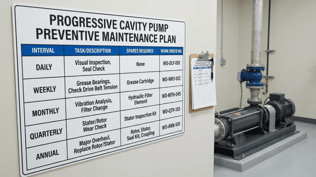
The core of the plan is the scheduling of interventions. A typical interval schedule should look like this:
- Daily: Check for seal leakage (max 3-5 drops/min for packing; zero for mechanical). Check discharge pressure. Listen for “knocking” (joints) or “squealing” (dry run).
- Weekly: Check bearing temperature. Inspect drive belts or coupling guards. Verify VFD torque readings against the baseline.
- Quarterly: Lubricate bearings (if greaseable). Check gear reducer oil level. Perform a “bucket test” or flow meter verification to calculate slip. Inspect foundation bolts.
- Annually: Change gear reducer oil. Inspect universal joint boots for cracks. Perform a complete amperage draw analysis across the speed range. Test all safety shutdowns (pressure switches, run-dry protection).
Troubleshooting Guide
When the pump deviates from the plan, rapid diagnosis is key.
- Symptom: No Flow. Check: Is the pump rotating? Is the suction valve open? Is the stator completely worn (check fit)? Is the suction line collapsed?
- Symptom: Excessive Noise. “Clunking” usually indicates worn universal joints. “Popping” indicates the rotor is jumping over the stator lobes due to extreme wear or over-pressure. “Screeching” indicates dry running or bearing failure.
- Symptom: Short Stator Life. Check: Is the speed too high? Is the media more abrasive than specified? Is the pressure higher than the stage rating? Is the elastomer chemically attacked (swollen/soft/hard)?
Design Details & Engineering Calculations
To move from a qualitative to a quantitative Preventive Maintenance Plan for Progressive Cavity (Intervals Spares Work Orders), engineers must utilize specific calculations to predict wear and justify replacement intervals.
Sizing Logic & Methodology
The “sizing” of the maintenance plan is based on the Wear Index. While not a formal ASTM standard, it is a practical engineering concept used to determine inspection frequency.
Wear Rate ∝ (Speed)2 × (Pressure) × (Abrasiveness)
Because wear increases with the square of the speed, a pump running at 50% of its rated speed will theoretically last four times longer than one running at 100%. Therefore, the PM plan for a pump running near its maximum RPM must have inspection intervals four times more frequent.
Calculating Slip for Stator Replacement
The most objective way to trigger a stator replacement work order is by calculating the Slip Percentage.
Step 1: Determine Theoretical Displacement. Obtain the specific displacement per revolution (gallons/rev) from the manufacturer.
Step 2: Calculate Theoretical Flow. Theoretical Flow = RPM × Displacement/Rev
Step 3: Measure Actual Flow. Use a flow meter or drop test.
Step 4: Calculate Slip. Slip = Theoretical Flow – Actual Flow
Step 5: Determine Threshold. A new pump typically has <5% slip. When slip reaches 15-20% (depending on the application criticality), it becomes energy-inefficient and prone to “blow-by” failure, triggering a replacement work order.
Specification Checklist
When creating the Work Order templates for the CMMS (Computerized Maintenance Management System), ensure the following data points are required fields:
- Rotor Diameter Measurement: Measure the rotor diameter at the minor and major axes. Compare to OEM discard specs.
- Stator Condition: Visual inspection for pitting, gouging, or chemical attack.
- Joint Play: Measure the backlash in the universal joints. Any perceptible lag between the drive shaft and the rotor indicates joint wear.
- Seal Leakage Rate: Quantify leakage (e.g., “drops per minute”) rather than qualitative terms like “leaking a little.”
- Reference-Point Flow: Flow in GPM measured at a fixed reference speed, recorded alongside discharge pressure. This is the single field that makes wear trending possible; without a fixed reference speed the readings are not comparable.
- Motor Current or Torque: Amperage at the reference speed, compared against the commissioning baseline, to separate hydraulic wear from mechanical binding.
- Parts Consumed: Part numbers and quantities issued against the work order, so consumption data feeds inventory reorder points automatically rather than through an annual manual review.
Standards & Compliance
No single standard governs preventive maintenance for progressive cavity equipment; the program assembles requirements from several sources. Mechanical design, testing, and seal arrangement practice draw on API 676 for rotary positive displacement pumps and ISO 14847 for technical requirements. Safety procedures during maintenance are governed by OSHA 29 CFR 1910.147 for lockout/tagout, 29 CFR 1910.146 where the installation is in a permit-required confined space, and 29 CFR 1910.212 for machine guarding of exposed drive components. Where reliability program structure is being formalized, ISO 55000 for asset management and ISO 14224 for equipment failure data collection provide the frameworks most utilities use to make maintenance records auditable and comparable across a fleet.
Ensure the maintenance plan adheres to relevant standards:
- API 676: Standard for Positive Displacement Pumps – Rotary. While primarily oil & gas, it offers excellent guidelines for seal plans and baseplate stiffness which affect reliability.
- ISO 14847: Rotary positive displacement pumps – Technical requirements.
- OSHA 1910.147: The Lockout/Tagout (LOTO) procedure is critical for PC pumps. Because the rotor can store potential energy (compressed rubber) or backspin due to head pressure, specific procedures for relieving pressure before opening the pump are mandatory.
Frequently Asked Questions
What is a Preventive Maintenance Plan for Progressive Cavity (Intervals Spares Work Orders) specifically?
This is a structured documentation system that defines when to maintain a PC pump (Intervals), what parts to have on hand to minimize downtime (Spares), and how to perform the tasks (Work Orders). It shifts maintenance from reactive “break-fix” to proactive reliability management, focusing on stator wear monitoring and joint lubrication.
How often should I replace the stator on a PC pump?
There is no single answer, but typical intervals range from 6 months for severe grit applications to 5+ years for clean polymer dosing. The replacement should be triggered by condition monitoring (e.g., when flow drops by 15% at a constant speed) rather than a fixed calendar date. However, an annual inspection is recommended to establish the wear rate.
Why do progressive cavity pumps fail immediately after dry running?
PC pumps rely on the pumped fluid to lubricate the interference fit between the rubber stator and metal rotor. Without fluid, the friction generates immense heat almost instantly, causing the rubber to burn, glaze, and seize against the rotor. This can destroy a stator in minutes. Dry-run protection is essential.
What are the critical spares for a PC pump maintenance plan?
At a minimum, the inventory should include one stator and one set of universal joint seals/boots. For critical applications, a “rotating assembly” (rotor, stator, connecting rod, and joints pre-assembled) is recommended to allow for rapid swap-outs. Mechanical seals should also be stocked if used.
How do I calculate the wear rate for my maintenance intervals?
Establish a baseline flow rate at a specific RPM (e.g., 50 GPM at 100 RPM). Measure the flow every quarter at that same RPM. Plot the decline in flow over time. If you lose 1 GPM per month, and your discard limit is a 10 GPM loss, you can predict a 10-month service life and schedule the work order accordingly.
Can I just tighten the stator to extend its life?
Most standard PC pumps have non-adjustable stators. Once the interference fit is worn, the stator must be replaced. However, some manufacturers offer “adjustable” stators with a split housing that can be tightened to compress the rubber. While this extends life, it is a temporary fix and can alter the internal geometry, potentially causing uneven wear.
What is the difference between a pin joint and a gear joint in maintenance terms?
Pin joints are simpler and cheaper but wear out faster and are prone to “ovaling” in the rod. They are field-replaceable but require frequent inspection. Gear joints are sealed, oil-filled, and handle higher torque and misalignment for longer periods (years). However, if a gear joint fails, it usually requires a factory rebuild or a complete new assembly.
How many spare stators should a plant actually hold on the shelf?
Calculate lead-time demand rather than guessing. Multiply annual consumption for the pump family by the supplier’s lead time expressed in years, then add a buffer sized to the consequence of a stockout. A family of three identical critical pumps consuming 2.7 stators per year with a ten-week lead time generates a lead-time demand of about half a unit, but a minimum stock of two is appropriate because identical pumps in identical service reach their discard limit at nearly the same time. For non-critical batch service with a single pump, holding no stator and accepting the lead time is often defensible. Seal kits are the exception across every class — low cost, short lead time, and high consumption make generous stocking obviously worthwhile.
Conclusion
Key Takeaways
- Preventive Maintenance Plan for Progressive Cavity (Intervals Spares Work Orders) is not just a document; it is a lifecycle strategy that impacts CAPEX and OPEX.
- Dry Running is Fatal: 90% of premature PC pump failures are due to run-dry conditions. Sensors are cheaper than stators.
- Speed Kills: Wear increases with the square of the speed. Oversizing the pump to run slower pays dividends in reduced maintenance.
- Monitor Efficiency, Not Just Vibration: The earliest sign of PC pump wear is a drop in volumetric efficiency (Slip), not vibration.
- Rotatable Spares: For critical processes, stock complete rotating assemblies, not just loose parts, to minimize Mean Time To Repair (MTTR).
- Standardize Work Orders: Ensure maintenance tasks include specific measurements (e.g., “Record Flow @ 30Hz”) rather than generic “Inspect Pump” instructions.
- Measure Before You Schedule: Set intervals provisionally, measure flow quarterly at a fixed reference speed for the first year, then reset the interval against the site-specific wear slope rather than a generic table.
Developing a robust Preventive Maintenance Plan for Progressive Cavity (Intervals Spares Work Orders) requires a shift in mindset from treating the pump as a “fit and forget” asset to treating it as a dynamic system that requires constant monitoring. The interaction between the abrasive fluid, the elastomeric stator, and the metallic rotor is a complex tribological system that demands respect.
For engineers, the task is to specify pumps that are maintainable—considering access, materials, and instrumentation. For operators, the task is to execute work orders that gather actionable data, allowing the organization to predict failure before it halts production. By aligning the selection criteria with a disciplined spares strategy and data-driven intervals, utilities and industries can transform the PC pump from a maintenance headache into a reliable, efficient cornerstone of their process.