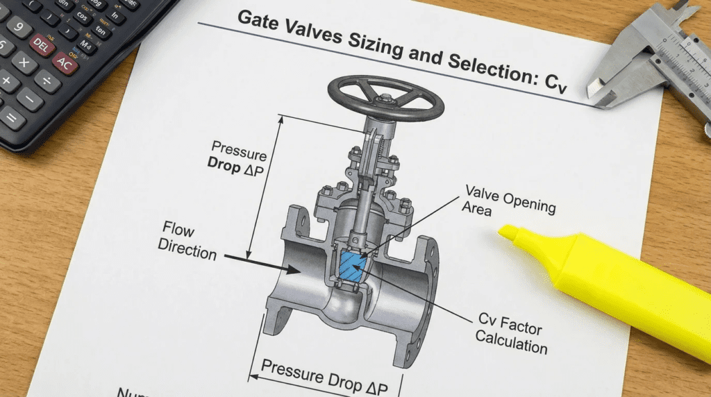
Gate Valves Sizing and Selection: Cv
INTRODUCTION
In municipal water, wastewater, and industrial fluid transport systems, gate valves are the quintessential isolation mechanism. However, a common misconception plagues piping design: the assumption that because gate valves are typically operated either fully open or fully closed, calculating their flow coefficient is unnecessary. This oversight makes Gate Valves Sizing and Selection: Cv one of the most frequently misunderstood aspects of hydraulic design. When consulting engineers merely specify a gate valve to match the nominal pipe size without evaluating its flow coefficient ($C_v$), they risk introducing undocumented friction losses, localized velocity spikes, and long-term energetic inefficiencies into the pumping system.
The flow coefficient, $C_v$, represents the volume of water (in US gallons per minute at 60°F) that will flow through a valve with a pressure drop of exactly 1 psi. While control valves rely heavily on $C_v$ curves for throttling accuracy, gate valves require rigorous $C_v$ analysis to evaluate the wide-open head loss, transient surge modeling (water hammer), and the economic viability of utilizing reduced-port valves to save capital expenditure (CAPEX).
Gate valves are ubiquitous in treatment plant galleries, distribution networks, pump station dry wells, and raw water intakes. They operate in harsh environments ranging from buried service with aggressive soils to highly corrosive industrial wastewater streams. A poor specification—such as selecting a solid wedge gate valve for wastewater slurry where a knife gate is required, or undersizing a resilient wedge gate valve to cut initial costs—inevitably leads to increased operational expenditure (OPEX) via pumping energy, premature seat failure, and catastrophic stem shearing.
This technical guide is written specifically for design engineers, utility managers, and operators. It provides a comprehensive, unbiased methodology for approaching Gate Valves Sizing and Selection: Cv. By mastering the integration of fluid dynamics with valve mechanics, engineers can optimize system performance, ensure long-term reliability, and accurately calculate the true total cost of ownership (TCO) of their isolation infrastructure.
HOW TO SELECT / SPECIFY
Duty Conditions & Operating Envelope
The foundation of gate valve specification lies in accurately defining the operating envelope. While primarily designed for on/off isolation service, the dynamic conditions during the opening and closing phases dictate the structural requirements of the valve.
- Flow Rates and Velocities: Typical maximum pipeline velocities for water and wastewater applications range from 5 to 8 feet per second (ft/s). Exceeding approximate limits of 15 ft/s across a partially open gate during transient operation can cause severe vibration, chatter, and mechanical damage to the wedge guides.
- System Pressures: Engineers must evaluate both the steady-state working pressure and the maximum transient (surge) pressure. Valves are typically specified with pressure classes such as Class 150, Class 300, or specific AWWA ratings (e.g., 200 psi or 250 psi water working pressure). The differential pressure ($Delta P$) across the valve when closed determines the required actuator torque or manual rim pull force.
- Operating Modes: Gate valves should not be used for continuous throttling. If a system requires flow modulation, butterfly, plug, or globe valves are appropriate. Gate valves are strictly for continuous fully open or intermittent isolation duty.
- Media Characteristics: The presence of suspended solids, grit, or fibrous rags dictates the wedge type. Raw wastewater necessitates designs that eliminate bottom cavities (where debris can accumulate) or shearing actions, such as knife gate valves.
Materials & Compatibility
Material selection directly impacts the mean time between failures (MTBF). Engineers must match metallurgical and elastomeric properties to the fluid chemistry.
- Body and Bonnet: Ductile iron (ASTM A536) is the industry standard for municipal water/wastewater due to its high tensile strength and impact resistance compared to cast iron. For highly corrosive industrial effluent, stainless steel (316/316L) or duplex stainless steels may be required.
- Wedge/Disc: In AWWA C509/C515 resilient-seated gate valves, the ductile iron wedge is fully encapsulated in an elastomer. Ethylene Propylene Diene Monomer (EPDM) is typical for chloramine-treated potable water and general wastewater. Nitrile (NBR/Buna-N) must be specified if the fluid contains hydrocarbons, fats, oils, or greases (FOG).
- Stems: The stem transfers rotational torque to linear motion. Common materials include various grades of stainless steel (Type 304, 316, 420) and cast bronzes. Type 420 stainless steel is often favored for its superior yield strength and resistance to galling, which is critical for preventing snapped stems during high-torque operation.
- Coatings: For municipal service, internal and external surfaces should be coated with Fusion Bonded Epoxy (FBE) in accordance with AWWA C550, typically applied to a nominal thickness of 8-12 mils to prevent tuberculation and corrosion.
Hydraulics & Process Performance: The Role of Gate Valves Sizing and Selection: Cv
Hydraulic performance is where the concept of Gate Valves Sizing and Selection: Cv becomes critical. Even fully open, a valve introduces friction into the piping system.
- Full-Port vs. Reduced-Port: A true full-port gate valve has an internal diameter equal to or slightly larger than the connecting pipe, yielding an exceptionally high $C_v$ and near-zero head loss. Reduced-port valves (often used to save money on larger diameters) intentionally constrict flow, significantly lowering the $C_v$ and increasing pressure drop.
- Calculating Head Loss: Using the manufacturer’s published $C_v$, the pressure drop ($Delta P$) in psi can be calculated as:
ΔP = SG * (Q / Cv)², where $Q$ is flow in GPM and $SG$ is specific gravity. In large transmission mains, even a 0.5 psi drop across a reduced-port valve equates to roughly 1.15 feet of additional head the pumps must overcome continuously. - Transient Analysis Input: Hydraulic modeling software (e.g., InfoWater, Bentley WaterGEMS) requires accurate $C_v$ curves representing the valve from 0% to 100% open. Gate valves have non-linear flow characteristics; the majority of flow reduction occurs in the last 20% of closure. Knowing the $C_v$ decay curve is vital for calculating water hammer potential and designing surge suppression equipment.
Installation Environment & Constructability
The physical constraints of the installation site dictate the mechanical configuration of the valve.
- Stem Orientation: Non-Rising Stem (NRS) valves are typically used for buried service and applications with limited vertical clearance. Outside Screw and Yoke (OS&Y) valves are preferred in fire protection systems and exposed plant piping because the exposed stem provides immediate visual indication of the valve’s position (open/closed).
- Actuator Orientation: Gate valves are ideally installed with stems vertical. Installing them horizontally (stem on the side) in large diameters can cause the wedge to drag on the bottom guide track, accelerating wear. If horizontal installation is mandatory, manufacturers must supply rollers, tracks, or scrapers.
- Buried Service: Requires appropriate extension stems, 2-inch AWWA operating nuts, and valve boxes. Soil corrosivity testing should dictate whether supplemental polyethylene encasement (polywrap) is required per AWWA C105.
Reliability, Redundancy & Failure Modes
Gate valves are often expected to sit idle for years, yet operate flawlessly during an emergency. Understanding failure modes informs specification.
- Failure to Isolate: In older metal-seated solid wedge gates (AWWA C500), debris accumulating in the bottom pocket prevents the wedge from seating, causing “let-by” or leakage. Resilient seated valves eliminate this pocket, but the elastomer can be permanently deformed by severe over-torquing.
- Stem Failure: Excessive torque applied by operators trying to force a jammed valve closed will shear the stem or strip the operating nut. Stem yield strength must exceed the maximum expected manual rim pull force (typically evaluated at an approximate 200 lbs of pull on a handwheel).
- Packing Leaks: O-ring stem seals (typically two or three O-rings) have largely replaced traditional adjustable packing glands in municipal water valves, reducing maintenance. Specifications should require that O-rings be replaceable under pressure while the valve is in the fully open position (backseated).
Controls & Automation Interfaces
When automated via electric, pneumatic, or hydraulic actuators, the valve specification must interface perfectly with the control system.
- Torque Sizing: Actuators are sized based on the maximum differential pressure ($Delta P$) across the wedge. The “break-to-open” torque is generally the highest force required. If a valve is undersized (low $C_v$), the resulting higher velocity and $Delta P$ will require a significantly larger, more expensive actuator.
- Limit and Torque Switches: Motorized actuators must rely on position limit switches for the “open” position but should utilize torque switches for the “closed” position to ensure a positive seal without crushing the resilient wedge.
- SCADA Integration: Actuators should provide discrete feedback for fully open/fully closed status, and optionally 4-20mA continuous position feedback, communicating via protocols like Modbus TCP/IP, Ethernet/IP, or Profibus depending on plant architecture.
Maintainability, Safety & Access
Valves must be accessible for safe operation and maintenance. A valve that cannot be safely reached will not be maintained.
- Ergonomics: Handwheels or chainwheels should be positioned at an operable height (typically 3 to 4 feet above the operating floor). Chainwheels must include safety secondary retention cables.
- Lockout/Tagout (LOTO): Handwheels and actuators must feature physical lockout provisions to comply with OSHA regulations, ensuring the valve cannot be inadvertently opened during downstream maintenance.
- Exercising Access: For buried valves, clear access to the valve box is required. Utility programs should mandate exercising valves (fully closing and opening) on an approximate 1-to-3-year cycle to prevent calcification and verify operability.
Lifecycle Cost Drivers
Evaluating Gate Valves Sizing and Selection: Cv intrinsically links to lifecycle cost analysis (LCCA).
- CAPEX vs. OPEX: A 24-inch reduced-port gate valve might cost 15% less upfront than a full-port 24-inch valve. However, the reduced $C_v$ increases head loss. Over a typical 20-to-40-year lifespan, the continuous excess electrical energy required by the pumps to overcome this friction will massively eclipse the initial capital savings.
- Repair and Replacement: The labor cost to excavate and replace a failed buried gate valve far exceeds the purchase price of the valve itself. Specifying higher-grade materials (e.g., 316 SS stems, extra-heavy epoxy coatings) minimizes replacement frequency.
COMPARISON TABLES
The following tables provide an engineering comparison of gate valve technologies and an application fit matrix. Use these matrices to align operational constraints with the correct valve architecture and to verify initial sizing assumptions.
| Technology / Valve Type | Primary Features & Mechanism | Best-Fit Applications | Limitations & Considerations | Typical Maintenance |
|---|---|---|---|---|
| Resilient Wedge (AWWA C509/C515) | Elastomer-encapsulated ductile iron wedge. Flat-bottom body geometry. Zero-leakage bi-directional seating. | Potable water, distribution networks, pump station isolation, primary/secondary treated wastewater effluent. | Not suitable for throttling. Elastomers degrade with certain chemicals or extreme temperatures. Max temp approx. 150°F. | Periodic exercising. O-ring replacement (infrequent). Visual inspection of epoxy coating if accessible. |
| Solid Wedge / Metal-Seated (AWWA C500) | Cast or ductile iron wedge with bronze/stainless seat rings. Relies on metal-to-metal contact. Pocketed bottom. | High-temperature fluids, older existing distribution systems, applications where elastomers are incompatible. | Debris collects in bottom pocket preventing complete closure. Prone to minor “let-by” leakage. Higher operating torque. | Flushing of bottom track. Seat grinding/lapping (rare/difficult in field). Packing adjustment. |
| Knife Gate (AWWA C520) | Thin, beveled stainless steel blade that cuts through solids. Elastomer or metal seating. Narrow face-to-face dimension. | Raw sewage, primary sludge, RAS/WAS lines, industrial slurry, grit chambers. | Typically uni-directional sealing (bi-directional available but complex). Standard models are not fully leak-proof to atmosphere at the top packing. | Packing gland tightening/replacement. Blade cleaning. Actuator lubrication. |
| Double Disc / Parallel Slide | Two separate discs forced against opposing seats by a spreading mechanism upon closure. | Large diameter transmission mains, high-pressure liquid pipelines. | Complex internal mechanics. Expensive. Can become locked if temperature transients cause body contraction around discs. | Complex internal repairs. Mechanism lubrication and tolerance verification during major overhauls. |
| Application Scenario | Typical Diameter Range | Service Fluid | Optimal Valve Choice | Critical Sizing / Cv Consideration |
|---|---|---|---|---|
| Municipal Potable Water Distribution | 4″ – 36″ | Clean Water (Chlorinated) | Resilient Wedge (EPDM) | Line-size for max $C_v$; minimal pressure drop is critical for network pressure maintenance. |
| Raw Wastewater Lift Station Dry Well | 6″ – 24″ | Raw Sewage (Rags, Grit) | Knife Gate or Resilient Wedge | Avoid reduced ports that could snag rags. Full-port $C_v$ ensures clearing of solids. |
| Wastewater Sludge (RAS/WAS) | 4″ – 12″ | Viscous Slurry (1-5% solids) | Knife Gate (Bi-directional seat) | Viscosity corrections must be applied to $C_v$ calculations to determine actual head loss in non-Newtonian sludge. |
| Pump Discharge Header (Isolation) | 8″ – 48″+ | Clean/Treated Water | Resilient Wedge or Double Disc | Must analyze $C_v$ during transient opening/closing to define pump control curves and prevent check valve slam. |
| Industrial Chemical Effluent | 2″ – 16″ | Corrosive liquids, Solvents | Stainless Solid Wedge / Knife | Ensure $C_v$ sizing accounts for the specific gravity of the industrial fluid to correctly calculate pump head. |
ENGINEER & OPERATOR FIELD NOTES
Commissioning & Acceptance Testing
Proper commissioning ensures that the theoretical benefits calculated during the Gate Valves Sizing and Selection: Cv phase translate into real-world reliability.
- Hydrostatic Testing: Prior to field installation, manufacturers should perform hydrostatic body and seat tests per AWWA standards (e.g., body tested to twice the rated working pressure, seat tested at rated pressure). Field hydro-testing of the entire pipeline must ensure valves are in the open position to avoid over-pressurizing one side of the gate beyond its rating.
- Torque Verification: For manual valves, verify the number of turns to open/close (typically roughly 3 turns per inch of diameter) and the ease of operation. High resistance during dry commissioning may indicate binding or improper alignment.
- Actuator Setup (SAT): During Site Acceptance Testing (SAT), limit switches must be meticulously calibrated. If the close limit is set incorrectly, the actuator will either fail to isolate flow or crush the wedge against the body, causing irreversible damage. Verify the manual override handwheel functions correctly while the motor is declutched.
Common Specification Mistakes
Engineers often rely on outdated boilerplate specifications, leading to several common pitfalls:
- Confusing AWWA C509 and C515: C509 specifies thick-walled ductile or cast iron. C515 specifies thinner-walled, high-strength ductile iron. Both perform equally well in most applications, but C515 valves are lighter and often more cost-effective. Specifying “AWWA C509 only” arbitrarily eliminates modern C515 designs without technical merit.
- Ignoring Bypass Requirements: For large valves (typically 16-inch and larger) under high differential pressure, operating torque can be massive. Failing to specify an integrally cast or piped bypass valve forces operators to fight immense hydraulic forces. A small bypass valve equalizes pressure, dropping the $Delta P$ effectively to zero before the main gate is opened.
- Overlooking Actuator Duty Cycles: Specifying an ON/OFF isolation actuator (duty cycle of roughly 15 minutes or 15 starts per hour) for a gate valve that, due to process instability, is commanded to open and close constantly, will burn out the actuator motor.
O&M Burden & Strategy
Gate valves are uniquely vulnerable to “neglect until failure.” An effective O&M strategy requires proactive intervention.
- Valve Exercising Program: The single most critical maintenance task is routine exercising. Every utility should mandate that critical isolation valves be fully closed and reopened annually. This clears tuberculation from the tracks, tests the integrity of the stem, and verifies the valve’s mapped location.
- Tracking Torque and Turns: Operators should log the number of turns and the applied torque (using smart valve exercising machines) during maintenance. An unexplained increase in required torque is a leading indicator of impending stem failure or severe internal fouling.
- Spare Parts: For custom or large-diameter valves, maintaining a site inventory of consumable spares is critical. This includes stem O-ring kits, cover gaskets, and for knife gates, replacement packing material (e.g., PTFE-impregnated synthetic fiber).
Troubleshooting Guide
When an operator encounters a problematic gate valve, diagnostic procedures should follow a systematic approach:
- Valve Will Not Close Completely (Let-by): For resilient wedge valves, debris may be trapped under the wedge. Fix: Open the valve slightly to allow high-velocity flow to flush the seat area, then attempt to close again. Never force it with a “cheater bar.”
- Stem Turns but Valve Does Not Operate: Indicates a sheared stem or a stripped wedge nut. Diagnosis: If the stem spins freely with zero resistance, mechanical failure has occurred. Fix: Requires system shutdown, removal of the bonnet, and replacement of the stem/nut assembly.
- Water Leaking from Stem/Packing Area: Fix: For older valves, tighten the packing gland bolts evenly. For modern resilient wedge valves, back-seat the valve (open fully to seal the stem against the bonnet) and replace the upper O-rings under pressure.
DESIGN DETAILS / CALCULATIONS
Sizing Logic & Methodology: The Math of Flow Coefficients
Mastering Gate Valves Sizing and Selection: Cv requires understanding the mathematical relationship between flow, pressure, and energy.
The fundamental equation for the flow coefficient is:
Cv = Q * √(SG / ΔP)
Where:
Cv= Valve flow coefficientQ= Flow rate in US Gallons per Minute (GPM)SG= Specific Gravity of the fluid (Water = 1.0)ΔP= Pressure drop across the valve in psi
For engineering applications, we usually know the flow rate ($Q$) and the manufacturer’s published $C_v$ for a fully open valve, and we need to solve for the pressure drop ($Delta P$) to calculate pump head requirements:
ΔP = (Q / Cv)² * SG
Worked Lifecycle Cost Example:
An engineer is sizing an isolation valve for a pump discharge moving 5,000 GPM.
Option A: 16-inch Full-Port Gate Valve ($C_v$ approx. 15,000)
Option B: 12-inch Reduced-Port Gate Valve ($C_v$ approx. 6,000)
Pressure Drop Option A: ΔP = (5000 / 15000)² = 0.11 psi (approx. 0.25 ft of head)
Pressure Drop Option B: ΔP = (5000 / 6000)² = 0.69 psi (approx. 1.6 ft of head)
While 1.35 feet of extra head seems minimal, consider a pump operating 24/7 at 75% wire-to-water efficiency, with electricity at $0.12/kWh. Over 20 years, that extra friction loss from the reduced-port valve will consume tens of thousands of dollars in wasted electrical energy. This calculation proves why evaluating Gate Valves Sizing and Selection: Cv is not just a theoretical exercise, but an economic imperative.
Specification Checklist
To ensure robust procurement, specifications should explicitly demand:
- Standard Compliance: Strict adherence to AWWA C509, C515, or C520.
- Wedge Encapsulation: Resilient wedges must be fully encapsulated in EPDM or NBR, with no exposed iron.
- Hardware: All internal and external bolting must be Type 304 or 316 Stainless Steel to prevent galvanic corrosion.
- Coating Thickness: Fusion Bonded Epoxy (FBE) to AWWA C550, holiday-free, minimum 8 mils dry film thickness (DFT).
- Testing Documentation: Certified hydrostatic and seat leakage test reports (FAT) must be submitted prior to shipment.
Standards & Compliance
Familiarity with industry standards is non-negotiable for design engineers:
- AWWA C500: Covers metal-seated gate valves (largely legacy for municipal water, but still used in specific high-temp or abrasive applications).
- AWWA C509: Covers resilient-seated gate valves with thick-wall cast or ductile iron bodies.
- AWWA C515: Covers resilient-seated gate valves with reduced-wall, high-strength ductile iron bodies.
- AWWA C520: Covers knife gate valves for water and wastewater applications.
- NSF/ANSI 61 & 372: Mandatory for potable water applications. Ensures components do not leach toxic chemicals (e.g., lead) into drinking water.
FAQ SECTION
What is Cv in gate valve sizing?
The flow coefficient ($C_v$) represents the flow rate in US GPM of 60°F water that causes a 1 psi pressure drop across a fully open valve. In Gate Valves Sizing and Selection: Cv analysis, it is used to calculate the friction head loss introduced into the piping system, which directly impacts pump sizing and energy consumption.
Can gate valves be used for throttling flow?
No. Gate valves are designed strictly for on/off isolation service. Operating a gate valve in a partially open position causes high-velocity flow across the wedge, leading to severe vibration, cavitation, premature wear of the elastomer or metal seats, and potential mechanical failure of the stem and guides.
Why is calculating Cv important if gate valves are usually line-sized?
While gate valves are often sized to match the pipe diameter, evaluating $C_v$ is crucial for three reasons: 1) To accurately define the system head curve for pump selection; 2) To perform transient analysis (water hammer modeling) using the valve’s $C_v$ decay curve during closure; and 3) To evaluate the OPEX energy penalties if a reduced-port valve is proposed by a contractor to lower capital costs.
What is the difference between AWWA C509 and C515 gate valves?
AWWA C509 permits the use of cast iron or ductile iron and requires a thicker wall geometry. AWWA C515 mandates the use of high-strength ductile iron, allowing for thinner walls. As a result, C515 valves are lighter and easier to install, while offering the same or superior pressure ratings and performance as C509 valves.
How often should municipal gate valves be exercised?
Best practices dictate that critical water distribution and wastewater isolation gate valves should be exercised (fully closed and reopened) at least once every 1 to 3 years. This preventative maintenance breaks up internal scale/tuberculation, verifies operability, and identifies failing stems before an emergency occurs.
Why do gate valve stems break?
Stem shear typically occurs due to excessive manual force applied by operators attempting to close a valve that is jammed by debris in the seat, or attempting to open a valve suffering from galvanic binding or calcification. Specifying higher yield strength stem materials (e.g., 420 SS) and implementing routine exercising programs mitigates this failure mode.
CONCLUSION
- Never use for throttling: Gate valves are on/off isolation devices; partial opening causes destructive vibration and seat wear.
- Cv matters for OPEX: Evaluating Gate Valves Sizing and Selection: Cv is critical to understanding lifecycle pumping costs; reduced-port valves save CAPEX but cost significant OPEX in head loss.
- Match elastomers to fluid: Specify EPDM for standard water/wastewater, but mandate NBR (Nitrile) if hydrocarbons or FOG are present.
- Specify bypasses for large diameters: Valves 16-inch and larger operating under high differential pressure require bypass lines to equalize pressure and reduce opening torque.
- Exercise to survive: A rigid 1-to-3-year valve exercising program is the single best defense against stem failure and calcification.
Approaching Gate Valves Sizing and Selection: Cv requires a paradigm shift away from the simplistic “line-size and forget” mentality. For municipal and industrial engineers, every component placed in a pipeline alters the system’s hydraulic efficiency. By utilizing the flow coefficient to quantify pressure drop, engineers can make empirical, data-driven decisions that balance initial capital costs against long-term energy expenditures.
The successful specification of a gate valve hinges on understanding the nuances of duty conditions, material compatibility, and actuation forces. Selecting between a resilient wedge AWWA C515 and a rugged knife gate valve depends entirely on the fluid mechanics and solids loading of the specific application. Furthermore, considering operator ergonomics and maintenance access during the design phase ensures that the equipment can be safely and consistently maintained throughout its multi-decade lifespan.
When plant directors and public works decision-makers prioritize comprehensive hydraulic analysis and adherence to strict AWWA standards over lowest-bidder commodity purchasing, they secure resilient, efficient infrastructure. By applying the principles detailed in this guide, engineering teams can confidently design pumping systems and fluid networks that perform predictably, minimize energy waste, and dramatically reduce catastrophic operational failures.