
Advanced Disinfection Technologies in Wastewater Treatment: A Complete Guide
Introduction
For decades, municipal and industrial wastewater treatment facilities relied on chlorine gas or sodium hypochlorite for final effluent disinfection. While effective at pathogen inactivation, traditional chlorination presents severe operational liabilities: the generation of toxic disinfection byproducts (DBPs) such as trihalomethanes (THMs) and haloacetic acids (HAAs), the requirement for costly dechlorination steps (typically using sodium bisulfite) to protect aquatic life, and significant site safety and regulatory burdens (e.g., OSHA Process Safety Management).
As discharge permits tighten—driven by stringent receiving-water limits, water reuse initiatives, and the need to address chlorine-resistant pathogens like Cryptosporidium and Giardia—engineers must evaluate alternative, high-performance disinfection methods. Navigating Advanced Disinfection Technologies in Wastewater Treatment: A Complete Guide requires a deep understanding of process kinetics, hydraulic constraints, lifecycle costs, and operator safety.
The word “advanced” is defined against a baseline. Before evaluating any of the technologies covered here, engineers should be fluent in the conventional wastewater disinfection methods these approaches are replacing, and in the broader landscape of disinfection in wastewater treatment that governs how a facility demonstrates compliance. Chlorination is not obsolete; it remains the correct answer for a substantial share of installations. The case for an advanced technology has to be made on specific grounds: a DBP limit that chlorine cannot meet, a chlorine-resistant organism in the permit, a reuse requirement, or a site where storing and handling gas chlorine is no longer acceptable.
Advanced disinfection generally encompasses Ultraviolet (UV) light irradiation, Ozone (O3) oxidation, Peracetic Acid (PAA) chemical dosing, and Advanced Oxidation Processes (AOPs). These technologies are utilized in secondary effluent discharge, tertiary reuse applications (e.g., Title 22), and direct/indirect potable reuse (DPR/IPR) schemes. Selecting the wrong technology or miscalculating the design parameters (such as UV Transmittance or organic scavenging) can lead to catastrophic permit violations, excessive energy consumption, or rapid equipment failure.
This article provides consulting engineers, utility decision-makers, and plant operators with a specification-safe, unbiased framework for selecting, designing, and operating advanced disinfection systems. By focusing on real-world performance data, lifecycle cost drivers, and field-proven design criteria, this guide bridges the gap between theoretical process chemistry and practical plant operations.
Subcategory Overview
The research area beneath this guide is broader than disinfection alone. It spans two related but distinct families: technologies that inactivate pathogens, and technologies that capture or destroy dissolved contaminants. Both are “advanced” in the sense of sitting beyond conventional practice, and both are frequently evaluated in the same reuse or micropollutant project, which is why they are grouped together here. The subsections below outline each area and when it becomes the governing consideration.
UV Water Treatment
The most mature and widely deployed of the advanced methods, UV water treatment is the subject area covering lamp technology selection, reactor design, dose delivery, and validation. The technology divides primarily by lamp type: low pressure high output units emitting monochromatic 254 nm light, medium pressure units emitting a polychromatic spectrum at far higher output per lamp, amalgam lamps extending output at higher operating temperatures, and light-emitting diode arrays that eliminate mercury and warm-up time at the cost of efficiency at municipal scale. Alongside the hardware, this area covers the control strategies that determine whether a UV installation is economical, since dose pacing against measured flow and transmittance is what separates a well-run system from one that burns full power at three in the morning. The governing constraint throughout is water clarity: UV performance collapses when transmittance drops, and no control strategy compensates for an upstream clarifier upset.
Photocatalytic Water Treatment
Where UV alone inactivates organisms, photocatalytic water treatment uses light to drive a catalyst, typically titanium dioxide, into generating hydroxyl radicals that destroy organic molecules outright. This area covers reactor geometry, catalyst immobilization versus slurry operation, light source selection, and the persistent engineering problem of catalyst recovery. Research directions include perovskite and quantum dot photocatalysts aimed at extending activity into the visible spectrum so that solar illumination becomes viable. The practical status is worth stating plainly: photocatalysis is well proven at bench and pilot scale and remains rare at municipal scale, because the light energy required per unit of contaminant destroyed has been difficult to reduce to competitive levels.
Electromagnetic Water Treatment
Coverage of electromagnetic water treatment addresses the family of methods applying electric and magnetic fields directly to water rather than adding a chemical or a photon. It includes pulsed electric field treatment, which uses short high-voltage pulses to rupture cell membranes; plasma-assisted catalytic treatment, which generates reactive species in a discharge above or within the water; dielectrophoretic separation, which moves particles using non-uniform electric fields; and magnetic conditioning approaches applied to scale control. The claims in this area vary widely in evidentiary support, which makes it one where engineers should read the peer-reviewed literature rather than the vendor literature, and should insist on side-by-side pilot data before specifying.
Electron Beam Irradiation
Among the higher-energy options, electron beam irradiation water treatment uses accelerated electrons to generate hydroxyl radicals, hydrated electrons, and hydrogen atoms simultaneously throughout the water column, producing both oxidative and reductive pathways at once. That dual chemistry gives it an unusual profile: it acts on contaminants resistant to purely oxidative processes, and it works in turbid water where UV cannot. The limiting factors are capital cost, shielding requirements, and the regulatory and staffing implications of operating an accelerator at a treatment plant. Interest has grown alongside concern over per- and polyfluoroalkyl substances, where the reductive pathway offers a mechanism that conventional oxidation does not.
Ultrasonic Treatment
Coverage of sonoxide ultrasonic water treatment addresses the use of acoustic cavitation, in which collapsing microbubbles generate extreme localized temperature and pressure along with hydroxyl radicals. In water applications the technology has found its clearest role as an enhancement rather than a standalone barrier, improving the performance of an adjacent oxidant, breaking up flocs and biofilm, and conditioning sludge ahead of digestion. Specifying it as a primary disinfection barrier is difficult because energy demand per log reduction is high relative to UV, and because validating an acoustic process against a permit is far less established than validating a UV reactor.
Advanced Adsorption Methods
Shifting from inactivation to capture, advanced adsorption methods cover the engineered sorbents developed to remove dissolved contaminants that biological and conventional physical treatment leave behind. The area spans hydrochar and other carbonized sorbents, ferrate as a combined oxidant and coagulant, redox-active polymers that capture target ions through electron transfer, temperature-responsive ionic liquids, and thermoresponsive nanogels that release their load on a thermal trigger for regeneration. The engineering questions are consistent across all of them: capacity per unit mass, selectivity in a real wastewater matrix rather than clean laboratory water, regeneration cycles before capacity degrades, and what happens to the concentrated contaminant after it is removed. That last question, disposal of the loaded sorbent, is frequently the one that decides feasibility.
Nanomaterial Water Treatment
Closely related but distinguished by scale and structure, nanomaterial water treatment covers engineered materials whose performance derives from nanoscale geometry: magnetic nanoparticles recoverable by an applied field, water-stable metal-organic frameworks with extraordinary internal surface area, metal-organic polyhedra, plasmonic nanoparticles that concentrate light energy at their surface, and chiral nanostructures offering enantioselective separation. Surface area per gram in this class can exceed conventional activated carbon by an order of magnitude, which is what makes the approach interesting for contaminants present at nanogram concentrations. The unresolved issues are cost at treatment-plant quantities, recovery efficiency, and the environmental fate of any material that escapes recovery, which is itself a regulatory question still being worked out.
Biochar for Phosphate Removal
The area covering biochar for phosphate removal from water is narrower and more immediately practical than the preceding two. Biochar, produced by pyrolyzing biomass, can be engineered with metal impregnation to adsorb phosphate at concentrations relevant to tertiary treatment, and the loaded material has a potential second life as a slow-release soil amendment. That closes a nutrient loop in a way most removal technologies cannot, which is the source of the interest. The engineering considerations are feedstock variability, the metal loading and pyrolysis conditions that determine capacity, competition from other anions in real effluent, and whether the spent material actually finds an agricultural outlet rather than a landfill.
Core Technical Content
Operating Conditions & Duty Requirements
The design of any advanced disinfection system begins with characterizing the influent water matrix and defining the duty cycle. Unlike traditional chlorination, which offers a residual to compensate for poor mixing or variable demand, technologies like UV and Ozone are instantaneous or near-instantaneous processes heavily dependent on water quality.
- Flow Rates and Peaking Factors: Systems must be sized for Peak Hourly Flow (PHF) or Peak Wet Weather Flow (PWWF) to ensure compliance during storm events. Turn-down capabilities are equally critical; operating a massive ozone generator or UV channel at low diurnal flows without proper pacing wastes significant energy.
- UV Transmittance (UVT) and Turbidity: For UV systems, UVT (the percentage of UV light at 254 nm that passes through 1 cm of water) is the primary design variable. Secondary effluent typically ranges from 60% to 75% UVT. Total Suspended Solids (TSS) and turbidity directly shield pathogens from UV light and consume chemical oxidants.
- Chemical Oxygen Demand (COD) and Scavengers: Ozone and AOP systems are highly susceptible to radical scavengers (e.g., nitrites, dissolved organics). A high COD load will exert an immediate ozone demand, leaving little residual for pathogen inactivation.
Types, Configurations & Technologies
The landscape of advanced disinfection is dominated by three primary technologies, with AOP serving as an extension for specialized reuse applications.
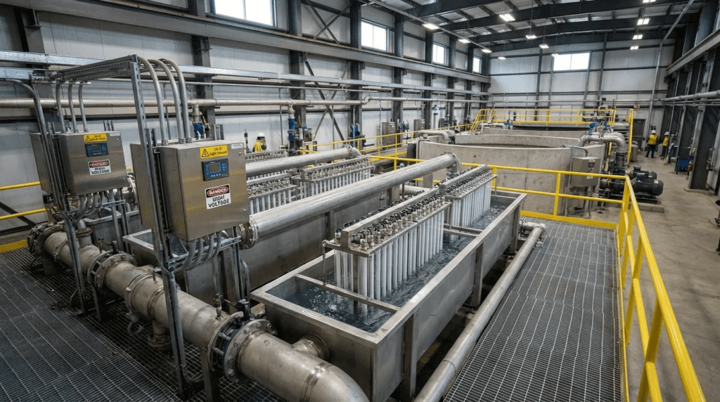
Ultraviolet (UV) Disinfection: Relies on UVC light (optimal at 254 nm) to penetrate microbial cell walls and dimerize DNA/RNA, preventing replication. Systems are typically open-channel (gravity flow) or closed-vessel (pressurized). The two main lamp technologies are:
- Low-Pressure High-Output (LPHO): Emits monochromatic light at 254 nm. Highly energy-efficient, long lamp life (typically 12,000+ hours), but lower output per lamp requires larger footprints and more lamps for high-flow applications.
- Medium-Pressure (MP): Emits polychromatic light across a broad spectrum. Extremely high output per lamp allows for a highly compact footprint, but they consume significantly more energy and have shorter lifespans (typically 4,000–8,000 hours). Usually reserved for space-constrained retrofit applications or advanced oxidation.
Ozone (O3) Disinfection: An incredibly powerful oxidant generated on-site by passing oxygen gas through a high-voltage electrical discharge (corona discharge). Ozone destroys cell walls through radical oxidation. A complete system requires a feed gas preparation unit (Liquid Oxygen [LOX] or Pressure Swing Adsorption [PSA]), the ozone generator, a contact basin with fine-bubble diffusers or side-stream venturi injection, and an off-gas ozone destruct unit. The process chemistry, dose determination, and contactor design are treated in depth under ozonation as a treatment process in its own right.
Peracetic Acid (PAA): An organic peroxide (CH3CO3H) supplied as an equilibrium mixture of acetic acid, hydrogen peroxide, and water. Unlike chlorine, PAA does not form harmful halogenated DBPs. It is a drop-in liquid chemical replacement for hypochlorite, utilizing similar metering pumps and contact basins, making it highly attractive for retrofits minimizing CAPEX.
Advanced Oxidation Processes (AOPs): Combines oxidants (e.g., UV + Hydrogen Peroxide, or Ozone + Hydrogen Peroxide) to generate hydroxyl radicals. These radicals are non-selective and extremely fast-reacting, designed not just to disinfect, but to destroy micro-pollutants, endocrine-disrupting compounds (EDCs), and pharmaceutical residues in water reuse scenarios. The reaction pathways, oxidant pairing, and scavenging behavior that govern these systems are covered under advanced oxidation processes.
Hydraulic & Process Performance
Hydraulics dictate the success of advanced disinfection. In UV open-channel systems, the approach velocity must be uniform. Poor velocity profiles lead to short-circuiting, where some pathogens pass through the reactor at high speeds receiving a sub-lethal dose, while others linger and waste energy. Engineers typically design for approach velocities between 1.5 to 3.0 ft/sec. Furthermore, downstream water level control (usually via counter-weighted flap gates or sharp-crested weirs) is mandatory to keep lamps strictly submerged regardless of flow rate.
For ozone and PAA, Contact Time (CT) is the governing parameter. Process performance relies on maximizing the Baffling Factor (T10/T) to approach plug-flow conditions. Dead zones in contact basins reduce the effective T10, requiring operators to overdose chemicals to meet permit limits.
Materials & Compatibility
Advanced oxidants are aggressive and require strict material selection protocols:
- Ozone: Dry ozone gas requires 316L Stainless Steel or specialized PTFE/Teflon piping. Wet ozone or dissolved ozone in water requires 316L SS. Ozone rapidly degrades natural rubber, standard EPDM, and PVC.
- PAA: Concentrated PAA (12-15%) is highly corrosive. Storage tanks are typically high-density cross-linked polyethylene (XLPE) or 316L SS. Piping should be Schedule 80 PVC or CPVC, PTFE, or 316L SS. Brass, copper, and carbon steel will catalyze the rapid degradation of PAA and must be strictly avoided.
- UV Systems: Wetted components are universally 316L SS or Duplex stainless steels for higher chloride environments. Quartz sleeves encase the lamps to isolate them from the water while maximizing UV transmittance.
Reliability, Redundancy & Common Failure Modes
Regulatory agencies generally mandate redundancy (N+1 configuration) for disinfection. In UV systems, this means an extra channel or an extra bank of lamps per channel capable of handling peak flow. Common UV failure modes include electronic ballast failures (often due to poor cooling/ventilation) and mechanical wiper system jamming.
Ozone systems most frequently fail due to feed gas quality. If moisture enters the corona discharge chamber (dew point higher than -60°C), it reacts with nitrogen (if using air or low-purity oxygen) to form nitric acid, destroying the expensive dielectrics. Solid redundancy in cooling water and gas preparation is essential.
Controls, Automation & SCADA Integration
Modern advanced disinfection systems utilize dynamic pacing to optimize OPEX:
- UV Flow-Pacing: SCADA monitors influent flow, UVT (via online analyzer), and lamp age/fouling. The PLC calculates the real-time UV dose and automatically dims ballasts or turns off entire lamp banks to match the required target dose (e.g., 30 mJ/cm²).
- Chemical Feed-Forward/Feed-Backward: PAA and Ozone systems use flow meters for feed-forward dosing, coupled with downstream residual analyzers for feed-backward trimming. This ensures the chemical demand is met without violating maximum residual discharge limits.
Lifecycle Cost Drivers
When selecting a technology, CAPEX and OPEX profiles differ drastically. PAA requires minimal CAPEX (simple tanks and metering pumps) but carries a high OPEX due to the recurring cost of bulk chemical delivery. UV requires moderate CAPEX and moderate-to-high OPEX (electricity, replacement lamps every 1-2 years, replacement ballasts). Ozone requires the highest CAPEX (generators, LOX storage, destruct units) and high OPEX (significant power consumption and intensive maintenance requirements).
Comparison Tables
The following tables provide an objective, specification-safe framework for comparing advanced disinfection technologies. Table 1 breaks down the technical attributes and maintenance profiles of each method. Table 2 provides an application fit matrix to assist engineers in quickly identifying the optimal technology based on site-specific constraints.
| Technology | Key Process Mechanisms | Primary Advantages | Limitations & Constraints | Typical Maintenance Profile |
|---|---|---|---|---|
| UV (LPHO) | Physical inactivation via 254 nm UVC light (DNA dimerization). | No chemical handling, no DBPs, minimal space, highly effective on Cryptosporidium. | Highly dependent on UVT. TSS/turbidity shields pathogens. High power draw. | Routine wiper fluid refills, lamp replacement (12,000 hrs), quartz sleeve cleaning/replacement. |
| Ozone (O3) | Chemical oxidation via on-site generated radical oxygen species. | Extremely powerful oxidant, improves effluent color/odor, increases dissolved oxygen. | Highest CAPEX. Complex generation/destruct equipment. Potential bromate formation. | Dielectric tube inspection/cleaning, chiller O&M, LOX system upkeep, safety sensor calibration. |
| Peracetic Acid (PAA) | Chemical oxidation via organic peroxide dosing. | Lowest CAPEX. Drop-in replacement for chlorine. No halogenated DBPs. | High ongoing chemical costs. Adds small amounts of BOD/acetic acid to effluent. | Pump tubing/stator replacement, venting maintenance, bulk tank inspection, residual analyzer calibration. |
| AOP (UV/H2O2) | Generates hydroxyl radicals via combination of oxidant and UV. | Destroys complex micro-pollutants and EDCs. Essential for Direct Potable Reuse. | High CAPEX and OPEX. Requires quenching of residual peroxide. Complex controls. | Combined maintenance of UV systems plus chemical dosing systems. |
| Application Scenario | UV Systems | Ozone | PAA | AOP |
|---|---|---|---|---|
| Small Municipal Plant (<5 MGD), Limited Budget | Excellent | Poor | Excellent (Retrofit) | Poor |
| Large Municipal Plant (>50 MGD) | Excellent | Good | Moderate (High OPEX) | N/A |
| High TSS / Low UVT Effluent | Poor | Moderate | Excellent | Poor |
| Direct/Indirect Potable Reuse (DPR/IPR) | Good (as barrier) | Excellent | Poor | Excellent |
| Strict THM/HAA Limits, Existing Chlorine Contact Basin | Moderate (needs demo) | Moderate (costly) | Excellent | Poor |
Engineer & Operator Field Notes
Commissioning & Acceptance Testing
Commissioning advanced disinfection systems is rigorous. For UV systems, Factory Acceptance Testing (FAT) usually verifies ballast panel programming and power distribution. However, the critical milestone is the on-site bioassay validation (if required by local regulators, e.g., Title 22). This involves spiking the influent with a known surrogate (like MS2 bacteriophage) and measuring log inactivation across various flow rates and power settings to verify the reactor’s computational fluid dynamics (CFD) model.
For ozone systems, performance verification must include mass transfer efficiency testing. Engineers measure the ozone concentration in the feed gas and the off-gas to calculate the amount of ozone successfully dissolved into the wastewater. Transfer efficiencies below 85-90% indicate poor diffuser performance or inadequate contactor depth.
Pro Tip: When commissioning PAA dosing systems, always verify the calibration of the online residual analyzers using a DPD drop-count titration or a handheld colorimeter. PAA analyzers are notorious for baseline drift during the first two weeks of operation.
Common Specification Mistakes
A frequent error in RFP/bid documents for UV systems is over-specifying peak flows without defining the minimum UV Transmittance concurrently. Specifying a peak wet weather flow (e.g., 20 MGD) at a high dry-weather UVT (e.g., 65%) will result in an undersized system, as wet weather events almost universally cause a crash in UVT due to I&I (Inflow and Infiltration) and clarifier washout.
Another common mistake with PAA systems is failing to account for off-gassing in the chemical feed lines. PAA naturally decomposes into acetic acid, water, and oxygen gas. If metering pumps and suction lines are not equipped with continuous automatic degassing valves, the pumps will vapor lock and fail to dose chemical, leading to a permit violation.
A third error is specifying an advanced technology without stating the validation basis. A UV reactor is only credited with the dose its third-party validation report supports, at the flow and transmittance ranges that report covers. A specification that names a target dose without naming the validation protocol and the acceptable operating envelope leaves the utility unable to reject a reactor validated under conditions it will never see.
O&M Burden & Strategy
Advanced disinfection shifts the O&M burden from chemical safety management (like SCBA gear for chlorine gas) to electrical and instrumentation maintenance. UV operators must manage an active inventory of lamps and ballasts. Lamp aging curves mean that even if a lamp hasn’t burned out, its output may drop to 70% after 12,000 hours, requiring scheduled group replacements to maintain permit compliance. Automated mechanical wipers must have their seals and wiper fluid (typically a mild food-grade acid like citric acid to prevent iron/calcium scale) checked monthly.
Ozone systems require predictive maintenance on cooling systems. A chiller failure will immediately trip the generator on high temperature. Regular infrared thermography on the generator power supply units is recommended to detect deteriorating electrical connections.
Troubleshooting Guide
- Symptom: Low UV dose alarm but flow is normal. Root Cause: Usually a fouled quartz sleeve or a drifted UV intensity sensor. Fix: Manually trigger a wiper cycle. Pull and clean the sensor. If unresolved, verify actual water UVT using a benchtop spectrophotometer.
- Symptom: PAA metering pumps running, but no residual detected. Root Cause: Vapor lock in the pump head, or unexpected high organic loading (scavengers) consuming the chemical instantly. Fix: Vent the pump head. Verify influent COD/BOD.
- Symptom: Ozone destruct unit high-temperature alarm. Root Cause: Catalyst degradation or moisture in the off-gas. Fix: Inspect the demister pad upstream of the destruct unit; replace the catalytic media (typically Carulite or similar transition metal oxide).
- Symptom: Compliance samples pass but dose readings sit near the alarm threshold. Root Cause: The system is operating with no margin, typically because lamp output has aged or transmittance has drifted down seasonally. Fix: Compare current sensor readings against the commissioning baseline, verify UVT independently, and schedule group lamp replacement before the next wet season rather than after the first violation.
Design Details & Calculations
Sizing Logic & Methodology
Proper sizing in Advanced Disinfection Technologies in Wastewater Treatment: A Complete Guide relies heavily on mathematical modeling and empirical water quality data.
UV Dose Calculation: UV dose is the product of intensity and time.
Where D is UV dose in mJ/cm², I is UV intensity in mW/cm², and t is retention time in the reactor in seconds. Because flow is turbulent, engineers use Point Source Summation (PSS) models and CFD to calculate the Reduction Equivalent Dose (RED). For secondary wastewater effluent, a typical design target is 30 to 40 mJ/cm² to achieve a 3-to-4 log reduction of fecal coliform or E. coli.
Chemical Disinfection (PAA/Ozone) CT Calculation: Chemical effectiveness is governed by the CT concept.
Where C is the residual disinfectant concentration at the end of the contact basin in mg/L, and T10 is the time in minutes that 90% of the water remains in the basin. T10 is calculated by taking the theoretical detention time (Volume divided by Flow) and multiplying it by the Baffling Factor (BF). A well-baffled serpentine basin may have a BF of 0.7, whereas an unbaffled tank might be 0.3.
Common Mistake: Never use theoretical detention time (V/Q) in place of T10 for permit calculations. Regulatory agencies will reject the design, and the system will chronically underperform due to short-circuiting.
Specification Checklist
When drafting specifications, engineers must include:
- Performance Criteria: Target organism, required log removal, peak flow rate, minimum UVT, maximum TSS.
- Validation: Requirement for third-party validation reports (e.g., NWRI, USEPA UVDGM) specific to the proposed lamp/reactor geometry.
- Automation: Dose-pacing algorithms, SCADA communication protocols (e.g., Modbus TCP/IP, Ethernet/IP).
- Spares: Require a minimum 10% spare inventory for lamps, quartz sleeves, ballasts, and O-rings to be delivered at commissioning.
- Water Quality Basis: A full year of UVT, TSS, and COD data at the design point, with the wet weather minimum stated separately from the annual average.
- Baffling Factor: For chemical contactors, the assumed BF and the tracer study protocol that will verify it at acceptance.
- Turndown: Minimum and maximum flow at which the system must deliver the target dose, with the control strategy across that range described.
Standards & Compliance
Designs must adhere to established industry frameworks. For UV in reuse applications, the NWRI (National Water Research Institute) Ultraviolet Disinfection Guidelines for Drinking Water and Water Reuse is the gold standard, often requiring a minimum dose of 80 mJ/cm² or 100 mJ/cm² depending on the upstream treatment train. For ozone, AWWA standards (such as AWWA B304 for liquid oxygen) dictate feed gas handling and safety.
- USEPA Ultraviolet Disinfection Guidance Manual (UVDGM): The federal reference for UV reactor validation and dose crediting.
- NWRI UV Guidelines: The reuse-focused framework governing minimum dose and validation in Title 22 and comparable programs.
- AWWA B304: Liquid Oxygen for Ozone Generation.
- NFPA 820: Fire Protection in Wastewater Treatment and Collection Facilities, governing electrical area classification in disinfection and chemical storage spaces.
- OSHA 29 CFR 1910.119: Process Safety Management, which applies to gas chlorine above threshold quantity and is frequently the driver behind a move to an advanced technology.
Frequently Asked Questions
What are advanced disinfection technologies in wastewater treatment?
Advanced Disinfection Technologies in Wastewater Treatment encompass alternatives to traditional chlorine gas and sodium hypochlorite. The primary technologies are Ultraviolet (UV) light, Ozone (O3), Peracetic Acid (PAA), and Advanced Oxidation Processes (AOPs). These methods are used to achieve strict pathogen log-removal requirements while avoiding the generation of toxic disinfection byproducts (DBPs) and eliminating the need for dechlorination.
How do you select the right advanced disinfection system?
Selection is based on the plant’s effluent water quality (specifically UV Transmittance, TSS, and COD), existing infrastructure, capital budget, and regulatory limits. UV is preferred for low-turbidity effluents where chemical handling is undesirable. PAA is often selected for retrofitting existing chlorine contact basins with minimal CAPEX. Ozone is utilized when additional oxidation (color removal, CEC destruction) is required.
What is the difference between UV and Ozone disinfection?
UV uses light waves (254 nm) to physically alter pathogen DNA, preventing replication without adding anything to the water. Ozone is a highly reactive gas generated on-site that dissolves into the water to chemically rupture cell walls via oxidation. UV relies on water clarity (UVT), while ozone is highly sensitive to the water’s organic chemical demand (scavengers).
How much does an advanced disinfection system cost?
Costs vary widely by capacity and technology. For a 10 MGD municipal plant, a complete UV system CAPEX typically ranges from $500K to $1.2M. PAA equipment is much cheaper ($100K–$300K for tanks and dosing skids) but carries a high recurring chemical cost. Ozone is the most capital-intensive, often exceeding $2M–$4M for a 10 MGD facility when factoring in LOX storage, generators, and destruct systems. All figures are order-of-magnitude planning numbers and should be replaced with budgetary quotes before they enter a capital plan.
Why do UV systems fail or underperform?
The most common cause of UV underperformance is lamp sleeve fouling due to iron, hardness, or biological growth, which blocks the light. Another major cause is hydraulic short-circuiting due to poor channel design or poor water-level control. Finally, rapid drops in influent UVT (e.g., from an upstream clarifier upset) will cause the required dose to plummet if the system maxes out its power output.
What are the safety concerns with Peracetic Acid (PAA)?
While PAA avoids halogenated DBPs, the concentrated chemical (typically 12% to 15%) is highly corrosive and a strong oxidizer. It can cause severe skin burns and eye damage. Furthermore, it continuously off-gasses oxygen. If stored in sealed piping without pressure relief or automatic degassing valves, it can cause pipe rupture or vapor lock in metering pumps.
What are the maintenance requirements for ozone generators?
Ozone systems require meticulous maintenance to protect the electrical components. Routine tasks include inspecting and cleaning the dielectric tubes, replacing desiccant or maintaining LOX vaporizers, verifying cooling chiller performance, and calibrating ambient ozone safety sensors. Poor feed-gas dew point control is the leading cause of catastrophic dielectric failure.
Where do emerging technologies like photocatalysis and nanomaterials fit?
Not yet in a compliance-critical disinfection role at municipal scale. UV, ozone, and PAA have validation protocols, regulatory acceptance, and installed reference bases that emerging methods do not. Photocatalysis, electron beam irradiation, engineered adsorbents, and nanomaterials are being developed for problems the established technologies handle poorly, principally micropollutants, PFAS, and nutrient recovery, rather than as replacements for the pathogen barrier. The practical guidance is to keep them in view for a specific contaminant problem, evaluate them on pilot data from a comparable water matrix, and not to place a permit obligation on a technology without a validation pathway.
Conclusion
Key Takeaways
- Match Technology to Water Matrix: UV requires high UVT (>65%) and low TSS; PAA handles lower UVT/high TSS better but introduces bulk chemical OPEX; Ozone is powerful but sensitive to organic scavengers.
- Hydraulics are Critical: Both UV and chemical systems fail without proper hydraulics. Ensure uniform approach velocities (1.5–3.0 ft/s) for UV, and maximize baffling factors (T10/T) for chemical contactors.
- Dose Control Optimizes OPEX: Utilize advanced PLC/SCADA integration for UV flow/UVT-pacing and chemical feed-forward/residual-trimming to prevent gross energy or chemical waste.
- CAPEX vs. OPEX Tradeoff: PAA offers the lowest capital cost for retrofits but high chemical OPEX. UV and Ozone require significant upfront capital and routine mechanical/electrical maintenance.
- Redundancy is Mandatory: Always design with N+1 redundancy for peak flow scenarios to prevent permit violations during extreme wet weather events or equipment failure.
- Specify the Validation Basis: A reactor is credited only with the dose its third-party validation supports, across the flow and transmittance range that validation covers.
- Size on Wet Weather, Not Annual Average: Transmittance crashes during the events that also bring peak flow, and a system sized on dry-weather UVT will be short exactly when it matters.
Approaching Advanced Disinfection Technologies in Wastewater Treatment: A Complete Guide requires engineers and utility operators to balance capital budgets against long-term operational realities. As the industry moves away from traditional chlorine due to safety risks and DBP regulations, the burden shifts toward highly engineered, water-quality-dependent technologies.
The decision framework for real-world projects must start with extensive water quality profiling. A year of historical UVT, TSS, and COD data is highly recommended before committing to a technology. For small-to-medium plants looking to eliminate chlorine gas with minimal capital outlay, PAA has proven to be a highly effective, drop-in replacement, provided the supply chain economics make sense for the utility’s location. For larger facilities with good secondary clarification, UV disinfection remains the industry standard, offering a predictable, chemical-free process, provided that engineers strictly adhere to hydraulic design best practices.
Ozone and AOPs, while complex and expensive, are increasingly indispensable. As regulations evolve toward water reuse and the eradication of contaminants of emerging concern (CECs) like PFAS, microplastics, and pharmaceuticals, these aggressive oxidation technologies will become standard fixtures in advanced water purification facilities.
Ultimately, successful implementation of advanced disinfection requires robust specification, rigorous third-party validation, and an operator-centric design philosophy. By designing for maintainability, ensuring easy access to lamp banks, implementing reliable automated wiping systems, providing fail-safe chemical degassing, and installing redundant cooling for high-voltage generators, engineers can deliver resilient facilities capable of meeting the stringent discharge and reuse permits of the future.