
Chemical Feed Systems in Water Treatment: Design and Selection
INTRODUCTION
In municipal and industrial water infrastructure, an unyielding truth governs plant reliability: a multimillion-dollar treatment facility will routinely fail to meet compliance if a $5,000 chemical dosing skid underperforms. When addressing Chemical Feed Systems in Water Treatment: Design and Selection, engineers are often forced to balance severe operational extremes. These systems must consistently deliver highly accurate, micro-volume dosages of aggressive, off-gassing, or highly viscous fluids into dynamically changing process flows.
Historically, chemical feed systems have been relegated to an afterthought in standard facility design—viewed merely as ancillary equipment to larger unit processes like clarifiers, filters, or bioreactors. However, inappropriate pump technology selection, overlooked material incompatibilities, or poorly designed suction hydraulics frequently result in catastrophic vapor lock, chemical leaks, or uncontrollable process oscillations. Over-specification leads to massive turndown limitations, while under-specification results in premature equipment failure and intense operator maintenance burdens.
Chemical feed systems are utilized across nearly every unit process in municipal drinking water, wastewater, and industrial effluent treatment. Their applications range from dosing coagulants (e.g., aluminum sulfate, ferric chloride) and polymers for solids separation, to injecting disinfectants (e.g., sodium hypochlorite), pH adjusters (e.g., sulfuric acid, sodium hydroxide), and specialized corrosion inhibitors. That breadth is why feed system design sits upstream of so much else: the oxidant dose that determines whether disinfection in wastewater treatment achieves its target residual is only as reliable as the pump delivering it.
This comprehensive article will provide design engineers, plant directors, and utility operators with a technical framework for evaluating, sizing, and specifying liquid and dry chemical feed systems. By focusing on real-world hydraulic constraints, technological limitations, and lifecycle maintainability, this guide will help professionals navigate the complex landscape of chemical feed system engineering.
CHEMICAL FEED SYSTEM SUBCATEGORIES
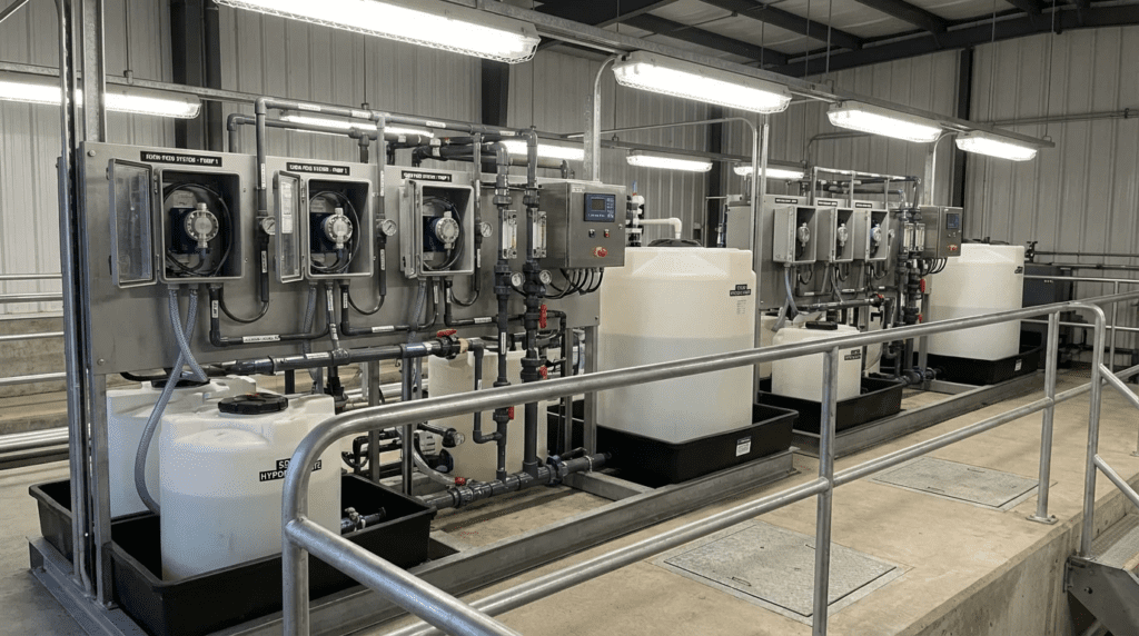
A chemical feed system is a package, not a pump. Bulk storage, secondary containment, transfer and day tanks, dilution and makedown where required, the metering pump itself, the ancillary valve train, the injection point, and the control loop are all part of it, and a failure anywhere in that chain presents as a dosing problem. It is also worth being clear about the boundary between the equipment and the processes it serves: the chemistry of what you are dosing and why is covered separately under chemical treatment of wastewater, while the two highest-volume applications in most plants — coagulation and flocculation and pH and alkalinity control — each set their own accuracy, turndown, and material requirements back onto the feed equipment described here.
The subcategories below cover the practice, the hardware, and the supplier landscape.
Chemical Dosing Practice
Before equipment selection comes the question of what good dosing practice actually looks like in operation. Our coverage of chemical dosing practices addresses the operational discipline that separates a feed system that holds its setpoint from one that drifts: calibration frequency and method, dose verification against process results rather than against pump settings, record keeping that makes a drift detectable before it becomes a compliance event, and the handling procedures that govern tank changeover and line flushing. Most dosing accuracy is lost to routine rather than to design. A pump specified to one percent linearity and never calibrated against a drawdown column is delivering an unknown dose, and the unknown grows quietly as check valves wear.
Chemical Dosing Equipment
The hardware side spans more than the pump. Our article on chemical dosing equipment covers the components that make up a working feed installation: storage tanks and their level instrumentation, transfer and day tank arrangements, the calibration column, pressure relief and back pressure valves, pulsation dampeners, injection quills and corporation stops, and the leak detection and containment hardware that turns a failure into an alarm rather than a spill. Specifying the pump and leaving the ancillaries to the installing contractor is one of the more reliable ways to produce a skid that meters badly, and several of the failure modes described later in this article trace directly to a missing or misplaced component from that list.
Equipment Manufacturers and Product Selection
The chemical feed market divides between pump specialists, tank and containment manufacturers, and packaged skid integrators, and few suppliers are strong across all three. Our review of the top OEMs for chemical feed and storage systems covers the major suppliers of feed and storage equipment serving water and wastewater. Supplier selection carries unusual weight in this category because the consumables are constant: diaphragms, check balls and seats, peristaltic tubes and hoses, and elastomers are all wear parts on a months-to-years cycle, and parts availability over a fifteen-year installation life matters more than any headline accuracy figure. Ask what the liquid end repair kit costs and how quickly it ships before comparing pump curves.
Vendor Comparison and Trade-Offs
Head-to-head evaluation is where most procurement decisions are actually settled. Our ProMinent and Assmann comparison for chemical feed and storage works through the trade-offs between two suppliers approaching the same installation from different directions — one from metering pump and controller engineering, the other from polyethylene tank and containment manufacturing. That split is characteristic of the market and worth understanding before a bid package is written: a specification drafted around pump performance alone will be answered very differently by a pump house than by a tank house, and a packaged skid procurement needs both competencies represented or explicitly assigned.
CORE TECHNICAL CONTENT
Operating Conditions & Duty Requirements
The foundation of chemical feed system design is a rigorous analysis of operating conditions. The primary challenge engineers face is defining the required turndown ratio. Turndown is the ratio of the maximum required chemical feed rate to the minimum required feed rate. It is driven by two independent variables multiplying against each other: plant flow variations and chemical dosage variations.
For example, if a water treatment plant experiences a peak summer flow of 20 MGD and a minimum winter night flow of 2 MGD (a 10:1 flow turndown), and the required coagulant dose varies from a low of 5 mg/L in winter to a high of 25 mg/L during storm events (a 5:1 dose turndown), the chemical feed system must accommodate a total turndown ratio of 50:1. Standard motor-driven metering pumps operating on VFDs typically only provide a 10:1 turndown without stalling or losing accuracy. Failing to recognize this requirement is a leading cause of feed system failure, necessitating the implementation of dual-pump configurations (e.g., high-flow and low-flow pumps) to cover the entire operational envelope.
Furthermore, engineers must evaluate the physical properties of the chemical. Viscosity significantly impacts the Net Positive Suction Head required (NPSHr) by the metering pump. Highly viscous neat polymers (often exceeding 5,000 cP) cannot be pumped with standard diaphragm pumps and require positive displacement technologies that impart lower shear forces, such as progressive cavity or specialized gear pumps. Conversely, low-viscosity, high-vapor-pressure chemicals like sodium hypochlorite are prone to off-gassing, requiring specialized hydraulic considerations to prevent vapor lock.
Types, Configurations & Technologies
Within the scope of Chemical Feed Systems in Water Treatment: Design and Selection, identifying the correct pump technology is paramount. The primary technologies utilized include:
- Solenoid-Driven Diaphragm Pumps: Utilized for low-flow, high-pressure applications. A magnetic solenoid acts on an armature attached to a Teflon diaphragm. They offer excellent turndown (often up to 1000:1 via pulse frequency control) but operate in discrete, highly pulsating strokes that require significant pulsation dampening.
- Motor-Driven Mechanical/Hydraulic Diaphragm Pumps: The industry standard for continuous, mid-to-high capacity dosing. Hydraulic diaphragms offer built-in relief protection and superior longevity compared to mechanical diaphragms. They are highly accurate but suffer from limited turndown on purely VFD-based speed control without manual stroke length adjustment.
- Peristaltic (Hose/Tube) Pumps: Increasingly popular for off-gassing fluids (like sodium hypochlorite) and shear-sensitive or viscous fluids (like polymers). Because they lack internal check valves, vapor lock is virtually eliminated. However, they rely on the compression of an elastomeric tube, making tube degradation and replacement a primary, ongoing maintenance requirement.
- Progressive Cavity (PC) Pumps: Utilized primarily for highly viscous polymers or slurry feeds (e.g., lime slurry, powdered activated carbon). They provide smooth, non-pulsating flow but have a larger physical footprint, run-dry vulnerabilities, and high replacement costs for stators and rotors.
- Dry Chemical Feeders: Used for bulk dry chemicals (lime, potassium permanganate, fluoride). Volumetric feeders discharge a set volume per revolution, while gravimetric feeders utilize load cells to dose by precise mass, offering superior accuracy (typically ±1%) at a higher capital cost.
Materials & Compatibility
Chemical compatibility extends beyond the pump wetted parts to encompass piping, valves, gaskets, and storage tanks. Specifying an incompatible material leads to rapid catastrophic failure, environmental spills, and severe operator safety risks.
- Sodium Hypochlorite (NaOCl): Highly oxidizing and alkaline. Typically requires PVC, CPVC, or PVDF piping. Viton or EPDM elastomers are common, but Titanium is often required for metallic components (like pump check valve springs). Avoid stainless steel, which will corrode rapidly.
- Sulfuric Acid (H2SO4): Behavior depends heavily on concentration. Concentrated sulfuric acid (>93%) can be stored in carbon steel tanks but will rapidly destroy PVC. Dilute sulfuric acid is highly corrosive to carbon steel and requires Alloy 20, PTFE, or PVDF.
- Ferric Chloride (FeCl3): Extremely corrosive. Non-metallic systems (FRP, PVC, PVDF, PTFE) are mandatory. Any exposed carbon or stainless steel in the vicinity will suffer vapor corrosion.
- Sodium Hydroxide / Caustic Soda (NaOH): Commonly causes issues not due to corrosion, but due to freezing/crystallization. 50% NaOH freezes at roughly 54°F (12°C). Feed systems must utilize heat tracing and insulation, or the utility must dilute to 25% (which freezes much lower).
Installation, Constructability & Space Requirements
Chemical feed skids require meticulous spatial planning. Pumps must be located as close to the storage tanks as possible to minimize suction line length. Flooded suction is always the preferred design, placing the pump centerline below the minimum liquid level of the storage tank. When suction lift cannot be avoided, engineers must carefully calculate the Net Positive Suction Head available (NPSHa), factoring in vapor pressure, friction losses, and specific gravity.
Containment is a critical constructability factor. Regulatory standards typically require secondary containment capable of holding 110% of the largest single tank’s volume within the containment area. Furthermore, incompatible chemicals (e.g., an acid and a base, or an acid and hypochlorite which produce toxic chlorine gas) must be stored in physically segregated containment basins with separate drainage systems.
Controls, Automation & SCADA Integration
Modern chemical feed systems rely heavily on automated pacing. The two most common control strategies are:
- Flow-Paced Control: The chemical feed pump speed is directly proportional to the primary process flow meter (e.g., an influent magnetic flow meter sends a 4-20mA signal to the pump VFD). The operator inputs a desired dose (mg/L), and the PLC calculates the required pump output.
- Compound-Loop Control: A more advanced strategy combining flow-pacing with process feedback. For example, a chlorine dosing pump is roughly paced by plant flow, but a downstream chlorine residual analyzer provides a secondary feedback loop (PID control) to trim the pump speed up or down to maintain an exact residual setpoint.
To verify actual chemical delivery, mass flow meters (Coriolis) or specialized low-flow electromagnetic meters are increasingly installed on the discharge piping. This provides SCADA with positive verification that chemical is flowing, rather than just verifying that the pump motor is running.
COMPARISON TABLES
The following tables provide an unbiased engineering matrix for evaluating Chemical Feed Systems in Water Treatment: Design and Selection. Table 1 compares the primary liquid metering pump technologies, while Table 2 outlines the application fit matrix for common water and wastewater chemicals.
| Technology Type | Primary Strengths | Typical Applications | Hydraulic Limitations | Maintenance Profile |
|---|---|---|---|---|
| Solenoid Diaphragm | Low capital cost, exceptional turndown, footprint, simple pulse control. | Low-flow wellheads, small package plants, anti-scalant feed. | Limited max capacity (typically < 20 GPH). Highly pulsating flow. Susceptible to vapor lock. | Low. Occasional check valve cleaning and diaphragm replacement. |
| Motor-Driven Diaphragm (Hydraulic) | High pressure capability (up to 3000+ psi), high accuracy, longevity. | High-pressure injection, primary coagulant feed, large municipal plants. | Requires complex ancillary valves (PRV, BPV, dampeners). Poor turndown without stroke adjustment. | Moderate. Oil changes, check valve rebuilds, hydraulic system bleeding. |
| Peristaltic (Tube/Hose) | No vapor lock (no check valves), handles high viscosity and suspended solids. | Sodium hypochlorite, neat polymers, lime slurries, PAC. | Pulsating flow. Hose limits maximum discharge pressure (typically < 125 psi). | High frequency / Low difficulty. Routine tube/hose replacement based on operating hours. |
| Progressive Cavity (PC) | Smooth, continuous, non-pulsating flow. Unmatched for high viscosity. | Dewatering polymer feed, heavy sludge conditioning. | Run-dry will destroy stator in minutes. Large physical footprint. | High cost / High difficulty. Stator and rotor replacements require space and specialized tools. |
| Chemical Service | Recommended Pump Type(s) | Primary Material Match (Wetted) | Critical Design Constraints & Considerations |
|---|---|---|---|
| Sodium Hypochlorite | Peristaltic, Degassing Diaphragm | PVC, CPVC, Titanium, PTFE | Severe off-gassing. Always design flooded suction. Avoid traps where gas can accumulate. Protect from UV light. |
| Alum / Ferric (Coagulants) | Motor-Driven Diaphragm | PVC, PVDF, PTFE, Hastelloy C | Ferric is highly corrosive. Alum can crystallize if temperature drops. Use pulsation dampeners to smooth flow. |
| Liquid Polymer (Neat) | Progressive Cavity, Peristaltic | Stainless Steel (316), PVC | High viscosity (up to 10,000 cP). Cannot use centrifugal or standard diaphragm pumps. Requires low-shear handling. |
| Sulfuric Acid (Dilute) | Motor-Driven Diaphragm | PVDF, PTFE, Alloy 20 | Extreme exothermic reaction if mixed with water incorrectly. Double containment piping is highly recommended. |
| Sodium Hydroxide (Caustic) | Solenoid or Motor Diaphragm | CPVC, EPDM, 316 SS | Crystallization and freezing are the primary threats. Heat tracing on piping and tank insulation is critical for 50% solutions. |
ENGINEER & OPERATOR FIELD NOTES
Commissioning & Acceptance Testing
Commissioning chemical feed systems requires methodical verification to ensure specified accuracies (typically ±1% to ±2% of steady-state flow) are met. The most critical field procedure is the draw-down test using a calibration column. Every chemical feed skid must be designed with a clear, graduated calibration cylinder installed on the suction side, complete with isolation valves.
During Site Acceptance Testing (SAT), operators isolate the bulk tank and allow the pump to draw purely from the calibration column for a set time (e.g., 60 seconds). The volumetric displacement is observed and compared against the SCADA output to generate a calibration curve. Engineers must specify that this test is repeated at 10%, 50%, and 100% of pump capacity to verify linearity and turndown capabilities.
Common Specification Mistakes
When drafting documentation for Chemical Feed Systems in Water Treatment: Design and Selection, engineers frequently make several recurring errors:
- Omitting Backpressure Valves (BPV): Metering pumps require a positive pressure differential to seat their check valves properly. If the discharge point (e.g., an open channel) is at atmospheric pressure and the suction tank is full (elevated head), chemical can siphon directly through the pump. A BPV provides an artificial, spring-loaded restriction (typically set at 30-50 psi) to ensure accurate dosing and prevent siphoning.
- Improper Pressure Relief Valve (PRV) Routing: Because diaphragm and PC pumps are positive displacement, discharging against a closed valve will cause pipe rupture in seconds. PRVs must be installed immediately after the pump discharge. Crucially, the PRV discharge must be piped safely back to the bulk storage tank, NOT back into the pump suction line, as discharging into the suction line can cause air entrainment or heat buildup.
- Ignoring Suction Line Hydraulics: Engineers often match the suction pipe diameter to the pump inlet connection size. This is a mistake for pulsating pumps. The peak instantaneous flow during the suction stroke of a motor-driven diaphragm pump is mathematically equivalent to roughly 3.14 times the average flow rate. Suction piping must be oversized by 1-2 pipe sizes to prevent cavitation.
If using a mechanical diaphragm pump, specify an accumulator/pulsation dampener on the discharge piping. Charge the dampener with compressed air or nitrogen to 80% of the anticipated line pressure. This transforms the destructive pulsating “slugs” of chemical into a smooth, continuous flow, protecting downstream piping from water hammer and improving flow meter accuracy.
A dial position, a stroke percentage, or a SCADA output is a command, not a measurement. Worn check valves, a drifting back pressure setting, partial vapor lock, or a chemical delivered at a different concentration than the last load will all change the delivered dose while the pump setting stays exactly where the operator left it. This is why a calibration column is not optional equipment and why dose verification belongs against process results rather than against the setpoint. If a plant is adjusting stroke length to chase a residual, the underlying question is what changed, and the answer is almost never that the pump needed a higher setting.
O&M Burden & Strategy
The total lifecycle cost (TCO) of a chemical feed system is rarely driven by the capital cost of the pump; it is dominated by O&M labor and spare parts. An effective maintenance strategy requires maintaining critical spares on site. For diaphragm pumps, a complete “liquid end repair kit” (diaphragms, check valve balls, seats, and o-rings) must be kept in inventory. Annual preventative maintenance (PM) should include oil changes for motor-driven pumps and complete liquid end rebuilds.
For peristaltic pumps, O&M strategy revolves entirely around tube life. Tube failure is inevitable and should be preempted. If a hose typically lasts 2,000 hours in a specific application, operators should schedule a preventative replacement at 1,800 hours. The skid must include a leak detection sensor within the pump housing to alarm SCADA and shut down the pump the moment a tube ruptures.
Troubleshooting Guide
When chemical feed systems fail, operators should follow a diagnostic hierarchy:
- Motor runs, but no flow (Loss of Prime): Check for empty suction tank, closed isolation valve, or vapor lock. If vapor lock is suspected, open the degassing/bleed valve. Inspect suction check valve for debris.
- Erratic or lower-than-expected flow: Conduct a draw-down calibration. If flow is low, the likely culprit is worn check valves allowing backflow during the discharge stroke. Inspect check balls for scoring or particulate buildup. Ensure the BPV is set properly (at least 15 psi higher than suction pressure).
- Rapid tube failure (Peristaltic): Check for excessive discharge pressure or improper shimming/compression settings on the pump rotor. Ensure the tube material is chemically compatible.
- Dose drifts downward over weeks at a fixed setting: Almost always progressive check valve wear or seat scaling. Verify against the calibration column before increasing the setting, because raising stroke or speed to compensate masks the fault and accelerates the wear producing it.
- Chemical appears in the containment basin with no visible leak: Inspect the pressure relief valve and its discharge routing. A PRV relieving intermittently because the back pressure valve is set too high, or piped to a drain rather than back to the tank, will empty a day tank slowly and without an obvious source.
DESIGN DETAILS & CALCULATIONS
Sizing Logic & Methodology
Properly sizing a chemical feed pump requires converting process parameters (flow and dose) into physical volumetric pump output. The fundamental mass balance equation for water treatment is:
Pounds per Day (lbs/day) = Flow (MGD) × Dose (mg/L) × 8.34 lbs/gal
However, metering pumps are rated in Gallons Per Hour (GPH) or Milliliters Per Minute (mL/min), and liquid chemicals are delivered as aqueous solutions, not pure active ingredients. The sizing methodology follows these steps:
- Calculate Peak lbs/day of Active Chemical: Using the maximum anticipated plant flow and maximum anticipated dose.
- Convert to lbs/day of Solution: Divide the active lbs/day by the chemical concentration (expressed as a decimal).
- Convert to Volumetric Flow (GPD and GPH): Divide the solution lbs/day by the exact weight of the solution per gallon (which is 8.34 lbs/gal × Specific Gravity of the chemical).
Worked Example: Sizing an Aluminum Sulfate (Alum) Pump
- Design Parameters: Max Plant Flow = 5.0 MGD; Max Alum Dose = 40 mg/L; Alum Concentration = 48.5%; Alum Specific Gravity = 1.33.
- Step 1: Peak Active Alum = 5.0 MGD × 40 mg/L × 8.34 = 1,668 lbs/day.
- Step 2: Solution Alum Required = 1,668 / 0.485 = 3,439 lbs/day of liquid solution.
- Step 3: Weight of Alum Solution = 8.34 lbs/gal × 1.33 = 11.09 lbs/gal.
- Step 4: Volumetric Flow = 3,439 lbs/day / 11.09 lbs/gal = 310 Gallons Per Day (GPD).
- Step 5: Convert to GPH = 310 GPD / 24 hours = 12.9 GPH.
Safety Factor: A standard engineering rule of thumb is to size the pump so that this maximum calculated flow (12.9 GPH) represents 80% to 85% of the pump’s total capacity. Therefore, a pump rated for approximately 15 to 16 GPH would be specified. This allows for chemical degradation over time and ensures the pump isn’t operating continuously at its absolute maximum limit.
Checking the low end: the same calculation must be repeated at minimum plant flow and minimum dose, because that result determines whether one pump can cover the range at all. Running the alum example above at a 1.0 MGD night flow and a 10 mg/L winter dose gives 83 lbs/day active, 171 lbs/day of solution, and roughly 0.64 GPH — about 4 percent of the 16 GPH pump selected for the peak. No single metering pump holds stated accuracy at 4 percent of capacity, which is precisely the dual-pump situation described in the turndown discussion above. Size for the peak, then check the minimum before committing to a single unit.
Specification Checklist
When drafting procurement specifications, ensure the following ancillaries and parameters are explicitly demanded:
- Calibration Columns: Clear PVC or Borosilicate glass, sized for a 1-minute drawdown at maximum pump capacity.
- Pressure Relief Valve (PRV): Externally adjustable, piped back to the storage tank.
- Backpressure Valve (BPV): Adjustable diaphragm style, installed downstream of the pulsation dampener.
- Pulsation Dampener: Sized for at least 26 times the per-stroke displacement volume of the pump (for single simplex pumps).
- Y-Strainer: Installed on the suction line to protect check valves from debris (Note: omit strainers for neat polymer or lime slurry, as they will blind immediately).
- Minimum Feed Rate: State the calculated minimum dose condition alongside the maximum, and require the supplier to confirm stated accuracy at that point rather than at rated capacity only.
- Secondary Containment: Volume, material, segregation from incompatible chemicals, and leak detection with SCADA alarm.
- Injection Assembly: Injection quill or corporation stop with isolation, sized and located to avoid deposition at the injection point and to permit removal under pressure where required.
Standards & Compliance
Chemical feed systems must comply with specific regional and industry standards. In North America, the Ten States Standards (Recommended Standards for Water Works) dictates minimum requirements for redundancy (standby pumps are universally required), day tank volumes, and containment. Materials must adhere to NSF/ANSI Standard 61 for drinking water system components to ensure no harmful contaminants leach from the piping or pump materials into the potable water supply. Electrical panels and controls must bear UL 508A listing for industrial control panels, particularly in environments requiring NEMA 4X (corrosion resistant/washdown) enclosures.
Two further compliance layers are easy to miss because they sit outside the water standards. NSF/ANSI 372 governs lead content in drinking water contact components and applies alongside Standard 61. And where gaseous chlorine or anhydrous ammonia is stored above threshold quantities, the installation falls under OSHA Process Safety Management and EPA Risk Management Program requirements, which impose process hazard analysis, mechanical integrity, and management of change obligations on the feed system. That regulatory burden is one of the principal reasons utilities have converted from gas chlorine to hypochlorite, and it should be weighed at the concept stage rather than discovered during permitting.
FAQ SECTION
What is the difference between a diaphragm pump and a peristaltic pump in chemical feed?
A diaphragm pump utilizes a reciprocating membrane and one-way check valves to push fluid, making it highly accurate and suitable for high pressures. A peristaltic pump uses a rotating shoe or roller to squeeze a flexible tube, pushing the fluid forward. Peristaltic pumps have no check valves, making them immune to vapor lock and ideal for off-gassing chemicals like sodium hypochlorite or highly viscous polymers, though they require more frequent maintenance for tube replacement.
How do you select the correct sizing for Chemical Feed Systems in Water Treatment: Design and Selection?
Sizing involves calculating the mass feed rate using the formula: Flow (MGD) × Dose (mg/L) × 8.34 = lbs/day. This mass is then divided by the chemical concentration percentage and specific gravity to determine volumetric flow (Gallons Per Hour). Finally, engineers apply an 80-85% safety factor so the pump operates efficiently without running at 100% capacity continuously.
Why does my sodium hypochlorite feed pump keep losing prime?
Sodium hypochlorite naturally decomposes over time, creating oxygen gas bubbles. If the pump is idle or running at a very low stroke rate, this gas accumulates in the pump head. Because gas is compressible, standard diaphragm pumps cannot generate enough pressure to open the discharge check valve, resulting in vapor lock. Solutions include flooded suction, degassing valves, or switching to peristaltic pump technology.
What is a backpressure valve and why is it necessary?
A backpressure valve provides artificial, steady resistance on the discharge side of a positive displacement pump. It prevents chemical from siphoning through the pump if the discharge point is at a lower elevation than the suction tank. It also ensures the pump’s internal check valves seat firmly on every stroke, which is critical for maintaining dosing accuracy.
How often should chemical metering pumps be maintained or inspected?
Routine visual inspections (checking for leaks, verifying flow on SCADA) should be performed daily. Preventative maintenance, such as rebuilding the liquid end of a diaphragm pump (replacing diaphragms, check balls, o-rings) or changing gear oil, is typically scheduled annually or every 4,000-8,000 operating hours. Peristaltic pump tubes require replacement based on a strict operational-hour schedule specific to the pressure and RPM.
What are the common failure modes for chemical feed systems?
Common failures include vapor lock (gas accumulation), check valve failure (caused by debris or scaling), ruptured diaphragms or peristaltic tubes, and piping leaks due to chemical incompatibility (e.g., using stainless steel with ferric chloride). Over-pressurization due to closed downstream valves without proper pressure relief protection is a severe and common mechanical failure.
What is the typical lifecycle cost difference between peristaltic and diaphragm pumps?
Solenoid diaphragm pumps have lower initial capital costs but can suffer from vapor lock downtime. Motor-driven diaphragm pumps have high capital costs but excellent longevity and low O&M costs if properly maintained. Peristaltic pumps have moderate capital costs but higher ongoing OPEX due to the recurring expense of replacing specialized elastomeric tubes/hoses multiple times per year.
How much day tank and bulk storage volume should be provided?
Bulk storage is normally sized on delivery logistics and chemical shelf life together: enough to accept a full tanker load with working volume remaining, but not so much that the chemical degrades before it is used. Sodium hypochlorite is the constraining case, losing strength measurably over weeks at warm temperatures, which argues for smaller inventories and more frequent deliveries rather than the reverse. Day tanks serve a different purpose, limiting the volume that can be released in a single failure and providing a measurable inventory against which daily usage can be reconciled. Ten States Standards sets minimum expectations for both; a usage reconciliation against day tank level is also the simplest available check that the delivered dose matches the intended one.
Should chemical be fed neat or diluted?
It depends on the chemical and on what the dilution is meant to achieve. Dilution raises the volumetric feed rate, which improves metering accuracy at low doses and can bring a duty inside a single pump’s turndown range instead of requiring two. It also improves mixing at the injection point for chemicals that would otherwise enter as a concentrated stream. Against that, dilution water adds equipment, a potential contamination path, and in the case of polymer a makedown system with its own aging and mixing requirements. Some chemicals should not be diluted casually at all: adding water to concentrated sulfuric acid reverses the correct mixing order and is dangerous, and diluted hypochlorite loses strength faster than concentrated. Decide it deliberately rather than inheriting it from the last project.
CONCLUSION
Key Takeaways
- Turndown dictates technology: A total turndown requirement exceeding 10:1 typically necessitates either advanced pulse-control pumps, manual stroke adjustment, or a dual-pump (High/Low) configuration.
- Off-gassing requires specific hydraulics: Sodium hypochlorite and similar chemicals demand flooded suction, vent valves, or peristaltic technology to prevent severe vapor lock.
- Ancillaries are non-negotiable: Backpressure valves, pressure relief valves routed to the tank, pulsation dampeners, and calibration columns are critical to safety and accuracy.
- Match materials to the chemical: Consult strict chemical compatibility charts. A single incompatible o-ring can cause total system failure.
- Always calculate by mass, specify by volume: Convert the required lbs/day into GPH using the exact concentration and specific gravity of the chemical delivered to site.
- Check the minimum as carefully as the maximum: The low-flow, low-dose condition decides whether one pump can serve the duty, and it is the calculation most often skipped.
Approaching Chemical Feed Systems in Water Treatment: Design and Selection requires engineers and operators to shift their focus from the macro-scale plant hydraulics down to the micro-scale realities of positive displacement pumping. A successfully designed system balances the harsh realities of chemical properties—such as corrosion, viscosity, and off-gassing—with the strict accuracy and reliability demands of regulatory compliance.
When developing a decision framework for real-world projects, the first step must always be defining the operational envelope: the minimum and maximum plant flows intersecting with the minimum and maximum required chemical dosages. This sets the turndown criteria. From there, engineers must prioritize pump technology selection not based on upfront capital costs, but on hydraulic suitability and the utility’s maintenance culture. A facility with limited maintenance staff may prefer the rapid, predictable tube swaps of a peristaltic pump over the complex, albeit infrequent, rebuilds of a hydraulic diaphragm pump.
It is strongly recommended to involve chemical feed specialists or pump manufacturers early in the design phase, particularly when dealing with non-Newtonian fluids like neat polymers, or when space constraints force complex suction lift scenarios. While it is tempting to view chemical feed as a simple “plug-and-play” skid, the intricate dependencies between the pump, its ancillaries, the piping materials, and the control logic dictate that these systems require rigorous, customized engineering to ensure long-term, fail-safe operation. The subcategory guides linked above cover dosing practice, the supporting equipment, and the supplier landscape in the depth each of those decisions warrants.