
AVK vs Bray Cone Valves Equipment: Comparison & Best Fit
Introduction
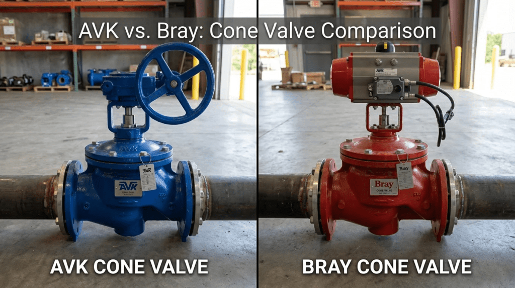
In high-head hydraulic applications and critical pump control scenarios, the margin for error is effectively zero. A single cavitation event or a failure to dissipate energy correctly can lead to catastrophic structural damage, ruptured penstocks, or destroyed downstream assets. Engineers are often faced with a distinct choice between legacy robustness and modern control versatility. This brings us to the critical evaluation of AVK vs Bray Cone Valves Equipment: Comparison & Best Fit. While AVK (often through its Glenfield or Premier legacy lines) is synonymous with traditional fixed cone (Howell-Bunger) and submerged discharge valves, Bray represents the high-performance control sector, offering advanced segmented ball and butterfly technologies that increasingly compete in the same hydraulic envelopes.
The “Cone Valve” category is niche but vital. It is primarily used in municipal dams, reservoir outlets, and wastewater treatment plant bypasses where high pressure drops must be managed without destroying the valve or the piping. A surprising statistic in hydraulic engineering is that over 40% of valve failures in high-velocity discharge applications are due to improper type selection—specifically, using a standard isolation valve for throttling duties it was never designed to handle.
Proper selection matters because the lifecycle cost of a misapplied valve in these severe service applications can exceed 500% of the initial CAPEX due to downtime, cavitation repairs, and civil structure damage. This article guides municipal and industrial engineers through the technical nuances of selecting between these two dominant manufacturing philosophies, defining where the traditional cone valve is mandatory and where modern control alternatives may offer a better fit.
How to Select / Specify
Selecting the correct equipment requires a deep dive into the hydraulic profile of the system. When analyzing AVK vs Bray Cone Valves Equipment: Comparison & Best Fit, the decision rarely comes down to brand loyalty; it comes down to physics. The following criteria should form the basis of your specification document.
Duty Conditions & Operating Envelope
The operating envelope for cone valves and their alternatives is defined by the severity of the pressure drop. Engineers must calculate the Cavitation Index (Sigma) for the entire range of valve travel.
- Fixed Cone Valves (AVK style): These are designed for free discharge into the atmosphere or submerged discharge into a stilling well. They excel where the pressure differential (Delta P) is massive, often exceeding 100 psi, and where the primary goal is energy dissipation via aeration.
- High-Performance Control Valves (Bray style): If the application involves inline throttling with moderate pressure drops, a segmented V-ball or high-performance butterfly valve (HPBV) might be specified. However, these have tighter cavitation limits compared to a sleeve-type cone valve.
- Flow Turndown: Cone valves typically offer linear flow characteristics and a high turndown ratio (often 50:1). Check if the application requires precise control at 5-10% open positions, a zone where standard valves often suffer from wire drawing.
Materials & Compatibility
Given the high velocities involved (often exceeding 35 ft/s at the discharge point), material hardness is non-negotiable.
- Sleeve/Obturator Material: For AVK cone valves, the sliding sleeve is typically Stainless Steel (304 or 316) to resist galling and erosion. For Bray control alternatives, the disc or ball segment must be hardened (e.g., Chrome carbide coating or Stellite overlays) to survive abrasive slurry or grit in wastewater.
- Body Construction: Cast ductile iron is standard for municipal water. However, for high-pressure industrial wastewater, fabricated steel bodies may be required to meet ASME B16.34 pressure classes.
- Galvanic Corrosion: In submerged discharge applications, the interface between the stainless steel sleeve and the ductile iron body is a prime location for galvanic attack. Specifications must include isolation kits or sacrificial anodes.
Hydraulics & Process Performance
The discharge coefficient (Cd) varies significantly between designs.
- Head Loss: Fixed cone valves have a relatively high Cd when fully open, providing efficient discharge. However, they create a hollow jet spray pattern which aids in oxygenation—a benefit for river discharge but a potential nuisance if spray containment is poor.
- Vibration: Comparing AVK vs Bray Cone Valves Equipment: Comparison & Best Fit requires analyzing vibration modes. Cone valves (sleeve type) are generally radially balanced, neutralizing hydraulic forces and minimizing vibration. Rotary control valves (butterfly/ball) are subject to dynamic torque and aerodynamic noise, which can cause pipe fatigue if not properly supported.
Installation Environment & Constructability
Space claims differ radically between these technologies.
- Footprint: A traditional AVK Howell-Bunger valve is long and requires a massive thrust block or hood to contain the spray. It is typically installed at the end of a line.
- Access: Bray high-performance valves are generally wafer or lug style, fitting between flanges with a minimal face-to-face dimension. This makes them ideal for retrofitting inside existing valve vaults where space is at a premium.
- Actuation: Cone valves often require twin-screw actuators to move the heavy sleeve, necessitating significant clearance for the mechanism. Rotary valves require simpler quarter-turn actuators (pneumatic, electric, or hydraulic) which are more compact.
Reliability, Redundancy & Failure Modes
Reliability in discharge valves is measured by the ability to operate after long periods of dormancy.
- Seizure: The primary failure mode for sleeve-type cone valves is scale buildup or biological growth (mussels) between the sleeve and body, causing the valve to seize. AVK designs often include flushing ports or scrapers.
- Seal Failure: For Bray rotary valves, the seat is the weak point. In throttling service, the seat can erode, leading to leakage. However, metal-seated Triple Offset Butterfly Valves (TOBV) mitigate this risk significantly.
- MTBF: Cone valves generally have a longer structural life (30-50 years) but higher maintenance requirements for the actuation screws. Rotary valves may have a shorter wear life (15-20 years) but are cheaper and faster to replace.
Lifecycle Cost Drivers
The CAPEX difference can be substantial.
- Initial Cost: A dedicated AVK Cone Valve can cost 3-5 times more than a Bray High-Performance Butterfly Valve of the same diameter.
- OPEX: The calculation must account for civil works. A cone valve often requires a concrete stilling basin or steel hood. If these structures do not already exist, the total installed cost of the cone valve solution skyrockets.
- Energy: If the valve is used for flow control in a pumped system, the head loss across the valve represents wasted energy. Select the valve with the lowest head loss at the normal operating point, not just fully open.
Comparison Tables
The following tables provide a direct side-by-side analysis to assist engineers in determining the AVK vs Bray Cone Valves Equipment: Comparison & Best Fit. Table 1 focuses on the technology differences between the traditional cone valve approach and the modern control valve alternative. Table 2 outlines the best-fit applications.
| Feature / Characteristic | AVK (Fixed Cone / Sleeve Valve) | Bray (High-Performance / Segmented Ball) | Comparison Note |
|---|---|---|---|
| Primary Mechanism | Axial movement of an external sliding sleeve over a fixed cone. | Rotary movement of a disc (Butterfly) or segmented ball (V-Ball). | AVK is “Axial”; Bray is “Rotary”. |
| Flow Characteristic | Linear; excellent throttling from 10% to 100%. | Modified Equal Percentage (V-Ball) or Linear-ish (Tri-Lok). | Cone valves offer finer resolution at low flow. |
| Energy Dissipation | Excellent. Discharges as a hollow cone spray or submerged jet. | Moderate to Good. Requires hardened trim or diffusers for high drops. | AVK is superior for “Free Discharge” into air. |
| Head Loss (Fully Open) | Moderate (Cd ~ 0.85). The cone remains in the flow path. | Very Low (V-Ball) to Low (HP Butterfly). | Bray alternatives offer better flow capacity (Cv) per inch. |
| Sealing / Shutoff | Metal-to-Metal (Class III/IV) or Soft Seated options. | Zero Leakage (Bubble Tight) often available. | Bray generally offers tighter shutoff for isolation duties. |
| Typical Size Range | 6″ to 108″+ (Custom Engineered). | 1″ to 120″ (Standard Industrial Production). | Both cover the municipal range; AVK dominates mega-projects. |
| Application Scenario | Best Fit Technology | Engineering Rationale |
|---|---|---|
| Reservoir Level Control (Free Discharge) | AVK Fixed Cone Valve | Need to oxygenate water and dissipate massive energy without damaging pipe walls. Spray containment is handled by the dam structure. |
| Pump Discharge Control (Check + Isolation) | Bray Check + HP Butterfly | While Rotary Cone valves exist, modern designs prefer a dedicated Check Valve plus a High-Performance Butterfly (Bray) for isolation to save cost and space. |
| WWTP Aeration Basin Flow Control | Bray HP Butterfly / V-Ball | Low pressure drop, need for precise air/water modulation. A heavy cone valve is overkill and too expensive here. |
| Turbine Bypass / Relief | AVK Cone Valve / Plunger Valve | Critical safety relief requiring 100% reliability under extreme velocity. Cavitation resistance is the primary driver. |
| Submerged Outfall | AVK Submerged Cone | Designed specifically to mix the discharge jet with surrounding water to reduce velocity quickly underwater. |
Engineer & Operator Field Notes
Real-world experience often diverges from the datasheet. The following insights regarding AVK vs Bray Cone Valves Equipment: Comparison & Best Fit are drawn from commissioning reports and long-term maintenance logs.
Commissioning & Acceptance Testing
Commissioning a large discharge valve is a high-stress event.
- Vibration Baseline: During Site Acceptance Testing (SAT), engineers must establish a vibration baseline across the full stroke (10%, 25%, 50%, 75%, 100%). Cone valves often exhibit a specific “singing” frequency due to vortex shedding at certain openings. This is normal unless it exceeds velocity amplitudes of 0.15 in/sec.
- Actuator Synchronization: For AVK cone valves with twin lead screws, synchronization is critical. If one screw leads the other, the sleeve jams (racking). Verify the mechanical or electrical synchronization during the FAT (Factory Acceptance Test).
- Spray Containment Verification: For free discharge valves, verify that the spray hood (if equipped) effectively directs the plume. Wind conditions during commissioning can reveal design flaws in the containment structure.
Common Specification Mistakes
- Ignoring Venting: When installing a cone valve in a submerged application or within a pipe (inline), failing to provide adequate air venting downstream will cause vacuum collapse of the pipe or severe cavitation. The valve needs to “breathe” to break the vacuum created by the high-velocity jet.
- Over-Sizing: Engineers often size control valves to match the line size. A 24″ pipe does not automatically need a 24″ control valve. Cone valves and V-balls are often sized 1-2 sizes smaller than the line to shift the control range to 30-70% open, improving resolution.
- Material Mismatch: Specifying 304SS sleeves for wastewater with high chloride content. 316SS or Duplex Stainless Steel should be the minimum standard for the sliding components to prevent pitting corrosion which destroys the seal.
O&M Burden & Strategy
Operational strategies differ between the heavy hydraulic design of AVK and the industrial design of Bray.
- Lubrication: AVK cone valves have exposed drive screws. These require monthly cleaning and greasing. In coastal or corrosive environments, these screws should be enclosed or made of highly corrosion-resistant alloys.
- Exercising: Both valve types must be exercised. A cone valve left in the open position for a year may seize due to scale buildup on the fixed cone body. Best practice is a partial stroke (10% movement) quarterly.
- Seal Replacement: Replacing the seat on a large AVK cone valve is a major rigging operation, often requiring the valve to be removed from the line or the reservoir to be drained. In contrast, Bray HP butterfly valves often have field-replaceable seats that can be serviced if the line is isolated, sometimes without removing the body from the flanges.
Design Details / Calculations
To accurately determine the AVK vs Bray Cone Valves Equipment: Comparison & Best Fit, engineers must perform specific hydraulic calculations.
Sizing Logic & Methodology
Do not rely solely on Cv (Flow Coefficient). You must calculate the Sigma factor for cavitation.
- Determine Operating Points: Define Max Flow, Min Flow, Max Head, and Min Head.
- Calculate Sigma (σ):
σ = (P_downstream - P_vapor) / (P_upstream - P_downstream)
Where P is pressure in absolute units. - Compare against Limits:
- Standard Butterfly Valve: Cavitation starts at σ < 2.5
- Bray HP Butterfly / V-Ball: Can handle σ down to ~1.5 (design dependent).
- AVK Cone Valve (Free Discharge): Can handle σ approaching 1.0 (since it discharges to atmosphere).
- AVK Cone Valve (Inline/Submerged): Designed with hood or air admission to handle σ < 1.0 effectively.
- Velocity Check: Ensure inlet velocity does not exceed manufacturer ratings (typically 20-30 ft/s for prolonged life).
Standards & Compliance
Ensure your specification references the correct standards:
- AWWA C507: Ball Valves, 6 In. Through 60 In. (Relevant for rotary cone and ball designs).
- AWWA C504: Rubber-Seated Butterfly Valves (Relevant if comparing against standard butterfly, though HPBV follows API 609 often).
- NSF/ANSI 61: Mandatory for all components in contact with potable water.
- ASME B16.34: Valves – Flanged, Threaded, and Welding End. Essential for industrial pressure ratings (Class 150, 300).
FAQ Section
What is the primary difference between a Fixed Cone Valve and a Butterfly Valve?
The primary difference is the flow geometry and energy dissipation. A Fixed Cone Valve (like those from AVK/Glenfield) uses an external sliding sleeve to create a hollow conical jet, which maximizes surface area for aeration and energy dissipation, making it ideal for high-pressure discharge. A Butterfly Valve uses a rotating disc in the flow path; while cheaper and more compact, it is prone to cavitation and noise at high pressure drops and is better suited for isolation or low-differential control.
When should I specify an AVK Cone Valve over a Bray Segmented Ball Valve?
Specify the AVK Cone Valve when you have “Free Discharge” applications (end of pipe) or extremely high pressure drops where you need to dissipate energy into a stilling basin. Specify the Bray Segmented Ball Valve (V-Ball) for “Inline” control applications where you need precise flow modulation, high rangeability (turndown), and tighter shutoff within a piping system, provided the cavitation index allows it.
How do maintenance costs compare between AVK and Bray solutions?
AVK Cone Valves have a higher initial capital cost but are built for a 50-year structural life; however, their external actuation mechanisms require regular lubrication and cleaning. Bray valves generally have lower upfront costs and lower routine maintenance (sealed gearboxes/actuators) but may require more frequent seat or trim replacements (every 10-15 years) in severe service. The “Total Cost of Ownership” depends heavily on the abrasiveness of the fluid and the frequency of operation.
What is the typical lead time for these valves?
Standard Bray High-Performance valves (up to 24″) are often stocked or assembled regionally, with lead times of 4-12 weeks. Large AVK Cone Valves are almost exclusively “Engineered to Order” (ETO), requiring casting, machining, and testing specific to the project, with typical lead times ranging from 24 to 50 weeks depending on size and foundry capacity.
Can a Cone Valve be used for tight shutoff isolation?
Historically, Cone Valves were not designed for drop-tight shutoff (Class III or IV leakage). However, modern AVK designs with resilient seats can achieve decent shutoff. Nevertheless, best engineering practice for municipal water often dictates installing a dedicated isolation valve (like a Butterfly or Gate valve) upstream of the Cone Valve to allow for maintenance and guaranteed isolation.
Why is “venting” critical for inline Cone Valve installations?
When a Cone Valve discharges into a pipe (rather than air), the high-velocity jet creates a massive low-pressure zone immediately downstream. Without adequate air admission (vent pipes), this vacuum can cause the downstream pipe to collapse inwards or induce severe cavitation that eats through the pipe wall. Proper venting restores pressure balance.
Conclusion
Key Takeaways for Engineers
- Cavitation is the Limit: Calculate the Sigma factor. If discharging to atmosphere with high head, the AVK Cone Valve is the safest choice. If inline with moderate drop, Bray Control Valves are cost-effective.
- Don’t Oversize: Control valves perform best when sized for the process conditions, not the pipe diameter.
- Venting is Mandatory: For inline or submerged cone valves, air admission is not an option—it is a requirement for pipe survival.
- Material Matters: Specify Stainless Steel sleeves/trim. Ductile iron alone will not survive the velocities seen in these applications.
- Total Cost: Account for the civil structures (stilling basins, hoods) required for Cone Valves when comparing costs against inline rotary valves.
In the analysis of AVK vs Bray Cone Valves Equipment: Comparison & Best Fit, the conclusion is rarely a declaration of one manufacturer being “better” than the other, but rather which technology fits the hydraulic physics of the site. AVK (Glenfield) remains the standard-bearer for heavy civil hydraulic engineering—dams, reservoirs, and massive energy dissipation projects where the valve is a structural component of the facility.
Bray, conversely, offers the agility of the industrial sector. Their high-performance butterfly and segmented ball valves provide municipal engineers with robust, space-saving alternatives for pump control, aeration basins, and inline throttling duties where the massive scale of a Howell-Bunger valve is unnecessary. The prudent engineer will specify the AVK style for the “End of Line” high-energy release and the Bray style for the “In-Plant” process control, ensuring that capital budget is spent where it yields the highest reliability.