
Butterfly Valves Automation: Actuation Options
Introduction
In municipal water and industrial wastewater treatment, the failure of a large-diameter isolation valve to close during a pipe burst, or the inability of a filter effluent valve to modulate flow accurately, can result in catastrophic flooding, permit violations, and massive financial losses. Yet, during the specification phase, the interface between the valve and its operator is frequently treated as an afterthought. Engineers often specify the valve body in excruciating detail—dictating disc materials and seat compounds—while leaving the Butterfly Valves Automation: Actuation Options to generic “or equal” clauses that invite under-powered or incompatible equipment.
Industry data suggests that nearly 60% of valve failures in automated systems are not due to the valve body itself, but rather the actuator sizing, the linkage, or the control interface. The butterfly valve (BFV) is ubiquitous in treatment plants due to its compact footprint and cost-effectiveness in large sizes. However, its non-linear torque characteristics and susceptibility to dynamic flow forces make automation complex. This article provides engineers and plant directors with a technical deep-dive into selecting, specifying, and maintaining automated butterfly valve assemblies, ensuring process stability and long-term reliability.
Automation is one branch of a wider subject. The general characteristics, advantages, and limitations of butterfly valves govern where the valve type is appropriate at all, and that question should be settled before the actuation question is opened. A butterfly valve correctly applied and badly actuated is a maintenance problem; a butterfly valve wrongly applied is a process problem that no actuator will fix.
From filter galleries to high-service pump stations, the correct matching of actuator capabilities to valve requirements is the difference between a “set-it-and-forget-it” asset and a perpetual maintenance headache. We will explore the engineering physics behind torque demands, compare electric and pneumatic technologies, and analyze the total lifecycle costs associated with different actuation strategies.
Subcategory Overview
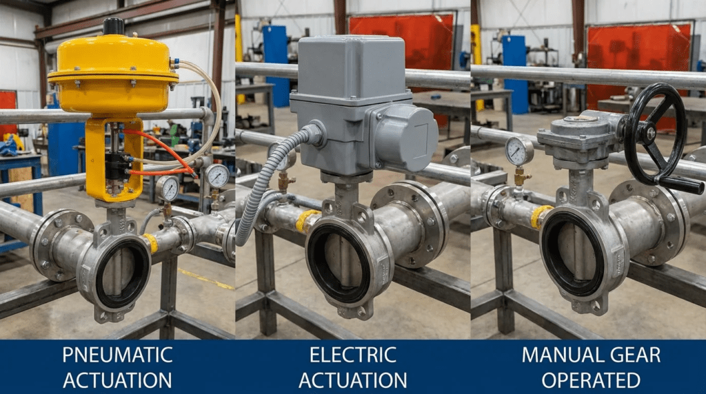
Butterfly valve actuation divides by the power source driving the operator, and the choice determines cost structure, failure behavior, control precision, and maintenance burden for the life of the installation. The subsections below outline each technology and when it becomes the governing choice.
Pneumatic Butterfly Valves
Coverage of pneumatic butterfly valves addresses the actuation family that uses compressed air acting on a piston or diaphragm, converted to quarter-turn motion through a rack-and-pinion or scotch-yoke mechanism. Two characteristics define its niche. The first is speed: pneumatic actuators stroke in seconds rather than the tens of seconds an electric gearbox requires, which matters in backwash sequencing and any application where a valve must respond to an upset rather than to a setpoint. The second is fail-safe behavior, which a spring return provides mechanically and reliably, with no battery, capacitor, or stored-energy module to maintain. That combination makes pneumatic actuation the default for emergency isolation, chemical feed shutoff, and any valve whose safe state on loss of power is something other than where it happens to be. The costs are systemic rather than per-valve: an instrument air system with compressors, dryers, receivers, and distribution piping must exist and be maintained, and air quality problems appear as valve control problems long before anyone suspects the dryer.
Electric Butterfly Valves
Coverage of electric butterfly valves addresses motor-driven actuation through a self-locking worm or spur gear train, which is the dominant choice in municipal treatment. The self-locking gearbox holds position without applied power and resists the dynamic torque that would otherwise drive the disc closed, and the motor and gear combination delivers precise, repeatable positioning suitable for continuous modulation. Modern units are effectively field instruments: they report position, torque profile, motor temperature, and cycle count over a digital protocol, and many can close a control loop locally rather than loading the central PLC. The trade-offs are a higher unit price, a power supply requirement at every valve location, and fail-safe behavior that must be engineered rather than being inherent. This area also covers the duty cycle question, which is where electric actuator specifications most often go wrong.
Other Actuation Methods
Two further options sit outside the current subtopic coverage but belong in any complete evaluation. Manual gear operators with a handwheel or chainwheel remain the most common arrangement on small and mid-size butterfly valves and are the correct answer wherever the valve is operated rarely and an operator can reach it; automating such a valve adds cost and a failure mode without adding capability. Electro-hydraulic actuation occupies the opposite extreme, delivering very high torque in a compact package for large-diameter valves that exceed what electric or pneumatic units can move, at the cost of a power unit, fluid management, and leak risk. Both are covered in the comparison tables below, though neither currently has a dedicated subtopic page.
How to Select / Specify
Selecting the correct automation package requires a holistic view of the process conditions. Engineers must move beyond simple “open/close” logic and evaluate the dynamic behavior of the fluid and the mechanical response of the valve assembly. The following criteria define the specification framework for Butterfly Valves Automation: Actuation Options.
Duty Conditions & Operating Envelope
The operating envelope dictates the fundamental class of actuator required. Engineers must clearly define the frequency of operation and the precision required.
- Isolation (On/Off) Duty: Valves that operate infrequently (e.g., pump isolation, tank drain). The actuator must be rated for “short-time duty” (S2 rating in IEC standards), typically capable of running for 15 minutes continuously before requiring a cooling period.
- Modulating (Control) Duty: Valves used for flow or pressure regulation (e.g., aeration control, filter effluent). These require Class III or IV actuators capable of continuous modulation (S4 rating), handling up to 1,200 starts per hour without overheating.
- Inching/Positioning: A middle ground where valves are adjusted periodically to set points but do not hunt continuously.
Pressure Differential (ΔP): The maximum shut-off pressure determines the seating torque. However, for modulating valves, the engineer must also calculate the dynamic torque at various opening angles (typically peaking between 60° and 75° open) to ensure the actuator does not stall mid-travel.
Materials & Compatibility
The actuator enclosure and mounting hardware must survive the plant environment. Standard aluminum enclosures are often insufficient for corrosive atmospheres found in wastewater headworks or chemical feed rooms.
- Enclosure Ratings: NEMA 4X (IP66) is the baseline for outdoor or washdown areas. For submersion risks (e.g., valve vaults), specify NEMA 6P (IP68), which typically requires double-sealing technology to protect internal electronics even if the terminal compartment is opened during a flood.
- Corrosion Protection: In hydrogen sulfide (H2S) rich environments, specify epoxy-coated ductile iron or 316 stainless steel enclosures.
- Mounting Kits: The bracket and coupling connecting the actuator to the valve stem are critical weak points. Specify stainless steel mounting hardware to prevent corrosion from seizing the assembly, making future maintenance impossible.
Hydraulics & Process Performance
Butterfly valves exhibit specific hydraulic behaviors that influence automation choices. The flow characteristic is generally equal percentage, but torque requirements change drastically throughout the stroke.
- Seating/Unseating Torque: The highest torque demand usually occurs when breaking the valve seat seal (unseating). Actuators must be sized with a safety factor (typically 1.25 to 1.5) above this breakaway torque.
- Dynamic Torque Reversal: As water flows past the disc, the airfoil shape creates lift, which can act to close the valve self-actuated. The actuator gearing must be self-locking (e.g., worm gear) to prevent the valve from slamming shut or “fluttering” under high velocity.
- Stroke Speed: Rapid closure can cause water hammer. Automation specifications must include adjustable speed controls. Electric actuators may require Variable Frequency Drives (VFDs) or DC motors to adjust speed; pneumatic actuators require flow control valves on the exhaust ports.
Seat design is the largest single variable in seating torque, and it is determined by the valve rather than the actuator. Resilient-seated concentric valves require the actuator to compress an elastomer across the full disc circumference; high-performance double-offset and triple-offset designs use a cammed action that lifts the disc clear of the seat almost immediately, substantially reducing breakaway torque at the cost of a more expensive valve. Because the two decisions are coupled, engineers should work through the butterfly valve types selection and the actuation sizing together rather than sequentially, since a change in seat design can move the torque requirement by enough to change the actuator size.
Installation Environment & Constructability
Physical constraints often dictate the choice between electric and pneumatic options.
- Space Constraints: Pneumatic scotch-yoke actuators can be bulky and require swing clearance. Electric multi-turn actuators are generally more compact vertically but may be taller.
- Power Availability: Electric actuators typically require 3-phase 480V or single-phase 120V/240V. If high voltage is unavailable at the valve vault, low-power 24VDC actuators (often limited in torque) or pneumatic systems (if instrument air is available) become necessary.
- Orientation: While many actuators can be mounted in any orientation, mounting them vertically (motor up) is preferred to prevent sediment from accumulating on the shaft seal and to ensure the oil bath lubricates the gears properly.
Vendor and Mounting Standardization
Beyond the technology decision, two commercial choices shape the maintenance burden for decades. The first is whether the actuator arrives factory-mounted and tested on the valve or is supplied loose for field mounting. Factory mounting places responsibility for the bracket, coupling, alignment, and end-stop setting with a single supplier and eliminates the most common source of startup disputes, and it is worth specifying explicitly rather than leaving to the bidder. The second is standardization across the plant. A facility running three actuator brands carries three spare parts inventories, three configuration tools, and three sets of training. Evaluating the butterfly valve manufacturers and their actuator partnerships together, rather than bidding valves and actuators separately, generally produces a more maintainable result even where it costs marginally more at purchase. ISO 5211 mounting flanges make substitution mechanically possible, but mechanical interchangeability does not extend to controls, configuration, or diagnostics.
Reliability, Redundancy & Failure Modes
Defining the “Fail-Safe” condition is a critical specification step. What happens when power is lost?
- Fail-Last (Fail-in-Place): Standard for electric actuators with self-locking gears. The valve stays where it is.
- Fail-Open/Close: Critical for fire protection or storm management.
- Pneumatic: Easily achieved with a spring-return mechanism. Highly reliable.
- Electric: Requires an internal battery backup, supercapacitors, or a spring-return module (which significantly increases cost and size).
- Manual Override: All automated valves must have a declutchable manual handwheel for emergency operation. Specify that the handwheel must not rotate during automatic operation to protect operators.
Controls & Automation Interfaces
Modern plants are moving away from hardwired I/O toward digital networks.
- Discrete/Analog (Hardwired): Uses dry contacts for Open/Close/Fault status and 4-20mA signals for position. Simple, easy to troubleshoot, but requires massive amounts of cabling.
- Fieldbus (Digital): Protocols like Modbus, Profibus, or Ethernet/IP allow the actuator to transmit rich data: torque profiles, motor temperature, vibration alerts, and cycle counts. This enables predictive maintenance but requires specialized integration skills.
- Intelligent Actuators: Modern electric actuators contain onboard logic. They can perform PID control locally, taking a direct process variable input (e.g., from a flow meter) and adjusting position without loading the central PLC.
Maintainability, Safety & Access
Butterfly Valves Automation: Actuation Options must consider the human element.
- Lockout/Tagout (LOTO): Actuators should have integral padlocking provisions on the local selector switch.
- Separation of Controls: For valves in hazardous locations (Class 1 Div 1), specify remote-mounted control heads so operators can interact with the keypad/display from a safe area, while the motor/gearbox remains in the hazard zone.
- Lubrication: Specify “sealed for life” gearboxes where possible to reduce PM requirements. If oil-filled, ensure drain and fill ports are accessible.
Lifecycle Cost Drivers
The total cost of ownership (TCO) varies significantly between technologies.
- Electric Actuation: Higher initial CAPEX per unit. Low installation cost (just power and control cables). Very low maintenance (check oil, check seals). High energy efficiency (consumes power only when moving).
- Pneumatic Actuation: Lower CAPEX per unit (for small/medium sizes). High installation cost (requires compressors, dryers, air loop piping). High OPEX (compressed air leaks are expensive; air generation is energy-intensive). Maintenance intensive (filter regulators, dryers, solenoid replacements).
Comparison Tables
The following tables provide a structured comparison to assist engineers in narrowing down the Butterfly Valves Automation: Actuation Options. Table 1 compares the fundamental actuation technologies, while Table 2 provides an application-specific selection matrix.
| Technology Type | Primary Features | Best-Fit Applications | Limitations & Considerations | Maintenance Profile |
|---|---|---|---|---|
| Electric (Multi-turn / Quarter-turn) |
|
|
|
Low: Periodic inspection of seals and desiccant. Gearbox oil change every 5-10 years. Electronics are the primary failure point. |
| Pneumatic (Rack & Pinion / Scotch Yoke) |
|
|
|
High: Air compressor and dryer maintenance. Solenoid valve replacement. Seal kits for cylinders. Leak detection is constant. |
| Electro-Hydraulic |
|
|
|
Medium-High: Fluid level checks, filter changes, accumulator charge checks. Seal degradation over time. |
| Application Scenario | Valve Duty | Fail-Safe Need | Key Constraint | Recommended Solution |
|---|---|---|---|---|
| Filter Effluent Control | Modulating (Continuous) | Fail-Last or Close | Precision flow control to prevent turbidity spikes. | Electric Modulating (Class III/IV). High resolution avoids “hunting.” |
| Aeration Basin Air Flow | Modulating (Continuous) | Fail-Last | High temperature, vibration, continuous adjustment. | Electric with Remote Mount Head. Separates electronics from vibration/heat. |
| Raw Sewage Pump Isolation | Isolation (Open/Close) | Fail-Last | Reliability in corrosive H2S environment. | Electric (NEMA 6P) or Pneumatic if air available. Emphasis on corrosion resistance. |
| Chlorine/Chemical Feed | Isolation/Modulating | Fail-Close (Safety) | Chemical compatibility and immediate shutoff. | Pneumatic with Spring Return. Simplest, most reliable safety trip. |
| Emergency High-Level Overflow | Isolation (Rare) | Fail-Open | Must operate after months of dormancy without power. | Pneumatic Spring-Return or Hydraulic w/ Accumulator. |
Engineer & Operator Field Notes
Successful implementation of Butterfly Valves Automation: Actuation Options relies on execution in the field. The following notes are compiled from commissioning reports and operator logs.
Commissioning & Acceptance Testing
The Factory Acceptance Test (FAT) verifies the equipment works on the bench, but the Site Acceptance Test (SAT) proves it works under load.
- End Stop Setting: A common mistake is setting the electronic limits exactly at the mechanical stops. This causes the actuator to torque-out against the physical stop, damaging the gearing. Set electronic limits 2-3 degrees off the mechanical stop.
- Torque Switch Calibration: Never set the torque switch to “Maximum” or “Bypass” to overcome a sticky valve. This removes the safety protection for the valve stem. If the valve won’t move at the rated torque, there is a mechanical obstruction or sizing error.
- Phasing Check: For 3-phase electric actuators, bumping the motor to check rotation direction is critical. Incorrect phasing can cause the actuator to drive into the closed seat while thinking it is opening, leading to catastrophic stem failure. Modern smart actuators often have auto-phase correction.
- Baseline Torque Profile: Capture and archive the full open and close torque profile at commissioning while the valve, seat, bearings, and packing are new. Every later diagnosis of a binding or leaking valve depends on having that reference, and it cannot be recreated once the valve has been in service.
Common Specification Mistake: Sizing by Line Size. Do not assume a 12-inch actuator fits a 12-inch valve. A 12-inch valve at 50 psi requires significantly less torque than a 12-inch valve at 150 psi. Always provide the maximum differential pressure (ΔP) and flow velocity to the actuator manufacturer.
O&M Burden & Strategy
Maintenance strategies differ vastly based on the actuation method selected.
- Desiccant Packs (Electric): The most common failure in electric actuators is moisture ingress. Operators must check the desiccant pack inside the terminal compartment annually. If it turns pink (wet), replace it and inspect door seals.
- Air Quality (Pneumatic): Pneumatic positioners are notoriously sensitive to oil and water in the air lines. If the plant air dryer fails, pneumatic positioners will foul quickly, leading to erratic valve control. A point-of-use filter regulator is mandatory for every pneumatic valve.
- Partial Stroke Testing: For emergency valves that rarely operate, implement a “Partial Stroke Test” (PST) logic in the SCADA system. This moves the valve 10% and back every month to ensure it hasn’t seized, without disrupting the process.
Troubleshooting Guide
- Symptom: Valve Hunting (Oscillating). The valve constantly opens and closes slightly. Root Cause: Deadband is too tight, or the PID loop is too aggressive. Fix: Widen the actuator deadband (e.g., from 0.5% to 1.0%) or detune the PLC PID loop.
- Symptom: Torque Fault at Mid-Travel. Actuator stops and alarms “Torque Trip” while opening. Root Cause: Debris accumulation, bearing seizure, or dynamic torque caused by high velocity flow. Fix: Check for “dynamic torque reversal.” If flow velocity is >16 ft/s, the hydrodynamic forces may exceed the actuator rating.
- Symptom: Breakaway Torque Climbing Over Successive Operations. The actuator takes progressively more torque to unseat the valve. Root Cause: Seat compression set, scale accumulation on the disc edge, or bearing wear pulling the shaft out of alignment. Fix: Compare against the commissioning baseline to gauge severity and schedule service before the trend reaches the actuator’s torque limit.
Pro Tip: Heater Power. All electric actuators and pneumatic positioners used outdoors must have internal anti-condensation heaters. Ensure the electrical design provides a constant power source for these heaters, even when the motor is not running. Without heaters, condensation will form overnight and corrode internal contacts within months.
Design Details / Calculations
To accurately specify Butterfly Valves Automation: Actuation Options, engineers must understand the underlying physics of valve torque.
Sizing Logic & Methodology
The total torque required to operate a butterfly valve is the sum of several components. Actuators should be sized to exceed that total by a safety margin.
- Seating Torque (Tseat): The friction required to displace the rubber seat or crush the metal seal. This is a function of valve diameter and shut-off pressure, and it dominates at 0° open.
- Bearing Friction Torque (Tbearing): Friction in the shaft bearings, approximately equal to pressure multiplied by shaft area multiplied by the friction coefficient.
- Packing Friction (Tpacking): Constant friction from the gland seal. Usually minimal but non-zero.
- Dynamic Torque (Tdynamic): The hydrodynamic force of fluid acting on the disc wing. For symmetric discs this torque tends to close the valve, and it typically peaks between 60° and 75° of travel.
Safety Factor Application:
- General Service: Use 1.25 safety factor.
- Modulating Service: Use 1.5 safety factor to account for wear and frequent movement.
- Corrosive/Sludge Service: Use 2.0 safety factor to account for scale buildup increasing friction over time.
Worked Sizing Example
Consider a 24-inch rubber-seated butterfly valve in filter effluent service at 100 psi maximum differential pressure, operating in modulating duty. Using illustrative figures of the kind a manufacturer’s torque table would supply, the components might fall out as follows: seating torque of roughly 6,000 inch-pounds, bearing friction of 1,500, packing friction of 200, and a dynamic torque peak near 70 degrees of about 2,500.
Two operating points then have to be checked rather than one. At breakaway, the demand is seating plus bearing plus packing, roughly 7,700 inch-pounds. At the dynamic peak, the disc is already off the seat, so the demand is bearing plus packing plus dynamic, roughly 4,200 inch-pounds. Breakaway governs here, and applying the 1.5 modulating safety factor gives a required actuator output near 11,550 inch-pounds, or about 960 foot-pounds.
The point of working it through both ways is that breakaway does not always govern. On a large valve in high-velocity service, the dynamic peak can exceed the seating torque, and an actuator sized only on the breakaway figure will stall mid-stroke. This is why the specification should require the manufacturer to submit the actuator output curve overlaid on the valve torque demand curve across the full travel rather than a single number.
Specification Checklist
When writing the Division 40 or 15 specifications, ensure these critical items are included:
- Duty Cycle: Explicitly state S2 (Short time) or S4 (Continuous modulating) per IEC 60034-1.
- Speed of Operation: Define “Time to Close” (e.g., 60 seconds). Too fast means water hammer; too slow means overflow.
- Signal Loss Mode: Define what the valve must do on loss of 4-20mA signal (Hold Last, Go Open, Go Close).
- Communication Protocol: Modbus TCP, Ethernet/IP, Profibus DP, or Hardwired.
- Documentation: Require torque sizing calculations from the valve manufacturer showing the actuator torque output overlaid on the valve torque demand curve.
- Mounting Responsibility: State whether the actuator is factory-mounted and tested on the valve or supplied loose, and name the party responsible for bracket, coupling, alignment, and end-stop setting.
- Baseline Data: Require the commissioning contractor to deliver the open and close torque profile as a closeout document.
Standards & Compliance
- AWWA C504: Standard for Rubber-Seated Butterfly Valves. Defines proof-of-design tests.
- AWWA C542: Standard for Electric Motor Actuators for Valves and Slide Gates.
- AWWA C541: Standard for Hydraulic and Pneumatic Cylinder and Vane-Type Actuators for Valves and Slide Gates.
- NEMA 250 / UL 50: Enclosure ratings (Type 4X, 6P).
- ISO 5211: Standard for part-turn actuator attachments (mounting flanges).
- IEC 60034-1: Rotating electrical machines, defining the S1 through S9 duty cycle classifications referenced above.
Frequently Asked Questions
What is the difference between S2 and S4 duty cycles in electric actuators?
Duty cycles define the thermal limits of the motor. S2 (Short-Time Duty) is for isolation valves that operate infrequently; the motor can run for a short duration (e.g., 15 minutes) but must cool down to ambient temperature before restarting. S4 (Intermittent Periodic Duty) is for modulating valves; it allows for frequent starts (up to 1,200/hour) and jogging without overheating. Specifying an S2 actuator for a modulating control loop will lead to motor burnout.
Why is “dynamic torque” critical for Butterfly Valves Automation: Actuation Options?
Dynamic torque is the force exerted by the fluid flow on the valve disc. In butterfly valves, the flow creates a lifting force similar to an airplane wing, which tries to close the valve. This force usually peaks when the valve is 60-70 degrees open. If the actuator is sized only for the seating torque (0 degrees), the dynamic torque at high flow rates might overpower the actuator mid-stroke, causing the valve to slam shut or stall.
How do I choose between electric and pneumatic actuation for wastewater applications?
Choose electric when you need precise modulation, data integration (SCADA), or when the distance from an air source is large. Electric is generally preferred for filter galleries and remote pump stations. Choose pneumatic for hazardous areas (explosion-proof requirements), fast-acting safety valves, or wet environments where electrics might fail. Pneumatic systems have lower unit costs but higher long-term maintenance costs due to air system upkeep.
What is the recommended safety factor for sizing valve actuators?
A safety factor of 1.25 is the industry minimum for clean water. However, for wastewater or sludge applications where debris or grease can increase friction, a safety factor of 1.5 to 2.0 is recommended. Furthermore, always size the actuator based on the lowest available supply voltage (e.g., 90% of nominal) and the lowest available air pressure (e.g., 60 psi instead of 80 psi).
Can I retrofit an automated actuator onto an existing manual butterfly valve?
Yes, but it requires careful engineering. You must verify the ISO 5211 mounting pad dimensions and the stem diameter/keyway. More importantly, the existing manual valve may be old and have increased internal friction; torque testing the valve with a torque wrench before ordering the actuator is highly recommended. Also, check that the valve stem is robust enough to handle the motorized torque, which is applied much faster than manual operation.
What prevents water hammer during automated valve closure?
Water hammer is caused by rapid changes in fluid velocity. To prevent it, the actuator closure speed must be controlled. For electric actuators, this means selecting a gear ratio that provides a slow closure time (e.g., 60-120 seconds) or using a variable speed drive. For pneumatic actuators, speed control valves (needle valves) must be installed on the exhaust ports to restrict air release and slow the stroke. The closure profile is critical; the last 10% of closure creates the most significant pressure spike.
When should a butterfly valve stay manually operated?
Whenever the valve is operated rarely, an operator can physically reach it, and no interlock or remote control requirement exists. Automating a valve that is cycled twice a year adds a motor, a gearbox, a power feed, a control interface, and a set of failure modes in exchange for convenience that nobody uses. A manual gear operator with a handwheel or chainwheel, exercised on a documented schedule, is more reliable over twenty years than an actuator that sits unpowered in a vault. Reserve automation for valves that genuinely need remote operation, frequent cycling, precise positioning, or a defined fail position.
Conclusion
Key Takeaways
- Process Dictates Technology: Use modulating (S4) electric actuators for precise control loops; use pneumatic spring-return for critical fail-safe safety applications.
- Torque is Non-Linear: Do not size based solely on seating torque. Account for dynamic torque at 60-70 degrees open and apply a 1.25-1.5 safety factor.
- Environment Matters: Specify NEMA 6P (IP68) for valve vaults subject to flooding and heaters for all outdoor installations to prevent condensation.
- Speed Control is Mandatory: Ensure actuators can be adjusted to close slowly enough to prevent water hammer surges in the piping system.
- Total Cost of Ownership: Electric has higher CAPEX but lower OPEX. Pneumatic appears cheaper initially but carries the hidden cost of maintaining air compressors and dryers.
- Seat Design Drives Torque: Resilient-seated and offset high-performance valves impose very different breakaway demands, so valve type and actuator sizing are one decision rather than two.
- Baseline at Commissioning: Record the torque profile while everything is new; without it, every later diagnosis of a binding valve is guesswork.
Selecting the right Butterfly Valves Automation: Actuation Options is a balance of hydraulic physics, environmental constraints, and operational philosophy. The valve body and the actuator must be treated as a unified system rather than separate line items. Engineers who invest time in calculating precise torque requirements, defining clear duty cycles, and planning for failure modes will deliver systems that protect plant infrastructure and reduce the burden on operations staff.
When specifying these systems, resist the urge to copy and paste previous specifications. Review the unique flow dynamics, failure consequences, and integration requirements of the specific project. By focusing on reliability, maintenance access, and proper sizing margins, you ensure that the automated valves serve as robust assets rather than points of failure in the water treatment process.