
Evoqua vs NEFCO Systems for Clarification: Pros/Cons & Best-Fit Applications
Introduction
In the landscape of wastewater treatment, the secondary clarifier is often the ultimate bottleneck of the activated sludge process. While biological reactors receive attention for nutrient removal, the clarifier is the final gatekeeper of effluent quality. A pattern seen repeatedly in performance investigations is that a large share of clarifier problems are not caused by biological settling characteristics at all, but by hydraulic inefficiencies—density currents, short-circuiting, and poor energy dissipation. This is where the engineering decision becomes critical.
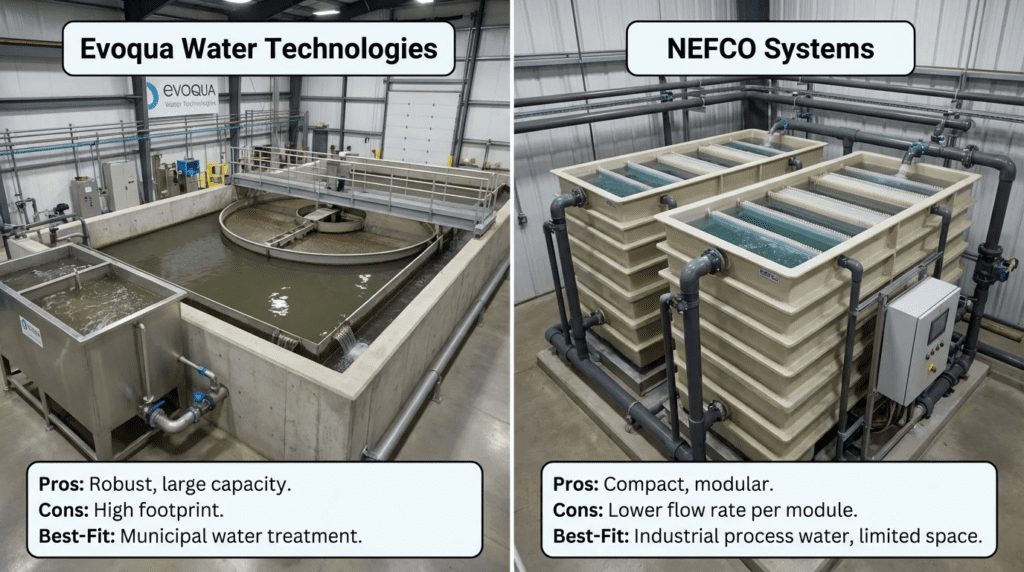
When specifying equipment for new builds or optimizing existing assets, consulting engineers frequently face a choice between integrated mechanical suppliers and specialized hydraulic optimizers. This brings us to the comparative analysis of Evoqua vs NEFCO Systems for Clarification: Pros/Cons & Best-Fit Applications. Evoqua, now part of Xylem, carries the legacy of the complete mechanism, holding the lineage of the Envirex, Rex, and Link-Belt product families. They provide the heavy iron—the rakes, drives, and suction headers. NEFCO Systems has by contrast carved a niche in hydrodynamic optimization, specializing in engineered fiberglass reinforced plastic density current baffles, launder covers, and weir accessories that fundamentally alter the hydraulic profile of the tank.
This article moves beyond the brochure to focus on the physics of sedimentation, the reality of material science, and the operational lifecycle of these systems. We examine why an engineer might pair a hydraulic suction mechanism with specialist FRP baffles, or why a utility might choose a single-source package over a best-in-class component approach. This pairing is one of several within the broader field of clarifier equipment manufacturers, and understanding the distinct engineering philosophies involved allows plant directors and design engineers to make specification-safe decisions that minimize effluent solids carryover and maximize asset longevity.
Related Clarification Equipment Comparisons
Clarifier performance depends on three things that are usually procured separately: the mechanism that moves solids, the hydraulics that determine where those solids go, and the instrumentation that tells the operator what is actually happening in the tank. The comparison in this article addresses the first two. The comparisons below address the third, plus a further mechanism-versus-mechanism pairing that recurs in municipal procurement.
Mechanism Suppliers: Evoqua and ClearStream Environmental
The comparison of Evoqua vs ClearStream Environmental for clarification is a direct mechanism-to-mechanism evaluation, in contrast to the mechanism-versus-hydraulics framing of this article. It turns on the considerations that dominate any collector comparison: drive torque rating and the basis on which it is stated, whether overload protection is electronic or mechanical, rake and squeegee design against the expected solids, structural design of the bridge or cage, and—often decisive on a retrofit—whether the supplier will adapt to an existing tank’s dimensions or requires the tank to suit the mechanism.
The practical guidance is to compare torque ratings on a common basis before anything else. Continuous rating, momentary peak rating, and the AGMA service class behind them are frequently quoted inconsistently between suppliers, and a mechanism appearing well matched on a headline figure can be substantially under-rated once the basis is normalized.
Flow and Level Instrumentation: Krohne and ABB
The Krohne vs ABB clarification equipment comparison addresses the measurement side of clarifier operation, which determines whether the mechanism and the hydraulics can be managed at all. The critical measurements are return activated sludge flow, waste activated sludge flow, and sludge blanket level, and none of them is straightforward. RAS and WAS streams are dense, variable in solids concentration, and often carry rags, which makes electromagnetic metering the practical default and makes electrode and liner selection a real decision rather than a catalog default.
Sludge blanket measurement deserves particular attention because it is the parameter operators most want and most often mistrust. Ultrasonic and optical blanket detectors each have characteristic failure modes—fouling of the sensor face, false returns from a diffuse blanket, drift as sludge characteristics change seasonally—and a blanket reading nobody trusts is functionally the same as no blanket reading at all. Specify the mounting arrangement so the sensor can be cleaned without draining the tank, and specify a verification method so the reading can be checked against a manual core sample.
Metering and Control Platforms: Badger Meter and Siemens
The Badger Meter vs Siemens clarification equipment comparison introduces a difference of scope rather than of capability. One is a focused metering specialist, the other a full automation platform vendor whose instrumentation integrates with a broader control architecture. Which fits depends on whether the clarifier instrumentation is a standalone requirement or a node within a plant-wide control strategy.
The engineering point that unites both instrumentation comparisons is that clarifier control loops are only as good as their measurements. RAS rate control based on a drifting flow meter, or blanket control based on a fouled detector, produces confident automation of the wrong action. Where a plant is investing in mechanism upgrades or hydraulic retrofits, upgrading the instrumentation that will verify the improvement is a small additional cost that makes the rest of the investment measurable.
The Wider Supplier Field
Beyond these pairings, the broader field of clarification equipment OEMs spans mechanism manufacturers, hydraulic specialists, and suppliers of complete package clarifiers for smaller plants. Establishing which of these categories the project actually needs, before comparing named suppliers within any of them, is what keeps a specification coherent.
How to Select / Specify
Selecting between or combining these technologies requires a nuanced understanding of clarifier mechanics. The specification process must separate the sludge removal mechanism from the hydraulic management system, because they solve different problems and fail in different ways.
Duty Conditions & Operating Envelope
The first step in specification is defining the hydraulic and solids loading regimes.
- Surface Overflow Rate: For clarifiers operating near peak overflow rate, commonly above 800 to 1,000 gpd per square foot, hydraulic stability is paramount. Density current baffles are specifically designed to retain solids in high-flow scenarios where the wall current would otherwise cause blanket washout.
- Solids Loading Rate: Where the plant operates with high mixed liquor concentration or high return rates, mechanical torque becomes the limiting factor. Drive units must be engineered for the resulting load, and engineers must calculate running torque and alarm torque from the worst-case solids loading rather than the design average.
- Variable Flow: Plants with large wet weather flows require rapid sludge withdrawal to prevent denitrification and rising sludge. Hydraulic suction systems offer a distinct advantage over scraper plows here, because they remove sludge across the entire tank radius simultaneously rather than transporting it to a central hopper.
Materials & Compatibility
Material of construction is a major differentiator between these two approaches.
- FRP versus Steel: NEFCO systems are almost exclusively fiberglass reinforced plastic, offering superior corrosion resistance in the aggressive headspace of a clarifier where H2S is present. Evoqua typically uses coated carbon steel or stainless for structural mechanisms including bridges and rake arms, though FRP baffles are also offered.
- UV Stability: For launder covers and exposed baffles, ultraviolet degradation is a real failure mode. Specifications must call out UV inhibitor additives in the resin matrix and appropriate surface veils to prevent fiber exposure after a decade or more of service.
- Dissimilar Metals: When retrofitting FRP baffles onto an existing steel tank or mechanism, galvanic isolation is less of a concern than in steel-to-steel connections, but fastener selection matters: 316 stainless is the practical minimum at anchor points in this environment.
Hydraulics & Process Performance
This is where the comparison becomes a discussion of fluid dynamics rather than of equipment.
- Density Current Management: Mixed liquor entering a clarifier is denser than the clarified water above. It plunges to the floor, travels outward, strikes the outer wall, and curls upward—carrying solids over the weir. Density current baffles are geometrically arranged to intercept that wall current and redirect it inward, returning the solids to the settling zone.
- Suction versus Scraping: A scraper pushes sludge spirally toward a center hopper, a transit that can take a substantial fraction of an hour in a large tank. Hydraulic suction removes sludge locally across the radius. In biological nutrient removal plants, that reduced residence time in the blanket is important because it limits secondary phosphorus release.
Installation Environment & Constructability
- Retrofit Capability: FRP baffle systems are designed for constructability in existing tanks, with modular panels and bracket systems that accommodate out-of-round concrete—a common reality in municipal infrastructure.
- Structural Loads: Adding launder covers changes the dead load and wind load profile on the tank wall or launder cantilever. Engineers must verify concrete structural capacity, particularly for snow loads in northern climates.
Reliability, Redundancy & Failure Modes
- Mechanical Failure: Mechanisms involve moving parts—gears, bearings, chains—and fail through wear or torque overload. A well-maintained center drive commonly achieves twenty years or more of service, but that depends on a real lubrication and oil analysis program rather than an assumed one.
- Static Failure: Baffle systems are largely static. Their failure modes are bracket corrosion, where an inadequate fastener grade was specified for the H2S environment, and impact damage. Reliability is inherently higher for static components, but they do not actively remove sludge.
Maintainability, Safety & Access
- Algae Control: A major driver for launder covers is reduced operating labor. Open launders require regular scrubbing to prevent algae growth that fouls weirs and degrades effluent quality; covers block sunlight and largely eliminate the task.
- Walkway Safety: Both suppliers offer access provisions. Mechanism bridges are structural supports; cover systems often provide weir access for inspection. Specifications must mandate anti-slip surfaces and compliance with the applicable OSHA guardrail and walking-working surface requirements.
Lifecycle Cost Drivers
- Energy: Drives consume continuous power. The efficiency of the worm gear or planetary reducer is a real operating cost calculation over a twenty-year life.
- Labor: Launder covers meaningfully reduce weir cleaning labor during the algae season, and where that labor is currently a recurring weekly task the payback is usually short. Quantify it from the plant’s actual cleaning hours rather than from a generic figure.
- Coating versus Replacement: Steel mechanisms require recoating on a cycle commonly cited at 15 to 20 years, a substantial expense involving blasting and containment. FRP components require no painting, which materially lowers long-term asset management cost.
Selection & Specification Framework
The criteria above are individually familiar. What produces underperforming clarifiers is applying them out of order—most commonly by specifying a mechanism, then treating hydraulics and instrumentation as accessories rather than as design decisions in their own right.
Step 1: Diagnose Before Specifying
Establish whether the problem is mechanical, hydraulic, or biological before selecting anything. Rising sludge at the outer wall with a low blanket points to hydraulics. High torque with a deep blanket points to solids inventory or the mechanism. Poor settleability at all loadings points upstream to the biological process, and no clarifier equipment will fix it. Specifying equipment against a misdiagnosis is the most expensive error available in this category.
Step 2: Establish Both Loading Rates at Peak
Clarifiers are governed by surface overflow rate at low solids and by solids loading rate at high solids, and which one controls shifts with operating conditions. Calculate both at average and at peak wet weather flow, with the return rate stated, and identify which governs in each condition.
Step 3: Worked Loading Example
Consider two 90-foot diameter secondary clarifiers serving a plant with an average flow of 6 MGD and a peak wet weather flow of 15 MGD, operating at 3,000 mg/L mixed liquor with a 60 percent return rate. Each clarifier presents roughly 6,360 square feet of surface area, for 12,720 square feet total.
At average flow, the surface overflow rate is 6,000,000 divided by 12,720, or approximately 470 gpd per square foot—comfortably conservative. At peak wet weather flow it rises to roughly 1,180 gpd per square foot, which is above the range where an unbaffled clarifier reliably retains its blanket, and precisely the condition in which density current baffles earn their cost.
The solids loading check tells a different story. Total flow to the clarifiers at peak, including 60 percent return, is 15 plus 9, or 24 MGD. Solids loading is that flow multiplied by the mixed liquor concentration and by 8.34, divided by the surface area: 24 times 3,000 times 8.34, or roughly 600,000 pounds per day, over 12,720 square feet—approximately 47 pounds per square foot per day. That is at or beyond the upper end of conventional design practice for activated sludge, which means at peak the clarifiers are solids-limited as well as hydraulically stressed. Baffles will help the hydraulic component; they will not resolve the solids loading, which requires either reducing the return rate during peak events, lowering mixed liquor concentration seasonally, or adding surface area. Running both calculations is what distinguishes a targeted fix from an expensive partial one.
Step 4: Verify the Mechanical and Hydraulic Interface
Where a static baffle system is added to a rotating mechanism, the clearance envelope between the rake arm, the skimmer arm, and the baffle brackets must be verified from field measurement before fabrication. This is the single most common design conflict in clarifier retrofits, and it is entirely avoidable at the shop drawing stage.
Step 5: Specify the Instrumentation That Will Verify the Result
A clarifier upgrade without blanket level and RAS flow measurement cannot be demonstrated to have worked. Specify the measurements, their mounting and cleaning access, and a verification method, so that the performance claim made at bid can be tested in service.
Step 6: Compare on Lifecycle Cost Including Labor
Build the comparison from installed capital, drive energy, recoating cycles with their containment and outage cost, weir and launder cleaning labor, and the process consequence of effluent solids excursions. The labor and compliance terms are usually where FRP hydraulic components justify themselves, and they sit in budgets that capital bid comparisons rarely examine.
Comparison Tables
The following tables provide a side-by-side analysis to assist engineers in distinguishing the primary competencies of each approach. Table 1 covers equipment attributes; Table 2 outlines application suitability.
| Feature/Attribute | Evoqua (Envirex and Rex legacy) | NEFCO Systems |
|---|---|---|
| Core Competency | Active mechanical sludge removal through drives, rakes, and suction headers. | Passive hydraulic optimization through baffles and weirs, plus algae control via covers. |
| Primary Materials | Coated carbon steel, stainless steel, cast iron. | Fiberglass reinforced plastic with 316 stainless hardware. |
| Characteristic Technology | Hydraulic suction headers, peripheral feed arrangements, and folded flow configurations. | Density current baffles, launder covers, and weir cleaning accessories. |
| Process Impact | Determines return sludge concentration and inventory control; critical for nutrient removal. | Reduces effluent solids by limiting short-circuiting; inhibits algae growth on weirs. |
| Installation Type | Heavy construction requiring craneage for drives and bridges, with precision leveling. | Lightweight modular assembly, frequently hand-carried into the tank. |
| Maintenance Profile | Medium to high: gearbox oil changes, torque calibration, seal replacement, structural recoating. | Low: visual inspection of brackets and anchors; occasional cleaning of covers. |
| Failure Consequence | Mechanism stoppage takes the clarifier out of service; blanket accumulates rapidly. | Degraded hydraulics reduce capacity but the clarifier continues to operate. |
| Scenario / Constraint | Mechanism Consideration | Hydraulic Consideration | Combined Approach |
|---|---|---|---|
| New nutrient removal plant | Specify hydraulic suction for rapid sludge removal to limit phosphorus release. | Specify density current baffles to maximize usable capacity. | Yes: suction mechanism plus baffles and optimized weirs. |
| Existing plant with high effluent solids | Evaluate whether mechanism speed and torque are adequate first. | Strong fit: retrofit baffles to correct hydraulics. | A baffle retrofit is frequently the most cost-effective first step. |
| Odor and algae issues | Standard covers are available but not a core competency. | Strong fit: specialized modular launder covers. | Specify specialist covers regardless of mechanism supplier. |
| Circular versus rectangular | Mechanism suppliers serve both circular and rectangular chain-and-flight. | Baffle systems focus on circular; covers serve both geometries. | Mechanism supplier for rectangular collectors; specialist for covers. |
| Constrained budget | Standard scraper mechanism at lower cost than hydraulic suction. | Retain baffles; defer covers, since baffles carry the process benefit. | Standard scraper plus density current baffles. |
| Solids-limited at peak flow | Verify torque capacity against worst-case solids loading. | Baffles help hydraulics but do not resolve solids loading. | Neither alone; address return rate, inventory, or surface area. |
Engineer & Operator Field Notes
Beyond catalog data, real-world performance is determined during commissioning and daily operation. The following notes are compiled from field experience with both mechanism and hydraulic systems.
Commissioning & Acceptance Testing
When commissioning a mechanism, the critical path involves the torque test. Engineers must witness the full-load torque simulation to verify that alarm and cutoff setpoints in the control panel match the structural rating of the drive cage. A common site acceptance failure is rake arm binding caused by uneven tank floors; clearance must be verified by a dry sweep before filling.
For hydraulic accessories, commissioning focuses on level verification. The effectiveness of the effluent weir and the baffle submergence depends on precise elevation. If weirs are not level, the tank draws flow unevenly and negates the benefit of the baffles. During the wet test, dye testing is strongly recommended: injecting a fluorescent tracer into the center well lets the engineer visualize the density current. With a correctly positioned baffle, the dye curls downward and inward on striking the baffle rather than creeping up the wall toward the weir.
Common Specification Mistakes
A frequent error in specifying clarification systems is the “or equal” trap regarding FRP. A generic “FRP baffle” specification allows contractors to supply thin chopped-strand mat products that warp within a couple of years. The specification must detail the resin system, glass content, and minimum laminate thickness rather than naming a material class. Engineered laminates and generic replacements are not equivalent, and the difference is not visible at delivery.
Another mistake is neglecting the scum beach and skimmer interface. Where a skimmer arm passes baffle brackets, the interface is a collision risk. Drawing submittals must be overlaid to confirm the skimmer arm has clearance and the wiper seals against the beach without binding.
O&M Burden & Strategy
- Mechanisms: Maintenance is mechanical.
- Monthly: Check gearbox oil level and inspect for water contamination from condensation.
- Semi-annually: Grease the main bearing where it is not an oil-bath design.
- Annually: Inspect squeegees or plow blades for wear. On suction systems, inspect orifices for clogging by rags and plastics.
- Hydraulic components: Maintenance is structural and cosmetic.
- Quarterly: Inspect launder covers for hinge integrity and any snow load damage.
- Annually: Check baffle brackets for loose anchors and inspect FRP surfaces for fiber exposure from UV degradation.
Troubleshooting Guide
Symptom: Rising sludge clouds near the outer wall.
Diagnosis: The classic density current signature.
Solution: Where baffles are installed, check for damage or gaps between panels. Where they are not, this is the primary justification for a retrofit. On a suction mechanism, check whether the withdrawal is balanced across the radius; an arm drawing too heavily at the center starves the periphery.
Symptom: High torque alarms on the drive.
Diagnosis: Heavy sludge blanket or mechanical binding.
Solution: Verify blanket depth first. If the blanket is shallow but torque is high, drain and inspect the center bearing and lower guide bearings. A submerged obstruction jamming the rake is a common and easily overlooked cause.
Symptom: Effluent solids rise only during wet weather.
Diagnosis: Either hydraulic loading exceeding the tank’s capacity to retain the blanket, or solids loading exceeding the thickening capacity at elevated return rates.
Solution: Distinguish the two by measuring blanket depth during the event. A blanket that stays low while effluent solids rise indicates hydraulics; a blanket that climbs toward the weir indicates solids loading, and baffles will not fix it.
Symptom: Weir plates fouling faster than in previous seasons.
Diagnosis: Increased algae growth from higher effluent nutrient concentrations, longer daylight exposure, or loss of an existing cover.
Solution: Confirm whether upstream nutrient removal has changed before treating the symptom. Covers address the growth; the underlying nutrient change may matter more.
Design Details / Calculations
Engineering the interface between the mechanical collection system and the hydraulic baffling requires precise calculation and adherence to standards.
Sizing Logic & Methodology
The interaction between baffle depth and clarifier side water depth is critical. A density current baffle must extend far enough below the water surface to intercept the wall current, while leaving adequate clearance above the rotating mechanism.
Baffle depth: Hbaffle ≈ 0.3 × SWD, where SWD is the side water depth. This positions the bottom edge of the baffle below the density current, so that the current is intercepted rather than passing beneath.
Clearance check: Elevationbaffle bottom must exceed Elevationarm top plus a safety allowance, commonly 6 inches. Where the clarifier is shallow—side water depth under roughly 12 feet—a standard baffle may conflict with the mechanism, requiring a low-profile or horizontal shelf design.
Engineers must verify this dimension during the shop drawing phase using field-measured elevations, not design drawings, since the as-built mechanism elevation in an existing tank frequently differs from what the original drawings show.
Specification Checklist
- Drive Mechanism:
- AGMA rated gear life with the service class and design life stated.
- Continuous torque rating and momentary peak torque rating, with the ratio between them stated explicitly.
- Overload protection method, with electronic load monitoring preferred over mechanical shear pins.
- Structural rating of the cage and bridge, stated against the same torque basis as the drive.
- Corrosion protection: coating system, dry film thickness, and holiday testing requirement.
- Hydraulic Accessories:
- Resin system, with isophthalic polyester or vinyl ester specified according to chemical exposure.
- UV protection through gel coat with inhibitors, and surface veil specification.
- Laminate thickness and glass content, stated as minimums rather than nominal values.
- Bracket and fastener material, with 316 stainless as the practical minimum in H2S service.
- Structural design of covers for site-specific snow and wind loading per ASCE 7.
- Baffle elevation and clearance to the mechanism, verified by field measurement.
- Instrumentation:
- Sludge blanket measurement with mounting arrangement permitting cleaning without dewatering.
- Return and waste sludge flow measurement with liner and electrode materials specified for the service.
- Torque monitoring and alarm points mapped to the control system.
Standards & Compliance
Clarifier equipment specifications commonly reference ANSI/AWWA F102 for matched die-molded fiberglass-reinforced plastic weir plates, scum baffles, and mounting brackets, which is the governing standard for the hydraulic accessory scope. Gear drive ratings follow the applicable AGMA standards for enclosed gear units, with the service class stated. Process design methodology draws on the WEF Manual of Practice No. 8 / ASCE MOP 76 and on Ten States Standards for overflow and solids loading criteria. Structural loads follow ASCE 7 with the edition cited, and concrete structures follow ACI 350 for environmental engineering concrete. Walking-working surfaces, guardrails, and floor openings are governed by OSHA 29 CFR 1910.23 and 1910.28, with confined space entry for tank maintenance under 1910.146. Motors follow NEMA MG-1, and electrical area classification over open tankage follows NFPA 820.
Frequently Asked Questions
What is the difference between a hydraulic suction mechanism and a standard scraper?
A scraper is a plow that pushes sludge spirally toward a center hopper, a transit that takes a meaningful fraction of an hour in a large tank. That residence time in the blanket allows secondary phosphorus release in nutrient removal plants. A hydraulic suction system uses a hollow header with orifices to withdraw sludge directly from the floor across the entire radius simultaneously, reducing residence time and improving effluent quality. Suction suits biological solids; scrapers handle heavy inorganic solids better and cost less.
Can specialist baffles be installed on another manufacturer’s mechanism?
Yes, and it is a common configuration. Density current baffles are mechanism-neutral. The engineering constraint is physical clearance between the rotating rake or skimmer arm and the static baffle brackets, which requires field measurement of the existing clearance envelope before the baffles are manufactured rather than reliance on original drawings.
How much do density current baffles improve performance?
Reported improvements vary widely with hydraulic loading, tank geometry, and the severity of the existing density current, so a single figure is not meaningful across plants. The mechanism of benefit is consistent: by redirecting the wall current back into the settling zone, baffles make more of the tank volume effective and limit the short-circuiting that causes solids washout during peak flow. Plants with high peak overflow rates and visible wall currents see the largest gains; plants that are solids-limited rather than hydraulically limited may see little.
Do mechanism manufacturers supply their own baffles?
Generally yes, as part of complete clarifier packages, in steel or FRP. Specialist suppliers typically offer more developed hydrodynamic geometries and modular FRP designs intended for retrofit. Engineers commonly perform a cost-benefit comparison between the package baffle and a third-party specialist product, and the comparison should be made on laminate specification and geometry rather than on price alone.
What is the lifecycle of FRP components compared with steel?
Well-specified FRP components typically achieve a long service life with minimal maintenance, since they do not corrode. Steel components achieve comparable structural life but require recoating on a cycle commonly cited at 15 to 20 years, involving blasting, containment, and an outage. In high H2S environments, FRP is the stronger choice for static components, while steel remains necessary for high-torque moving parts.
Why specify launder covers?
Primarily to reduce operating labor. Covers block sunlight, preventing algae growth on weirs and troughs and eliminating what is often a weekly manual scrubbing task through the warm season. They also contain odors and keep debris and leaves out of the effluent channel. The payback should be calculated from the plant’s actual cleaning hours, since the benefit scales directly with how much algae the site currently grows.
How do I tell whether a clarifier problem is hydraulic or biological?
Measure settleability and blanket depth together. Poor settling velocity in a settleometer test, with a sludge volume index well above normal, points upstream to the biological process—filamentous bulking, low dissolved oxygen, or nutrient imbalance—and no clarifier hardware will resolve it. Good settleability combined with solids carryover at the weir, particularly during peak flow, points to hydraulics. A rising blanket with good settleability points to solids loading or inadequate withdrawal capacity.
What sludge blanket depth should a secondary clarifier run?
Operating practice varies with plant design and philosophy, but the useful principle is that the blanket must be deep enough to thicken and shallow enough to leave adequate clear water above it at peak flow. Running very thin risks dilute return sludge and poor inventory control; running deep risks carryover during a wet weather event and, in nutrient removal plants, secondary phosphorus release. The correct target is site-specific and should be established by observing behavior during actual peak events rather than adopted from a textbook figure.
Conclusion
Key Takeaways
- Diagnose before specifying — mechanical, hydraulic, and biological problems present similarly at the weir and require entirely different remedies.
- Define the Goal: If the problem is mechanical reliability or sludge inventory control, look to the mechanism. If it is effluent solids spikes or algae maintenance, look to the hydraulic accessories.
- Run both loading calculations — overflow rate and solids loading govern under different conditions, and baffles address only the first.
- Don’t Settle for Standard: Unbaffled clarifiers suffer density currents. Density current baffling is now widely regarded as good practice for nutrient removal plants.
- Material Matters: Use FRP for static components in the headspace to eliminate painting cost; use steel for high-torque moving parts.
- Verify Clearance: The interface between rotating arm and static baffle is the leading design conflict, and it must be resolved from field measurement during submittals.
- Instrument the result — blanket level and return flow measurement are what allow an upgrade to be demonstrated rather than assumed.
In the analysis of Evoqua vs NEFCO Systems for Clarification: Pros/Cons & Best-Fit Applications, the conclusion for the municipal engineer is generally not to choose one over the other, but to understand where each engineering philosophy provides value. Evoqua remains a leading supplier of the kinetic machinery required to move solids, and hydraulic suction technology is well established for rapid sludge removal in sensitive biological processes.
The static hydraulics of the tank are equally critical to permit compliance. NEFCO has demonstrated that treating tank hydrodynamics with specialized FRP barriers and covers can materially upgrade the capacity of the underlying mechanical system. For new plant designs, a specification integrating a robust mechanical collector with advanced hydraulic baffling represents current good practice. For existing plants, identifying whether the limitation is mechanical, hydraulic, or solids-related will determine which supplier offers the relevant solution.
Ultimately, the best-performing clarification systems are those where the engineer has rigorously defined the interface between the machine and the water—ensuring that torque ratings meet solids loading, and that baffle geometry actually tames the density current it was installed to address.