
Grit Removal in Wastewater: Essential Processes and Best Practices
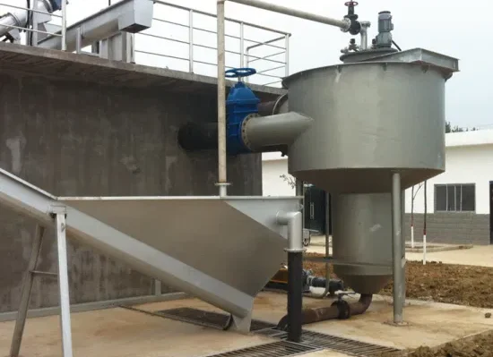
Grit Removal in Wastewater Treatment
Every treatment plant receives a steady load of dense inorganic solids alongside its organic wastewater: sand, gravel, silt, eggshells, bone fragments, coffee grounds, and the road grit that washes into collection systems after every storm. These particles are small enough to pass through bar screens but heavy enough to abrade pump impellers, wear out mixers, fill digesters and aeration basins, and accumulate in channels until hydraulic capacity is lost. Grit removal is the unit process that intercepts them, and it sits within preliminary treatment immediately downstream of screening.
Mechanical grit removal systems are employed to ensure these abrasive materials are effectively separated from the organic load. The design considerations for grit removal systems are crucial, with factors like particle size, system capacity, and removal efficiency dictating the choice of technology. Optimizing grit removal efficiency through tailored design and operation is paramount, as it directly influences the plant’s performance and longevity. The integration of grit removal as a component of primary wastewater treatment underscores its importance in safeguarding downstream processes, including biological treatment phases and sludge handling.
The central engineering challenge is selectivity rather than capture. It is straightforward to settle out everything heavier than water; the difficulty is settling the inorganic fraction while allowing organic solids to remain suspended and continue downstream, because organic material captured alongside the grit turns a disposal problem into an odor problem. Every technology described below is, at bottom, a different approach to that same separation.
Key Takeaways
- Grit removal is essential for protecting wastewater infrastructure and optimizing plant operation.
- Mechanical systems are designed for the efficient separation of grit from organic wastewater content.
- Effective grit removal is integral to the primary treatment phase and influences overall treatment efficiency.
Grit Removal Fundamentals
In wastewater treatment processes, the removal of grit is essential to protect equipment and improve efficiency. Grit comprises a variety of materials that can cause significant issues in the treatment process if not adequately addressed.
Importance of Grit Removal
Grit removal is a critical step in preserving the integrity of water treatment systems. It prevents the accumulation of inorganic materials that can cause wear and tear on mechanical components, leading to increased maintenance costs and potential downtime. By effectively removing grit, they ensure that subsequent treatment processes, such as biological treatment and clarification, can operate at optimal efficiency without interference from abrasive particles.
Grit Characteristics and Sources
Grit in wastewater predominantly consists of sand, silt, eggshells, bone chips, seeds, and coffee grounds. Its primary sources include soil erosion, urban runoff, and household waste that enters the wastewater stream. The characteristics of grit, such as size, hardness, and specific gravity, influence the selection of removal technologies and the design of removal systems. Grit particles are typically heavier than organic particulates and settle quickly in quiescent conditions, making them distinct in their behavior and removal requirements within wastewater grit removal systems.
Classical design practice assumed a clean silica particle with a specific gravity near 2.65 and a design cut point around 0.21 mm, corresponding to 65 mesh. Field experience has substantially revised that picture. Real grit arrives coated with grease and organic material, which lowers its effective specific gravity and settling velocity, and a large share of the material causing downstream damage is finer than the traditional cut point. Modern practice increasingly targets 0.15 mm or even 0.10 mm, and characterizes influent by settling velocity distribution rather than by sieve size alone, because two samples with identical particle size distributions can behave very differently depending on how much organic coating they carry.
Subcategory Overview: Grit Removal Topics
The material below covers the grit removal category from several angles: the chambers themselves, the process fundamentals, the equipment suppliers, and the plant-scale application questions. Each subsection addresses a distinct aspect of specifying and operating this equipment.
Grit Chamber Design and Types
Coverage of the grit chamber in wastewater treatment focuses on the vessel itself: its geometry, the flow regime it establishes, and how that geometry determines what settles and what carries through. Horizontal channels rely on maintaining a constant approach velocity across the full flow range, which requires a downstream control section such as a proportional weir or a Parshall flume. Aerated chambers use diffused air along one wall to induce a spiral roll, adding a controllable variable that horizontal channels lack. Vortex units generate a forced or free rotational flow in a circular basin, concentrating grit at the center for extraction. Each geometry has a characteristic detention time, headloss, and footprint, and the choice among them is usually settled by site constraints as much as by removal performance.
The Grit Removal Process
A process-level treatment of grit removal in wastewater treatment follows the material from the point it enters the chamber to the point it leaves the site. Separation in the chamber is only the first stage; the captured slurry must then be pumped or conveyed out, classified to separate grit from carried-over organics, washed to reduce volatile content, dewatered to cut weight and volume, and finally hauled. A facility that separates grit well but washes it poorly ends up with an odorous dumpster and complaints, which is why the downstream train deserves as much design attention as the chamber. Removal efficiency should be evaluated on what actually leaves the site as clean grit, not on what the chamber captures.
Grit Chamber Fundamentals
An introductory treatment answering what is grit chamber in wastewater treatment is the right starting point for operators and newer engineers, establishing the basic vocabulary before the design detail. A grit chamber is a basin or channel deliberately sized so that flow slows enough for dense inorganic particles to fall out of suspension while lighter organic solids stay entrained and continue to the next process. Everything else in the design follows from that single principle: detention time, velocity control, chamber shape, and extraction method all exist to make that separation happen reliably across a flow range that may vary five-fold in a day.
Grit Removal Fundamentals
Similarly, material answering what is grit removal in wastewater treatment approaches the same subject from the process rather than the vessel, explaining why the step exists at all. The justification is entirely economic and mechanical: grit that passes the headworks does not disappear, it accumulates. It scours pump impellers and volutes, wears through mixer blades, settles in channels and reduces their capacity, occupies volume in digesters that should hold active biomass, and eventually requires expensive tank cleanouts. Every dollar spent on effective grit removal displaces several dollars of downstream wear and cleaning.
Plant-Scale Grit Chamber Application
Guidance on the grit chamber for wastewater treatment plant installations addresses how the chamber fits the specific facility: how many units the plant needs for redundancy, how they are isolated for cleaning, how the hydraulic profile accommodates the chamber’s headloss, and how the grit extraction equipment ties into the plant’s conveyance and washing train. Site-specific factors dominate at this level. A plant with a combined sewer system and sanded winter roads faces a grit load an order of magnitude above a separate sanitary system in a temperate climate, and the equipment that suits one will fail at the other.
Gravity Grit Chambers
Gravity Grit Chambers rely purely on quiescent settling without aeration or induced rotation, which makes them the simplest and least energy-intensive configuration available. Square and rectangular detritor-style basins with a rotating rake mechanism fall into this family, as do the horizontal channels described elsewhere in this article. Their limitation is sensitivity to flow variation, since settling performance depends directly on surface loading rate and detention time, both of which change with flow. They remain a sound choice at facilities with stable flow, adequate site area, and a preference for minimal mechanical and energy complexity.
Equipment Manufacturers
The Top Grit Removal Equipment Manufacturers area compares the major suppliers across chamber technology, extraction and classification equipment, documented removal performance, and service support. Grit systems are one of the equipment categories where manufacturer performance claims warrant close scrutiny, because removal efficiency figures depend heavily on the particle size and specific gravity assumed in the test, and a system quoted at high efficiency on 0.21 mm clean silica may perform very differently on 0.15 mm organically coated grit. Asking for performance data at the specific cut point the plant needs, and for references at facilities with comparable influent, separates suppliers more effectively than headline efficiency numbers.
Mechanical Grit Removal Systems
Mechanical grit removal systems are an integral part of wastewater treatment, designed to separate heavier inorganic materials, such as sand, silt, and gravel, from organic waste. These systems improve the efficiency of downstream processes by preventing abrasion and accumulation of grit in equipment and pipelines.
Horizontal Flow Grit Chambers
Horizontal flow grit chambers are the simplest form of grit removal systems. Wastewater flows through a channel where the velocity is controlled to allow grit to settle to the bottom while organic materials remain suspended. The settled grit is then removed by a mechanical conveyor system. These chambers are appreciated for their simplicity and low energy requirements.
- Construction: Typically rectangular.
- Flow regulation: Essential for efficient grit separation.
The design velocity is conventionally held near 1 ft/s, high enough that organic solids remain in suspension and low enough that grit settles, with detention time typically in the range of 45 to 90 seconds at design flow. Holding that velocity across a varying flow is the whole engineering problem, and it is why a proportional weir or flume control section is not optional equipment on this configuration.
Longitudinal Grit Chambers
Longitudinal grit chambers function similarly to horizontal flow chambers but are more extensive in size. They are designed for use in larger treatment facilities where greater volumes of wastewater are processed. Longitudinal chambers are often equipped with mechanical scrapers that move collected grit toward a hopper for removal.
- Design: Long, narrow channels.
- Capacity: Suitable for high-volume wastewater treatment.
Vortex Type Grit Removal
The Vortex-type grit removal systems utilize rotational flow to separate grit from wastewater. By introducing a vortex flow pattern, grit spirals downward to the chamber bottom, while lighter organic material remains suspended. These systems boast high efficiency in grit separation, even at variable flow rates.
- Efficiency: Superior due to the rotational flow dynamics.
- Versatility: Effective across a range of flow conditions.
Detention time in a vortex unit is very short, often well under a minute, which is what allows the compact footprint and low headloss that make them the dominant retrofit choice. The trade-off is that performance depends on operating inside the manufacturer’s design flow envelope, and a unit selected for a peak that rarely occurs will spend most of its life below the flow at which its rotational pattern is fully established.
Aerated Grit Chambers
Aerated grit chambers introduce air into the wastewater to create a spiral flow pattern, which aids in the separation of grit from organics. By controlling the airflow, heavier particles settle while organics stay suspended. These chambers are effective due to the controlled environment they provide.
- Aeration: Crucial for creating the necessary spiral flow.
- Separation process: Enhanced by the air-induced water motion.
Typical design detention is 2 to 5 minutes at peak flow, with air supplied along one wall at a rate commonly in the range of 3 to 8 cubic feet per minute per foot of tank length. The adjustable air rate is the configuration’s principal advantage, because it gives operators a direct control over the selectivity of separation: too little air and organics settle with the grit, too much and fine grit stays suspended and passes through.
Grit Handling and Disposal
In the context of wastewater treatment, grit handling, and disposal are critical steps following the grit removal process, ensuring the safe and efficient management of grit extracted from the wastewater.
Grit Washing and Dewatering
After grit is separated from the main wastewater flow using various grit removal systems, it often contains organic material and needs to be washed. The washing process reduces odor and facilitates effective disposal. Subsequent dewatering is performed to minimize the volume and weight of the grit, which reduces transport and disposal costs.
Washing performance is measurable and should be specified rather than assumed. Volatile content in washed grit is the standard indicator, with well-washed material typically falling below roughly 15 percent volatile solids, while poorly washed grit can exceed 50 percent and will generate odor within a day of sitting in a container. Cyclone separators followed by a screw or reciprocating rake classifier are the common arrangement, with the cyclone concentrating the slurry and the classifier providing the washing and dewatering action.
Grit Transport
Once washed and dewatered, the grit must be transported to a dedicated disposal site. Transportation is typically done using enclosed vehicles to prevent spillage and odor release. Handling should comply with local regulations to mitigate environmental impact.
Grit Disposal Methods
Disposal methods for grit include landfilling, where it is buried in designated areas, and reclamation, where the material can be reused in construction or other applications. The chosen method should align with environmental guidelines and minimize the potential for groundwater contamination.
Design Considerations for Grit Removal Systems
When integrating a grit removal system in a wastewater treatment facility, it is imperative to focus on efficiency and long-term sustainability. Designers must consider hydraulic capacity, structural integrity, and the suitability of materials used.
Hydraulic Design
The hydraulic design of grit removal systems ensures that all incoming water is exposed to the grit extraction process. Optimal flow conditions are critical for efficient operation. For example, Cyclonic Degritters are designed to utilize centrifugal force, separating grit efficiently and effectively from water. Moreover, specific attention is required for the positioning of grit removal pumps to secure consistent flow rates and prevent system clogs.
Structural Design
The structural design of these systems has to sustain the harsh operating conditions found in wastewater treatment. This includes the ability to withstand abrasive materials and chemical corrosion. Notably, the installation of Cyclonic Degritters demands robust structural support, given the stresses imposed by cyclical motion and material weight.
Material Selection
Selecting appropriate materials for the fabrication of grit removal components cannot be understated. Materials need to resist wear and minimize maintenance demands. For instance, pumps employed in grit removal should be constructed from materials that can handle the abrasive nature of the grit, such as certain high-grade stainless steels or specialized alloys.
Selection and Specification Framework
Step One: Characterize the Grit Before Selecting Equipment
The single most consequential step is also the one most often skipped. Sample the influent across seasons and weather conditions, and characterize it by particle size distribution, specific gravity, organic coating, and ideally settling velocity distribution. Quantify the load itself, since grit generation varies enormously between service areas: separate sanitary systems commonly fall in a range of a few cubic feet per million gallons, while combined systems with sanded winter roads can generate an order of magnitude more. Equipment sized on a textbook assumption rather than on measurement is the root cause of most chronically overloaded grit systems.
Step Two: Set the Design Cut Point Deliberately
Decide what size particle the system is expected to capture, and state it in the specification along with the specific gravity it assumes. The traditional 0.21 mm cut point at 2.65 specific gravity leaves a meaningful fraction of damaging material in the flow. Where downstream equipment has suffered, or where digester and channel cleanouts are frequent, a finer cut point of 0.15 mm or below is usually justified. Every reduction in cut point increases the required detention time or reduces the allowable loading rate, so this decision drives the sizing of everything that follows.
Step Three: Match Chamber Type to Site and Flow Regime
Horizontal channels suit stable flows and sites with room, provided a proper velocity control section is installed. Aerated chambers handle wide flow variation and give operators an adjustable control over selectivity, at the cost of air supply energy and diffuser maintenance. Vortex units offer the smallest footprint and lowest headloss, which is why they dominate retrofits into constrained sites, but they depend on staying inside their design flow envelope. Gravity and detritor-style basins are simple and low-energy but sensitive to flow variation. Site area and available head frequently decide this before removal performance does.
Step Four: Design the Washing and Dewatering Train to Match
Grit capture and grit handling should be specified as one system. Size the pumping, cyclone, and classifier capacity for peak grit generation rather than for the average, since the storm event that produces the most grit is also the one during which the equipment is most likely to be overwhelmed. Specify the volatile content target for washed grit and require the supplier to demonstrate it. Confirm the hauling arrangement and container placement early, because a classifier discharging to an inaccessible location creates a permanent operating problem.
Step Five: Provide Redundancy and Access
Grit chambers accumulate material that eventually requires manual cleaning, and a facility with a single chamber and no bypass has no way to do that work without exposing downstream equipment to raw influent. Provide either duplicate chambers or a bypass channel with isolation gates that actually seat. Confirm that every submerged mechanical component has a defined removal path and a rated hoisting provision, and that confined space entry procedures can be executed safely. Grit equipment fails from deferred maintenance more often than from design deficiency, and inaccessible equipment is maintained late or not at all.
Step Six: Consider the Whole Headworks Together
Screening and grit removal interact in both directions. Finer screening upstream reduces the rag load that fouls grit extraction equipment, while grit carryover shortens screen mechanism life. The relevant selection criteria for the upstream stage are covered in our guide to screening equipment, and the broader stage context in the preliminary treatment overview. Where wet weather flows swing widely enough to push a grit system outside its operating envelope, flow equalization upstream can be a more economical answer than oversizing the chamber.
Optimizing Grit Removal Efficiency
Optimizing grit removal is crucial for protecting downstream processes in wastewater treatment. Efficient grit removal prevents abrasive wear on equipment and minimizes operational issues.
Performance Evaluation
To boost the efficiency of grit removal systems, it’s essential to begin with a thorough performance evaluation. Regular assessments should be carried out to measure the effectiveness of the existing system in removing grit particles of various sizes. Factors such as flow rate, particle size distribution, and specific gravity must be considered to understand the system’s capability. Detailed performance data help in making informed decisions for enhancements or replacements.
Advanced Technologies
Innovative technologies play a pivotal role in advancing the efficiency of grit removal. The shift from traditional systems to aerated grit removal methodologies offers significant improvements. The aerated approach uses controlled air flow to separate heavy grit particles from organic materials more effectively, thereby increasing removal efficiency. These innovative systems often lead to reduced energy consumption and operational costs. For instance, replacing an older system with a vortex system resulted in energy savings of around 70 percent annually.
The purpose of grit removal in wastewater treatment is to safeguard downstream equipment and improve the overall efficiency of the treatment process. Advanced grit removal technologies, when properly implemented, assist facilities in achieving these goals more reliably.
Comparative Analysis of Grit Removal Technologies
Grit removal is an essential component of wastewater treatment, aiming to eliminate sand, silt, and other small particles from the wastewater stream. Various technologies have been developed to improve the efficiency and effectiveness of this process.
Detritors are one such technology designed with a sloped bottom that allows settled grit to be swept into a hopper for removal. They often employ a rotating scraper mechanism that aids in the collection process. Detritors are known for their reliability and are commonly used in municipal wastewater treatment plants.
In contrast, Aerated Grit Chambers introduce air into the wastewater to reduce the settling velocity of organic material, hence prioritizing the removal of denser inorganic grit particles. This method allows for a distinction between organic and inorganic materials, though the presence of excess organic matter can inhibit efficiency.
- Vortex-Type Grit Removal Systems create a circular flow to encourage the settlement of heavy particles. Here’s how they compare:
- Efficiency: Vortex systems are highly efficient due to their rotational flow, which forces grit to the outer edges for removal.
- Maintenance: These systems are relatively low-maintenance once properly installed.
- Space: They require less space than traditional rectangular chambers.
Gravity Settlers, another technology, rely on the density difference where grit settles out by gravity. While they are simple and cost-effective, their performance can be influenced by process fluctuations.
| Technology | Efficiency | Maintenance Needs | Space Requirement |
|---|---|---|---|
| Detritors | Moderate-High | Moderate | Moderate |
| Aerated Grit Chambers | High (selective removal) | High | Large |
| Vortex Systems | High | Low | Low |
| Gravity Settlers | Moderate | Low | Variable |
Each grit removal technology has its own set of advantages and limitations based on factors such as plant size, effluent requirements, and capital and operational costs. The choice of technology must be tailored to the specific needs of the treatment facility.
| Site or Flow Condition | Configuration That Usually Fits | Reason | Watch For |
|---|---|---|---|
| Stable flow, ample site area, limited energy budget | Horizontal channel or gravity detritor | Simplest mechanically, lowest energy demand | Velocity control section is mandatory, not optional |
| Wide diurnal and wet weather flow variation | Aerated chamber | Adjustable air rate gives operators direct control over selectivity | Air supply energy; diffuser fouling and replacement |
| Constrained footprint, retrofit, limited available head | Vortex unit | Smallest footprint and lowest headloss of the common options | Performance depends on staying inside the design flow envelope |
| Combined sewer, heavy seasonal road sand | Aerated or vortex with oversized handling train | Grit load can exceed separate sanitary systems by an order of magnitude | Handling and washing capacity, not chamber capacity, is usually the bottleneck |
| Fine grit causing downstream wear despite an existing system | Finer design cut point, typically 0.15 mm or below | Traditional 0.21 mm cut leaves damaging material in the flow | Longer detention or lower loading rate required; resize accordingly |
| Odor complaints at the grit container | Upgraded washing and classification, not a new chamber | Odor comes from organic carryover, which is a washing problem | Specify and verify a volatile content target for washed grit |
Field Notes
Commissioning Considerations
Witness performance at both minimum and maximum design flow rather than at whatever flow happens to arrive on the test day, since selectivity fails at opposite ends of the range for opposite reasons. Verify that a horizontal channel’s control section actually holds the design velocity across the flow range by measuring depth and calculating velocity at several conditions. Confirm that the grit washer discharges material with visibly low organic content and sample it for volatile solids to establish a baseline. Check that every isolation gate seats, that the bypass functions, and that the classifier discharge lands where the hauling container will actually sit.
Common Specification Mistakes
- Assuming grit quantity instead of measuring it. Service area variation is large enough that assumed values regularly miss by a factor of five or more.
- Accepting a manufacturer’s efficiency figure without its cut point. High removal at 0.21 mm clean silica says little about performance on 0.15 mm organically coated grit.
- Omitting the velocity control section on a horizontal channel. Without it, velocity varies with flow and the chamber either passes grit or captures organics.
- Sizing the washing train on average rather than peak grit load. The storm that generates the most grit is when the handling equipment is most likely to be overwhelmed.
- Selecting a vortex unit for a flow range wider than its envelope. Compact footprint is no advantage if the unit spends most of its life below its effective flow.
- Treating odor as a chamber problem. Odor at the container is almost always inadequate washing, not inadequate separation.
- Providing no redundancy or bypass. Chambers require periodic manual cleaning, and there is no downstream process that tolerates raw influent meanwhile.
Operations and Maintenance Comparison
Horizontal and gravity chambers concentrate maintenance on the collector mechanism, the chain and flight or rake drive, and periodic manual cleaning of accumulated material at the ends of the channel. Aerated chambers add diffuser maintenance and blower service, and the diffusers foul with grease in a way that gradually degrades the spiral pattern without any obvious alarm. Vortex units have the fewest submerged moving parts but depend entirely on the grit pump and cyclone downstream, both of which handle an abrasive slurry and wear at a predictable rate. Across every configuration, the classifier and cyclone are the components that fail first, and budgeting for wear parts on a defined interval is far more effective than replacing on failure.
Troubleshooting by Symptom
Grit accumulating in aeration basins, digesters, and channels indicates the chamber is operating outside its velocity or detention envelope, that the design cut point is too coarse for the actual grit, or that extraction equipment cannot keep pace with capture. High organic content in removed grit, usually first noticed as odor at the container, points to capture velocity that is too low, excessive aeration in an aerated chamber, or an underperforming washer. Rapid wear on the grit pump and cyclone suggests the material is coarser or the load heavier than the equipment was selected for. Declining removal with no equipment change frequently traces to a shift in influent character, such as a new industrial contributor or a change in road sanding practice, rather than to the equipment itself.
Pro Tip: Weigh Hauled Grit and Test Its Volatile Content
Most plants estimate grit removal from how often the container is hauled, which reveals nothing about whether the system is actually working. Recording hauled weight per load, normalized to millions of gallons treated, and periodically testing volatile solids in the washed grit turns this into a measurable process with two independent indicators. Weight tells you how much is being captured and exposes collection system changes and seasonal patterns; volatile content tells you how well it is being washed and predicts odor complaints before they arrive. Together they also supply the documented grit generation rate the next headworks design will need, instead of a textbook assumption.
Design Details and Standards
Sizing Methodology
Grit systems are sized on peak flow rather than average, because carryover during peak conditions is what damages downstream equipment. Establish peak hour and peak wet weather flow, then select the design cut point and its assumed specific gravity. Size the chamber for the detention time or surface loading rate required to settle that particle at peak flow, and verify that the configuration maintains its separating flow regime at minimum flow as well, since selectivity fails at both ends. Confirm the headloss through the chamber fits the available hydraulic profile without surcharging the incoming sewer. Then size the grit pumping, cyclone, classifier, and conveyance for peak grit generation, and verify the container and hauling arrangement can absorb that peak without interruption.
Key Parameters
- Horizontal channel velocity: approximately 1 ft/s maintained across the flow range by a proportional weir or flume control section.
- Horizontal channel detention: commonly 45 to 90 seconds at design flow.
- Aerated chamber detention: typically 2 to 5 minutes at peak flow.
- Aerated chamber air supply: commonly 3 to 8 cubic feet per minute per foot of tank length, adjustable to tune selectivity.
- Vortex detention: often under a minute, with performance sensitive to remaining inside the design flow envelope.
- Design cut point: traditionally 0.21 mm at specific gravity 2.65; modern practice frequently targets 0.15 mm or finer.
- Washed grit volatile content: a target below roughly 15 percent is a reasonable specification and should be verified rather than assumed.
- Grit generation: highly variable by service area, with combined systems and sanded roads producing far more than separate sanitary systems; measure rather than assume.
All figures above are typical or approximate design ranges and should be confirmed against site sampling, the governing state standard, and manufacturer data for the specific equipment.
Applicable Standards and References
Recommended Standards for Wastewater Facilities, the Ten States Standards, governs grit chamber provisions, velocity control, redundancy, and bypass requirements in many states. WEF Manual of Practice No. 8 and ASCE Manual of Practice No. 76, Design of Municipal Wastewater Treatment Plants, provide the underlying design methodology for grit removal and handling. EPA wastewater technology fact sheets on grit removal give a concise treatment of the available configurations and their applications. NFPA 820, Standard for Fire Protection in Wastewater Treatment and Collection Facilities, establishes hazardous area classification and ventilation requirements for headworks structures including grit chambers. OSHA 29 CFR 1910.146 governs permit-required confined space entry for chamber cleaning, and 29 CFR 1910.147 covers lockout and tagout of the collector and classifier equipment. Local solid waste regulations govern grit disposal and any beneficial reuse of the washed material.
Specification Checklist
- Design average, peak hour, and peak wet weather flows, with the data source stated
- Measured grit characterization: particle size distribution, specific gravity, organic content, and generation rate across seasons
- Design cut point and the specific gravity it assumes, stated explicitly
- Chamber configuration and the site or flow rationale for it
- Velocity control section for horizontal configurations, or air supply range for aerated
- Headloss through the chamber, checked against the hydraulic profile
- Grit pumping, cyclone, classifier, and conveyance capacity at peak generation
- Volatile content target for washed grit, with a demonstration requirement
- Container placement, access, and hauling arrangement
- Redundancy: number of chambers, bypass provisions, isolation gates
- Removal path and rated hoisting provision for every submerged component
- Materials of construction for abrasion and corrosion resistance, including wear parts
- Ventilation and NFPA 820 area classification documentation
- Odor control provisions for the chamber and the grit handling area
Integration with Primary Wastewater Treatment
During the primary stage of wastewater treatment, the integration of grit removal is a critical step in ensuring the efficiency of subsequent processes. Grit, consisting of sand, gravel, and other heavy materials, can cause significant damage to equipment and interfere with the overall treatment system if not removed early on.
Primary clarifiers are a central component in this stage, serving to reduce the velocity of wastewater which allows solids to settle. The settled material, known as primary sludge, is then collected for further treatment or disposal. Alongside organic and inorganic materials, grit is one of the solids targeted by this process.
Here’s a simple breakdown of the process involved in the primary treatment stage:
- Influent Entry: Wastewater flows into the treatment plant.
- Grit Removal: Heavy particles settle by gravity and are removed.
- Primary Sedimentation: Wastewater moves to the primary clarifier where further settling occurs.
- Collection of Primary Sludge: Settled solids are removed from the bottom.
The function of primary clarifiers is not just limited to sedimentation. In the context of primary treatment, these clarifiers facilitate initial filtration, providing a quasi-cleansing phase before the water proceeds to secondary treatment.
During primary treatment, materials such as fats, oils, greases, and larger solids are removed. The efficacy of this removal can be attributed to the simplicity yet effectiveness of the primary wastewater treatment process, which typically involves physical methods and simple settling techniques.
An understanding of what is removed during primary wastewater treatment—including grit—bolsters the effectiveness of the entire system, leading to more successful secondary and tertiary processes.
Below is a visual representation of the primary treatment of wastewater diagram:
[Influent Entry] → [Grit Chamber] → [Primary Clarifier] → [Collection of Sludge]
It’s this sequential approach that characterizes primary treatment and paves the way for more advanced methods used in secondary and tertiary wastewater treatment.
Frequently Asked Questions
How do grit removal systems enhance the efficacy of wastewater treatment plants?
Grit removal systems are essential for safeguarding mechanical equipment from abrasion and ensuring the smooth operation of downstream processes. By extracting heavy materials like sand and gravel early in the treatment sequence, these systems prevent excessive wear and maintenance on equipment.
Which processes are involved in the treatment of grit found in municipal sewage?
The treatment of gritty materials typically involves sedimentation techniques where the heavier grit particles settle out by gravity. This is often followed by mechanical removal methods such as grit classifiers or concentrators, which isolate and remove the grit from the system, thus preparing the water for subsequent treatment stages.
Why is grit removal a critical step in the wastewater treatment process?
Removing grit is crucial because it prevents sediment accumulation in basins and channels, which can reduce treatment capacity and effectiveness. It also protects pumps and other mechanical components from damage due to the abrasive nature of grit, thus ensuring the longevity and efficiency of wastewater treatment plants.
How does the grit removal process compare with other preliminary treatment methods such as screening?
While screening is aimed at removing larger, floating debris, grit removal targets the denser, smaller particles that screens do not catch. Grit removal complements screening as part of the preliminary treatment to improve overall wastewater treatment performance. Together, they form an integrated approach to prevent damage and clogging in the treatment plant's subsequent units.
Conclusion
Key Takeaways
- Selectivity is the engineering problem, not capture — settling everything dense is easy; settling grit while letting organics pass is what every configuration is actually trying to do.
- Measure the grit, don’t assume it — particle size, specific gravity, organic coating, and generation rate vary enormously by service area, and assumed values are the commonest cause of an overloaded system.
- State the design cut point explicitly — the traditional 0.21 mm figure leaves damaging fine material in the flow, and a manufacturer’s efficiency claim means nothing without the particle it was measured on.
- Velocity control is mandatory on horizontal chambers — without a proportional weir or flume, velocity tracks flow and the chamber either passes grit or captures organics.
- Odor is a washing problem, not a chamber problem — specify a volatile content target for washed grit and verify it, rather than replacing a chamber that is separating adequately.
- Size the handling train for peak, not average — the storm producing the most grit is exactly when pumping, cyclone, and classifier capacity is most likely to be the bottleneck.
Grit removal is a small line item in a treatment plant’s capital budget and a disproportionately large influence on its maintenance costs. Grit that passes the headworks does not disappear; it wears through pump impellers, erodes mixer blades, consumes digester volume, and fills channels until capacity is lost, and every one of those consequences costs more to fix than the equipment would have cost to specify properly in the first place.
The approach that works is consistent across configurations: sample and characterize the influent rather than assuming a textbook particle, set the design cut point deliberately and state it in the specification, choose a chamber configuration that suits the site’s flow variability and available head, size the washing and handling train for peak generation rather than average, and provide the redundancy that lets the equipment be cleaned and maintained. Facilities that measure hauled weight and washed volatile content have the two indicators needed to know whether any of it is working.