
RO Systems & Buying Guides: Complete Guide to Reverse Osmosis
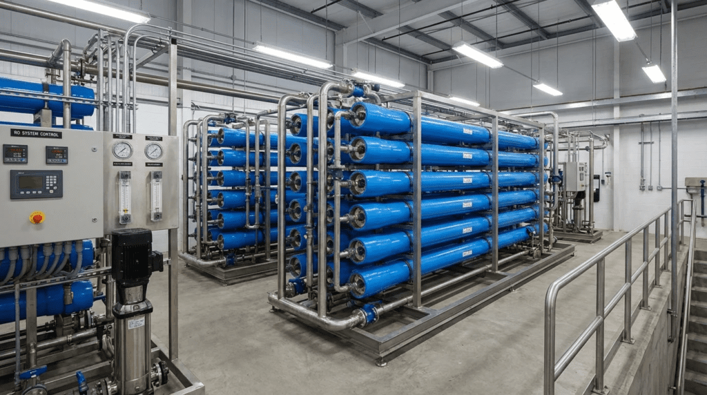
Introduction
Membrane separation technologies have become the backbone of modern municipal desalination, industrial process water generation, and advanced wastewater reuse. However, misjudging feed water chemistry or specifying the wrong membrane configuration can lead to catastrophic fouling, severe hydraulic imbalances, and operational expenses (OPEX) that rapidly eclipse capital cost savings. To navigate RO Systems & Buying Guides: Complete Guide to Reverse Osmosis, engineers must look past generic vendor sizing curves and deeply understand the interplay between flux rates, osmotic pressure, concentration polarization, and pretreatment constraints.
Equipment selection sits on top of process understanding, not in place of it. The foundational treatment of reverse osmosis as a water purification process establishes why applied pressure must exceed osmotic pressure before permeate is produced — the relationship that determines every constraint discussed below, from why seawater recovery caps near 50% to why the tail element is always the one that scales. A buyer who has not internalised that relationship cannot evaluate competing bids, because the differences between them will look like specifications rather than consequences.
Reverse osmosis is not a monolith; it is an ecosystem of specialized components and configurations tailored to specific influent conditions and effluent purity requirements. A system designed for high-salinity seawater will fail mechanically and financially if applied to a low-TDS industrial effluent, just as a single-pass brackish water system cannot meet the stringent silica and conductivity limits of high-pressure boiler feed water.
This pillar guide provides a comprehensive, vendor-neutral framework for municipal and industrial engineers to evaluate, compare, and specify the diverse array of RO technologies available today. It covers the landscape of subcategories—from distinct operational configurations to critical sub-components—delivering the technical depth required to optimize lifecycle costs, ensure regulatory compliance, and guarantee reliable hydraulic performance.
Subcategory Landscape — Types, Technologies & Approaches
The reverse osmosis landscape is categorized primarily by feed water salinity, desired permeate purity, system packaging, and operational efficiency mechanisms. Engineers must navigate this landscape by first defining their boundaries: hydraulic capacity, osmotic pressure limits, and scaling potential. Selecting the right foundational subcategory dictates everything from the required high-pressure pump metallurgy to the frequency of membrane replacement.
Below are the major technological variants, equipment configurations, and critical sub-systems that comprise modern industrial and municipal RO installations.
Brackish Water Reverse Osmosis (BWRO) Systems
Brackish Water Reverse Osmosis (BWRO) Systems are the workhorses of inland municipal groundwater treatment and general industrial water purification. They are typically applied to feed waters with Total Dissolved Solids (TDS) ranging from 1,000 to 10,000 mg/L. Operating at relatively moderate pressures—typically between 150 and 400 psi (10 to 28 bar)—these systems utilize standard Thin-Film Composite (TFC) polyamide membranes.
BWRO systems are highly versatile and can achieve high recovery rates (typically 75% to 85%, and up to 90% depending on silica and scaling salt limitations). They are generally utilized for drinking water production, food and beverage ingredient water, and cooling tower makeup. The primary engineering constraint in BWRO design is sparingly soluble salts (e.g., calcium carbonate, calcium sulfate, barium sulfate, and silica). Because osmotic pressure is comparatively low, the limiting factor for system recovery is usually the Langelier Saturation Index (LSI) or Stiff-Davis Index in the tail elements. Appropriate antiscalant dosing and conservative flux design (typically 14-18 GFD or 24-30 LMH) are critical.
Seawater Reverse Osmosis (SWRO) Systems
Designed for highly saline feed waters (typically 35,000 to 45,000 mg/L TDS), Seawater Reverse Osmosis (SWRO) Systems operate at extreme hydraulic pressures ranging from 800 to 1,200 psi (55 to 83 bar) to overcome immense osmotic pressure. These systems are the standard for coastal municipal desalination and marine applications. SWRO membranes are denser, offering higher salt rejection (often >99.7%) but operating at significantly lower permeate flux rates (typically 8-10 GFD or 13-17 LMH) to prevent rapid fouling and excessive concentration polarization.
SWRO system recovery is typically limited to 40% to 50% due to the exponential rise in osmotic pressure as the feed water concentrates into brine. Due to the extreme operational pressures, all high-pressure piping, pump wetted parts, and valving must be constructed from high-grade, corrosion-resistant alloys, such as duplex or super duplex stainless steel. SWRO specification is heavily weighted toward energy optimization, making the integration of energy recovery technologies an absolute necessity.
High-Recovery Reverse Osmosis Systems
When water scarcity, stringent discharge regulations, or Minimal Liquid Discharge (MLD) goals dictate, engineers turn to High-Recovery Reverse Osmosis Systems. These include advanced configurations such as Closed Circuit Reverse Osmosis (CCRO) or ultra-high-pressure RO (UHPRO). Instead of standard steady-state continuous flow, CCRO systems recycle the brine stream back to the feed pump, progressively increasing system salinity until a predetermined pressure or concentration setpoint is reached, at which point the system purges the highly concentrated brine and restarts the cycle.
These systems push recovery limits up to 95-98% on brackish or industrial wastewater feeds. By continuously varying the salinity and crossflow velocity within the elements, CCRO naturally disrupts the formation of scaling crystals and organic fouling layers. These systems are highly applicable in industrial wastewater reuse and cooling tower blowdown treatment. However, they require highly sophisticated controls, automated valving capable of continuous cycling, and specialized ultra-high-pressure membranes (rated up to 1,740 psi / 120 bar) for the final concentration stages.
Double Pass Reverse Osmosis Systems
For applications requiring ultra-pure water (UPW)—such as power plant high-pressure boiler feed, microelectronics manufacturing, and pharmaceutical Water-For-Injection (WFI)—a single pass is rarely sufficient. Double Pass Reverse Osmosis Systems address this by taking the permeate (product water) from the first RO stage and feeding it directly into a second RO system.
Because the feed to the second pass is already highly purified (often <20 mg/L TDS), the second pass operates at very low pressure (often <100 psi) and achieves extremely high recovery (85-95%). To facilitate the removal of carbon dioxide and optimize boron or silica rejection, caustic (NaOH) is frequently dosed between the first and second pass to elevate the pH. The second pass concentrate is essentially high-quality water and is practically always recycled to the front of the first pass to maximize overall system recovery.
Containerized Reverse Osmosis Plants
When rapid deployment, remote location installation, or decentralized municipal treatment is required, Containerized Reverse Osmosis Plants offer a modular, plug-and-play solution. These systems integrate the pre-treatment (media or UF), RO skids, clean-in-place (CIP) equipment, chemical dosing, and motor control centers (MCC) into standard 20-foot or 40-foot ISO shipping containers.
Containerized systems significantly reduce civil construction costs and site-installation time. They are widely used in mining camps, military deployments, disaster relief, and expanding industrial facilities lacking interior floor space. Engineers specifying containerized units must pay close attention to internal climate control (HVAC)—as extreme ambient temperatures can affect electronic drives, chemical stability, and membrane performance—as well as ensuring adequate physical clearance for operators to perform maintenance and membrane change-outs within the confined space.
Integrated Membrane Systems (UF-RO)
The success of an RO system is overwhelmingly dependent on its pretreatment. Integrated Membrane Systems (UF-RO) utilize Ultrafiltration (UF) or Microfiltration (MF) as the direct pretreatment step prior to reverse osmosis. Unlike conventional media filtration, which may pass sub-micron particles during pressure spikes, UF provides an absolute physical barrier to suspended solids, bacteria, and large colloids.
This integration virtually guarantees an RO feed water Silt Density Index (SDI) of less than 3.0 (and often <1.0), regardless of fluctuations in raw water turbidity. UF-RO systems are the industry standard for surface water desalination, tertiary wastewater reuse, and any application subject to variable influent quality. While capital costs for UF pretreatment are higher than for multi-media filters, the resulting stabilization of RO operation—manifesting as reduced CIP frequency, extended RO membrane life, and allowable higher RO design flux—yields a lower total lifecycle cost.
RO Energy Recovery Devices (ERDs)
Particularly in SWRO, the concentrate (brine) stream exits the membrane vessels at nearly the same high pressure as the feed stream. Wasting this pressure across a throttle valve is economically unviable. RO Energy Recovery Devices (ERDs) are mechanical components designed to capture this residual hydraulic energy and transfer it back to the feed stream.
The two main categories are centrifugal devices (like Francis turbines or Pelton wheels) and isobaric devices (such as pressure exchangers). Isobaric ERDs are currently the industry standard for SWRO, offering energy transfer efficiencies of up to 98%. By utilizing an ERD, the high-pressure pump only needs to pressurize roughly half the total feed flow (the permeate portion), drastically reducing the electrical load from typical ranges of 6–8 kWh/m³ down to 2.5–3.5 kWh/m³. ERDs are vital for SWRO but are also increasingly specified in large-scale high-pressure BWRO systems.
Fouling-Resistant RO Membranes
Industrial wastewaters and tertiary municipal effluents often contain high levels of organic matter, biological precursors, and complex hydrocarbons that rapidly blind standard TFC membranes. Fouling-Resistant RO Membranes are explicitly engineered to combat this. They feature altered surface chemistries—such as a more neutral surface charge or increased hydrophilicity—to prevent organics from adhering to the membrane sheet.
Furthermore, these elements are manufactured with thicker, specialized feed spacers (e.g., 34-mil or even 44-mil, compared to the standard 28-mil or 31-mil spacers). The thicker spacers reduce the likelihood of particulate trapping and improve the turbulence of the crossflow, sweeping potential foulants away from the membrane surface. While they typically cost 15-30% more than standard brackish elements and yield slightly less active surface area per 8-inch element (e.g., 400 sq.ft instead of 440 sq.ft), their use in challenging waters is mandatory to prevent runaway OPEX.
RO Clean-in-Place (CIP) Systems
Every RO system will eventually experience biological, organic, or inorganic fouling. RO Clean-in-Place (CIP) Systems are dedicated subsystems comprising a chemical mixing tank, a high-flow/low-pressure pump, cartridge filters, and a heating element. Their purpose is to circulate targeted chemical solutions through the RO membrane vessels to dissolve and remove foulants without physically removing the membranes from the skids.
Proper CIP design requires matching the CIP pump flow rate to the cross-sectional area of the pressure vessels (typically 35-40 GPM per 8-inch vessel in parallel). The ability to heat CIP solutions to 30–35°C (86–95°F) is critical, as elevated temperatures exponentially increase the effectiveness of chemical cleaners (especially high-pH organic removal). Engineers must ensure the CIP system is sized to clean one stage of the RO unit at a time to maintain optimal cleaning velocities.
System Selection Resources and Product Guides
The configurations above define what is technically available. Translating that into a purchase requires a different body of material — terminology overviews for readers newer to the technology, comparative selection guides, and product-specific coverage. The resources below span that range, from general orientation to named-product evaluation.
System Overviews and Terminology
A general orientation to the reverse osmosis system as a unit covers the component sequence — pretreatment, high-pressure pump, membrane vessels, permeate and concentrate lines — and how each element contributes to the whole. Broader coverage of reverse osmosis RO systems extends that across scales, from under-sink units to municipal trains, which is useful context because the terminology carries across even where the equipment does not. A “stage” means the same thing in both, and confusing stages with passes is the single most common vocabulary error in RO procurement. Readers wanting the underlying mechanism rather than the equipment will find it in the treatment of the RO water treatment process, which covers rejection, recovery, and concentration polarization in sequence.
Comparative Selection Guides
Four resources approach the selection question from different angles. Coverage of the best reverse osmosis system works through general ranking criteria — rejection rate, recovery, footprint, and serviceability. A narrower treatment of the best reverse osmosis water filter system concentrates on the integrated filter stages surrounding the membrane, which is where most product differentiation actually sits, since the membranes themselves come from a small number of manufacturers.
Guidance on the best reverse osmosis water system takes the whole-of-supply view — storage, repressurisation, and distribution downstream of the membrane, which determine delivered performance as much as the membrane does. And a structured walkthrough of choosing the right reverse osmosis system sets out the decision sequence itself rather than ranking products, which is the more durable approach: rankings age as models change, but the order in which you should settle water quality, capacity, recovery, and then vendor does not.
Product-Specific Coverage
Named-product evaluation completes the picture. Coverage of the Aqua Tech RO system illustrates the level of detail worth demanding from any supplier before purchase: stated rejection at a defined feed condition, membrane element type and source, replacement part availability, and the service arrangement behind the warranty. A specification that names those four items produces comparable bids; one that names only capacity and price does not.
Selection & Specification Framework
Choosing the correct configuration requires a methodical decision tree based on source water characterization, end-user requirements, and lifecycle cost analysis.
Decision Framework:
- Analyze Feed Water Chemistry (TDS & Profiling): If TDS is <10,000 mg/L, specify a BWRO system. If TDS is >35,000 mg/L, SWRO is required. Analyze specific scaling ions (silica, barium, calcium). If scaling potential limits conventional recovery but water scarcity is high, route the decision toward High-Recovery Reverse Osmosis Systems.
- Define Effluent Targets: If the goal is municipal drinking water, single-pass BWRO or SWRO is sufficient. If the goal is <1 µS/cm boiler feed water, specify Double Pass Reverse Osmosis Systems, usually followed by electrodeionization (EDI) or mixed-bed polishers.
- Evaluate Feed Water Variability (SDI & Turbidity): If treating surface water or wastewater with fluctuating particulate loads (SDI > 3 consistently), Integrated Membrane Systems (UF-RO) must be specified. Bypassing UF for media filtration in highly variable wastewater reuse nearly always leads to operational failure.
- Determine Physical Constraints: For remote sites, rapid military deployment, or facilities with zero indoor footprint, specify Containerized Reverse Osmosis Plants.
Two adjacent bodies of guidance complete the specification. How the vessels are physically arranged is covered in the treatment of RO system configurations, which governs staging ratios and interstage boost. What happens after delivery is covered in the guide to RO installation and maintenance — worth reading before purchase rather than after, because CIP access, vessel clearance, and instrumentation for normalized tracking are all far cheaper to specify into a bid than to retrofit.
Worked Example — What Flux Choice Actually Costs
A 500 gpm BWRO plant is being sized on well water. Two design fluxes are under consideration, using 400 sq.ft elements.
- At 18 GFD: 500 gpm = 720,000 gpd ÷ 18 = 40,000 sq.ft → 100 elements, roughly 17 vessels
- At 14 GFD: 720,000 ÷ 14 = 51,429 sq.ft → 129 elements, roughly 22 vessels
- Element and vessel capital delta: 29 extra elements at $550 plus 5 vessels at $2,400 ≈ $28,000
- CIP frequency: the 18 GFD design typically requires cleaning every 6–8 weeks against 4–6 months at 14 GFD
Count the recurring side and the $28,000 saving disappears quickly. At roughly $3,200 per CIP event in chemicals, labour, and lost production, eight cleanings a year costs $25,600 against three cleanings at $9,600 — a $16,000 annual difference that repays the capital in under two years and continues thereafter. Membrane life compounds it further: elements run hard at 18 GFD in well water commonly reach end of life in three years against five, and 100 elements replaced every three years costs more per year than 129 replaced every five.
The general rule is that flux is not a capital decision dressed up as a technical one. It sets fouling rate, which sets cleaning frequency, which sets membrane life. Design flux should be chosen from the feed water’s fouling propensity and then the element count follows — not the reverse.
Key Specification Tradeoffs (CAPEX vs OPEX):
Engineers frequently fall into the trap of over-fluxing an RO system to save CAPEX. By designing a system at 18 GFD instead of 14 GFD, fewer membrane elements and smaller pressure vessels are required, lowering the initial skid cost. However, the higher flux exponentially increases the rate of fouling and the frequency of required CIPs. The slightly lower CAPEX is rapidly consumed by increased membrane replacement rates, chemical consumption, and facility downtime.
Material Specification Pitfalls:
A common pitfall is the misapplication of metallurgies. Specifying 316L stainless steel for a high-salinity SWRO system will result in rapid chloride stress corrosion cracking. SWRO requires duplex or super duplex high-pressure manifolds. Conversely, over-specifying super duplex on the low-pressure permeate side of a system unnecessarily inflates capital costs; PVC, CPVC, or 316L is typically adequate for the low-pressure permeate, provided the permeate is not aggressively corrosive (low pH/high CO2).
Comparison Tables
The following tables provide an engineer-level quick-reference guide to differentiating between the major RO configurations and their suitability for various real-world scenarios.
Table 1: Subcategory Technology Comparison
This table compares the primary system types, highlighting key operational parameters, strengths, and capital cost profiles.
| System / Subcategory | Typical Operating Pressure | Typical Recovery Rate | Key Differentiating Feature | Relative CAPEX | Maintenance Profile |
|---|---|---|---|---|---|
| Brackish Water Reverse Osmosis (BWRO) Systems | 150 – 400 psi | 70% – 85% | Standard TFC membranes, standard centrifugal pumps, 316SS or FRP piping. | Low to Moderate | Standard CIP frequency (3-6 months). Low pressure component wear. |
| Seawater Reverse Osmosis (SWRO) Systems | 800 – 1,200 psi | 40% – 50% | Requires high-rejection membranes, duplex SS materials, and RO Energy Recovery Devices (ERDs). | Very High | High pressure pump and ERD maintenance. Pretreatment is absolutely critical. |
| Double Pass Reverse Osmosis Systems | Pass 1: 150-400 psi Pass 2: 80-150 psi |
85% – 95% (System) | Pass 1 permeate feeds Pass 2. Interstage pH adjustment for gas/boron removal. | High | Pass 1 bears the fouling load. Pass 2 rarely requires CIP. High instrument density. |
| High-Recovery Reverse Osmosis Systems (e.g., CCRO) | Variable (up to 1,200 psi) | 90% – 98% | Brine recycling loop with periodic high-salinity purge. Limits silica scaling. | High | Complex automated valve maintenance. Dynamic pressure cycling wear on components. |
| Integrated Membrane Systems (UF-RO) | Dependent on RO type | Dependent on RO type | Replaces media filtration with ultrafiltration to guarantee SDI < 2.5. | Moderate to High | UF requires daily automated backwashing and frequent chemically enhanced backwashes (CEB). Protects RO. |
Table 2: Application Fit Matrix
This matrix helps identify the most appropriate technological approach based on the specific industrial or municipal application.
| Application Scenario | Best-Fit Subcategory | Primary Limiting Constraint | Operator Skill Required |
|---|---|---|---|
| Power Plant Boiler Feed / Microelectronics | Double Pass Reverse Osmosis Systems | Strict conductivity, silica, and TOC limits. | High (Interstage chemistry & high-purity handling) |
| Coastal Municipal Desalination | Seawater Reverse Osmosis (SWRO) Systems with RO Energy Recovery Devices (ERDs) | Energy consumption (OPEX) and biological fouling (red tide). | Very High (High-pressure systems, ERD tuning) |
| Tertiary Wastewater Reuse (ZLD/MLD Goals) | High-Recovery Reverse Osmosis Systems using Fouling-Resistant RO Membranes | Organics, bio-fouling, and complex mineral scaling. | Very High (Advanced controls, dynamic pressure monitoring) |
| Remote Mining Camp / Disaster Relief | Containerized Reverse Osmosis Plants | Logistics, footprint, and ambient temperature extremes. | Moderate (Packaged controls, simple operation) |
| Surface Water / High Turbidity Source | Integrated Membrane Systems (UF-RO) | Particulate fouling and high Silt Density Index (SDI). | Moderate to High (Managing dual membrane operations) |
Engineer & Operator Field Notes
A beautifully designed RO system on paper can easily become an operational nightmare in the field if practical commissioning, operational, and maintenance nuances are ignored.
Commissioning Considerations
Proper commissioning differs heavily across the subcategories. For standard Brackish Water Reverse Osmosis (BWRO) Systems, the priority is flushing out the sodium metabisulfite preservative and ensuring there are no rolled O-rings on the interconnectors. This is verified by probing the vessels for permeate conductivity profiles.
In contrast, commissioning Seawater Reverse Osmosis (SWRO) Systems requires extreme care in priming high-pressure pumps and RO Energy Recovery Devices (ERDs). Sudden hydraulic shock (water hammer) in an SWRO system can physically crush membrane elements or destroy the rotors within a pressure exchanger. For Integrated Membrane Systems (UF-RO), the UF modules must undergo strict integrity testing (pressure decay tests) before the RO system is ever brought online, ensuring no broken fibers are passing particulate to the RO.
Common Specification Mistakes
Engineers often blur the lines between different subcategory requirements.
- Assuming one membrane fits all: Specifying standard elements for wastewater applications instead of demanding Fouling-Resistant RO Membranes with 34-mil spacers guarantees premature bio-fouling.
- Misunderstanding Double Pass: Confusing a “Two-Stage” system (where the concentrate of stage 1 feeds stage 2 to increase water recovery) with Double Pass Reverse Osmosis Systems (where the permeate of pass 1 feeds pass 2 to increase water quality).
- Ignoring Temperature Corrections: Flow capacity decreases by roughly 3% for every 1°C drop in water temperature. Specifying a Containerized Reverse Osmosis Plant for a cold-weather climate without sizing the high-pressure pump to handle the significantly higher pressure required at 5°C will result in the system failing to meet its design capacity during winter.
O&M Comparison Across Subcategories
Which subcategories require the most daily operator attention, and which are relatively hands-off?
- Daily Operator Attention: High-Recovery Reverse Osmosis Systems and Integrated Membrane Systems (UF-RO) require high operator oversight. UF requires constant monitoring of transmembrane pressure (TMP) and verification of CEB effectiveness. High-recovery systems run highly concentrated brine loops that sit on the razor’s edge of scaling; a missed antiscalant dosing pump failure will scale the system in hours. Double Pass Reverse Osmosis Systems (specifically the second pass) are highly hands-off and can run for years with minimal intervention.
- Maintenance Intervals: Brackish Water Reverse Osmosis (BWRO) Systems typically require CIP interventions every 3 to 6 months. In contrast, Seawater Reverse Osmosis (SWRO) Systems may require CIP every 1-3 months if open ocean intakes suffer from algal blooms.
- Consumable Costs: Membrane replacement is the largest consumable. In BWRO, standard elements last 3-5 years. In heavy wastewater applications, even with Fouling-Resistant RO Membranes, replacement may be required every 1-2 years. SWRO membranes have high upfront costs but often last 5-7 years if pretreatment is flawless. Chemical consumption (antiscalant, acid, sodium hypochlorite for UF, and bisulfite for dechlorination) makes up 15-25% of the OPEX across all systems.
- Spare Parts Requirements: RO Energy Recovery Devices (ERDs) require specialized spare rotors and seals. High-pressure SWRO systems require stocking expensive super duplex pump impellers and specialized high-pressure couplings.
Troubleshooting Overview
Effective troubleshooting requires data normalization. Simply looking at a drop in permeate flow is insufficient, as it could be caused by a drop in feed temperature rather than fouling.
- High Differential Pressure (dP) in the First Stage: Usually indicative of particulate/colloidal fouling or biofouling. If using Integrated Membrane Systems (UF-RO), verify UF integrity. Initiate a high-pH CIP utilizing the RO Clean-in-Place (CIP) Systems to dissolve organics.
- High Differential Pressure in the Last Stage: Almost always inorganic scaling (calcium carbonate, silica, sulfate salts). This is a critical risk in High-Recovery Reverse Osmosis Systems. Requires immediate low-pH (acidic) CIP.
- Increased Salt Passage (Conductivity): If sudden, it suggests an O-ring failure or mechanical damage (telescoping of the element). If gradual, it points to membrane chemical degradation (e.g., accidental chlorine exposure) or natural aging.
Design Details & Standards
Proper engineering of RO systems relies heavily on mass balance and adherence to well-established hydraulic guidelines.
Sizing Methodology Overview
Regardless of whether you are sizing Brackish Water Reverse Osmosis (BWRO) Systems or Double Pass Reverse Osmosis Systems, the core sizing metric is the Average System Flux, defined as the flow rate of permeate produced per unit of active membrane area (expressed in GFD or LMH).
- Calculate required permeate flow.
- Select an appropriate design flux based on feed water source (e.g., 8-10 GFD for seawater, 14-16 GFD for surface water, 16-20 GFD for well water).
- Divide total flow by design flux to find the required total membrane area.
- Divide total area by the surface area of a single element (e.g., 400 or 440 sq.ft) to determine the total number of elements.
- Arrange elements into pressure vessels (typically 6 or 7 elements per vessel) and arrange vessels into stages (e.g., a 2:1 array) to maintain optimal crossflow velocity.
Design Variations by Subcategory
The array design changes drastically depending on the subcategory. Seawater Reverse Osmosis (SWRO) Systems are almost exclusively designed as single-stage arrays because the osmotic pressure becomes too high to push water through a second stage without exceeding the maximum pressure rating of the pressure vessel (typically 1200 psi). Conversely, High-Recovery Reverse Osmosis Systems may use three or even four stages (e.g., a 4:2:1:1 array) equipped with interstage booster pumps to maintain minimum crossflow velocities in the highly concentrated tail elements.
Applicable Standards & Compliance
Engineers must adhere to the following when drafting specifications:
RO procurement draws on performance standards, product certifications, and construction codes together. Membrane system performance and warranty conditions follow AWWA B110, with performance data standardized under ASTM D4516 and element testing under ASTM D4194. Wetted components in drinking water service require NSF/ANSI 61 with NSF/ANSI 372 for lead content; point-of-use and point-of-entry units fall under NSF/ANSI 58. Finished water must meet the National Primary Drinking Water Regulations at 40 CFR Part 141, with monitoring under 40 CFR Part 136 and concentrate disposal permitted under NPDES at 40 CFR Parts 122 and 125 or the Underground Injection Control program at Parts 144–147. Process piping follows ASME B31.3, pressure vessels ASME Section X for fiber-reinforced plastic, electrical installation NFPA 70, and control panels UL 508A.
- AWWA B110: Standard for Membrane Systems.
- NSF/ANSI 61: Drinking Water System Components – Health Effects. Mandatory for any municipal Containerized Reverse Osmosis Plants or municipal BWRO/SWRO.
- ASME B31.3: Process Piping. Critical for the high-pressure stainless steel or duplex manifolds on SWRO and BWRO systems.
- NEMA / IEC: Motor and enclosure standards. Ensure Containerized Reverse Osmosis Plants specify NEMA 4X (or IP66) panels if dealing with high humidity/coastal saline environments.
Specification Checklist
- Complete water analysis (including trace metals, silica, barium, strontium, TOC, and temperature range).
- Specific maximum and minimum design flux (GFD/LMH).
- Maximum allowable system recovery.
- Requirement for Fouling-Resistant RO Membranes if TOC > 3 mg/L.
- Pretreatment requirements (media filtration versus Integrated Membrane Systems (UF-RO)).
- Piping metallurgies defined strictly by fluid zone (low pressure versus high pressure).
- CIP system sizing (flow per vessel, heater wattage, tank volume).
- Stated rejection at a defined feed condition, membrane element type and source, replacement part availability, and the service arrangement behind the warranty — the four items that make competing bids comparable.
- Physical access provisions verified in the bid: vessel clearance for element change-out, CIP connections per stage, and instrumentation sufficient for normalized performance tracking.
FAQ Section
What are the different types of reverse osmosis systems?
The RO landscape is divided based on water source, purity requirements, and design. Major subcategories include Brackish Water Reverse Osmosis (BWRO) Systems for low-to-moderate salinity, Seawater Reverse Osmosis (SWRO) Systems for ocean water, and High-Recovery Reverse Osmosis Systems (like CCRO) for maximizing water efficiency. For ultra-pure applications, Double Pass Reverse Osmosis Systems are used. Packaging variations include Containerized Reverse Osmosis Plants, while integrations like Integrated Membrane Systems (UF-RO) define the pretreatment approach.
How do you choose between standard and fouling-resistant membranes?
The choice depends heavily on the biological and organic loading of the feed water. If treating deep, pristine groundwater, standard TFC membranes are highly cost-effective. However, if treating tertiary wastewater, surface water with high TOC, or industrial effluent, Fouling-Resistant RO Membranes must be specified. Their thicker feed spacers (34-mil+) and modified surface charges prevent rapid bio-film formation, drastically reducing the burden on RO Clean-in-Place (CIP) Systems.
When is it necessary to use energy recovery devices?
RO Energy Recovery Devices (ERDs) are absolutely mandatory in Seawater Reverse Osmosis (SWRO) Systems due to the massive hydraulic energy wasted in the 800-1,200 psi brine stream. An ERD can recover up to 98% of this energy, reducing pump electrical consumption by more than 50%. They are also increasingly recommended in large-scale Brackish Water Reverse Osmosis (BWRO) Systems operating above 250 psi where power costs are elevated.
What is the most cost-effective reverse osmosis system for remote or temporary sites?
For temporary deployments, disaster relief, or mining camps, Containerized Reverse Osmosis Plants are the most cost-effective. While the initial equipment cost may be slightly higher than skid-mounted systems due to the ISO container and HVAC requirements, they eliminate the need for expensive civil works, building construction, and complex site piping. They arrive pre-wired and pre-plumbed, ensuring rapid commissioning.
How do you address high Silt Density Index in an RO feed stream?
If the feed water consistently exhibits an SDI > 3.0 or experiences severe turbidity spikes, conventional media filtration will fail to protect the RO membranes. In these cases, engineers must specify Integrated Membrane Systems (UF-RO). Using ultrafiltration as a physical barrier guarantees an SDI of <2.5 (often <1.0), protecting the downstream RO membranes from irreversible colloidal fouling and extending operational life.
Why are double pass systems used instead of single-pass systems?
A single-pass RO system typically removes 98-99.5% of dissolved solids. For standard drinking water, this is sufficient. However, for microelectronics or high-pressure power plant boilers, water must have near-zero conductivity. Double Pass Reverse Osmosis Systems take the highly purified permeate from the first pass and process it again through a second pass, removing the remaining trace ions, dissolved gases (with interstage pH adjustment), and silica to meet ultra-pure water (UPW) standards.
How should competing RO bids actually be compared?
Normalise them to the same design basis before comparing price, because vendors will not do it for you. The most common source of an artificially low bid is a higher design flux — fewer elements, fewer vessels, a smaller skid, and a genuinely lower number on the page, with the difference paid back in cleaning frequency and membrane replacement over the following decade. A bid at 18 GFD is not a cheaper version of a bid at 14 GFD; it is a different plant.
Require every bidder to state design flux, recovery, element count, element model, and projected cleaning interval on the same feed water analysis. Then compare on twenty-year cost including membranes, chemicals, energy, and labour rather than on the purchase order. Where a bidder declines to state projected cleaning interval, that reluctance is itself informative — it is the number that converts a low capital bid into an expensive plant.
Conclusion
Key Takeaways & Quick Decision Framework
- Salinity dictates the platform: Use Brackish Water Reverse Osmosis (BWRO) Systems for <10,000 TDS feeds, and Seawater Reverse Osmosis (SWRO) Systems for coastal applications requiring high-pressure duplex metallurgies.
- Control the OPEX: Capital savings on undersized systems are an illusion. High-salinity systems mandate RO Energy Recovery Devices (ERDs), and challenging waters require Fouling-Resistant RO Membranes to prevent crippling OPEX.
- Pretreatment is everything: If the source water is highly variable, specifying Integrated Membrane Systems (UF-RO) is the only way to guarantee the RO system will not fail catastrophically due to particulate fouling.
- Match the design to the purity goal: Single pass is for municipal drinking water; Double Pass Reverse Osmosis Systems are essential for industrial high-purity and boiler feed requirements.
- Footprint solutions: Decentralized municipal systems and remote industrial sites benefit heavily from the reduced civil costs of Containerized Reverse Osmosis Plants.
- Flux Is Not a Capital Decision: Design flux sets fouling rate, which sets cleaning frequency, which sets membrane life. A $28,000 capital saving at 18 GFD repays itself in cleaning costs inside two years — in the wrong direction.
- Normalise Bids Before Comparing: Require design flux, recovery, element count and model, and projected cleaning interval on a common feed analysis. A low bid at high flux is a different plant, not a cheaper one.
Mastering the complexities of RO system selection requires engineers to move beyond basic vendor software projections and look holistically at the system lifecycle. The success of a membrane separation facility is determined long before the high-pressure pumps are engaged; it is determined during the specification phase. By rigorously analyzing feed water chemistry, balancing flux rates against fouling potential, and selecting the correct technological subcategory—whether that involves deploying high-recovery systems to meet ZLD mandates, or integrating UF pretreatment to combat high SDI—engineers can design robust, cost-effective, and operationally resilient reverse osmosis plants. Balancing CAPEX with real-world OPEX constraints remains the ultimate key to a successful specification.