
Top 10 Flocculation Manufacturers for Water and Wastewater
Introduction to Flocculation Systems
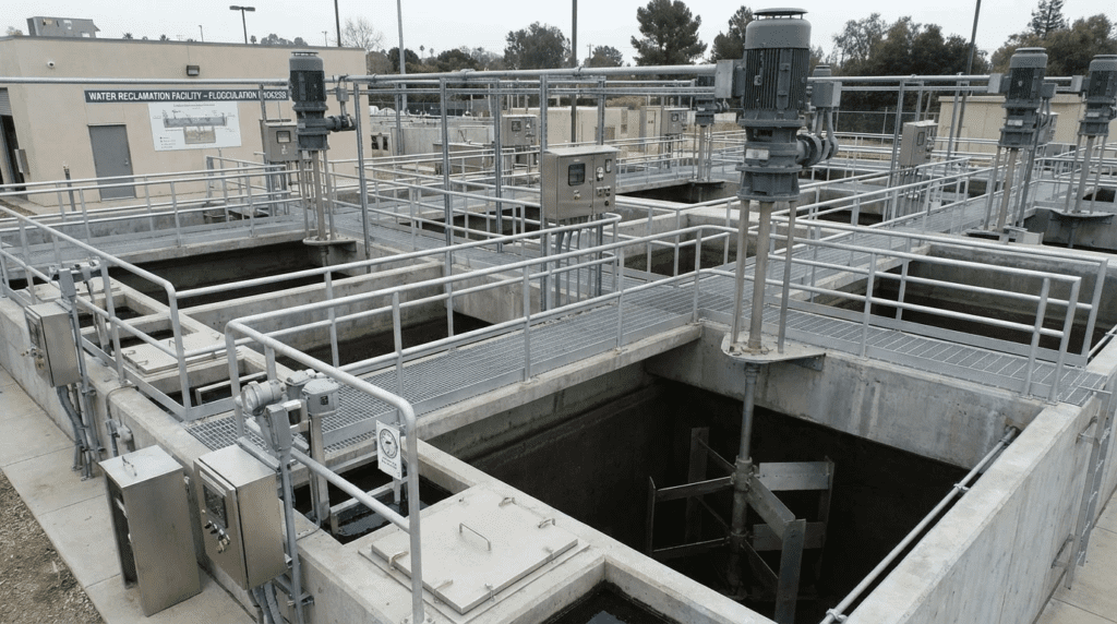
For municipal and industrial treatment plant engineers, the flocculation basin is often where the battle for water quality is won or lost. While the chemical dosing pumps get the attention for precision, the physical flocculators determine whether those chemicals actually perform. Poor mixing energy distribution can raise chemical consumption materially and shorten filter run times. Engineers frequently overlook the nuance of velocity gradient distribution, assuming that any agitator turning at a slow speed will suffice. This oversight leads to floc shear, short-circuiting, and poor settleability in the clarifiers.
Flocculation technology is utilized critically in both potable water treatment, for turbidity and color removal, and wastewater treatment, for chemically enhanced primary treatment or tertiary phosphorus removal. The equipment operates in harsh environments—submerged in corrosive fluids, subjected to variable hydraulic loads, and required to run continuously for decades. The distinction between a specification-compliant unit and a high-performance unit often lies in the mechanical integrity of the gearbox, the hydraulic efficiency of the impeller, and the ease of maintenance for submerged components.
Proper selection requires more than picking a brand; it requires matching the mixing physics to the specific influent characteristics. Equipment selection is one half of the problem, and the chemistry is the other: the coagulation and flocculation process as a whole determines what the mixer is being asked to build, and a flocculator specified without reference to the coagulant program is being sized against an assumption. Consequences of poor choices include energy waste, frequent mechanical seal failures, and accumulation of sludge in dead zones within the basin. This article provides a technical evaluation of the Top 10 Flocculation Manufacturers for Water and Wastewater, outlining how to specify these systems to maximize process reliability and minimize lifecycle costs.
Related Equipment and Chemistry Comparisons
Flocculator selection interacts with two adjacent decisions that are frequently made by different people at different stages of a project: which coagulant and polymer program the plant will run, and what instrumentation will be used to characterize and control the process. Neither is a mixer decision, and both change what the mixer has to do.
Process Equipment and Instrumentation Suppliers
The comparison of Thermo Fisher vs Siemens flocculation equipment addresses the measurement and control side of the flocculation process rather than the agitators themselves. This matters more than it first appears. Flocculation performance is not directly observable in the basin; it is inferred from streaming current, zeta potential, particle counts, turbidity across the process, and jar test results correlated against plant conditions. The instrumentation that produces those measurements determines whether the operator can tune the process at all.
Two considerations dominate this side of the specification. Laboratory capability determines the quality of the jar testing programme that sets the coagulant dose and the target velocity gradients, and a plant without a reliable jar test apparatus and a technician trained on it is running its chemistry on precedent rather than evidence. Process instrumentation capability determines whether those laboratory findings translate into automated control, through streaming current monitors, particle counters, or turbidity profiling upstream and downstream of the flocculation train. Engineers who specify a high-efficiency mixer with variable speed control and no way to measure whether the resulting floc is improving have bought adjustability they cannot use.
Where Chemistry and Equipment Meet
The mixer builds what the chemistry destabilizes. A coagulant program producing a fragile, low-density floc requires gentler tapering and longer detention than one producing a dense, shear-resistant floc, and the choice among available flocculants and coagulants therefore constrains the mixing design rather than following from it. Aluminum and iron salts, prehydrolyzed metal coagulants, and organic polymers each produce floc with different strength and settling characteristics, and a basin designed around one may perform poorly when the plant switches for cost or raw water reasons.
Where floc density is the limiting factor rather than floc size, ballasted processes change the equation entirely. Ballasted flocculation introduces microsand or a similar dense medium as a nucleus, producing floc that settles far faster and permitting dramatically smaller basins and shorter detention times. The mixing requirement shifts accordingly: the process needs enough energy to keep the ballast in suspension and attached, which is a different and generally higher energy duty than conventional flocculation, and the equipment must tolerate an abrasive recirculating medium. Engineers evaluating conventional flocculators for a footprint-constrained site should confirm that the ballasted alternative has been considered and priced before defaulting to a larger conventional basin.
How to Select and Specify Flocculation Equipment
When evaluating the Top 10 Flocculation Manufacturers for Water and Wastewater, engineers must move beyond the catalogue data and interrogate the engineering constraints. The goal is to achieve a uniform velocity gradient without shearing fragile floc particles. The following criteria should form the backbone of any robust technical specification.
Duty Conditions & Operating Envelope
The operating envelope of a flocculator is defined by the process need for tapered flocculation. In a multi-stage basin, the mixing energy must decrease from the first stage to the last to build large, settleable particles.
- G-Value Range: Specifications must define the required velocity gradient G, measured in reciprocal seconds (s−1). Typical ranges start at 60 to 80 s−1 in the first stage and taper down to 10 to 20 s−1 in the final stage.
- Variable Frequency Drives: Fixed-speed flocculators are rarely acceptable in modern design. The equipment must be rated for variable speed turndown, typically on the order of 10:1, to accommodate changing flow rates and temperature-induced viscosity changes.
- Torque Requirements: The motor and gearbox must be sized not just for the impeller’s power draw, but for the starting torque under load, particularly if the basin contains settled solids after a power outage.
Materials & Compatibility
Material selection dictates the lifespan of the wetted parts. Flocculation basins are humid, corrosive environments.
- Shafts and Impellers: Stainless steel (304L or 316L) is standard. For high-chloride environments such as desalination or seawater applications, Duplex 2205 stainless steel is required to prevent stress corrosion cracking.
- Coatings: Carbon steel shafts with epoxy coatings are a lower-cost alternative but present high risks. If the coating is chipped during installation, rapid corrosion will occur.
- FRP (Fiberglass Reinforced Plastic): Some manufacturers offer FRP paddle wheels. While corrosion-resistant, engineers must verify the structural integrity and UV resistance if the basins are uncovered.
Hydraulics & Process Performance
The interaction between the impeller and the fluid is critical. Manufacturers differentiate themselves through impeller efficiency and flow pattern control.
- Tip Speed: To prevent floc shear, tip speeds should generally be limited to 2.0 to 3.0 m/s (roughly 6 to 10 ft/s), depending on floc strength.
- Pumping Capacity: High-flow, low-head impellers such as hydrofoils are preferred over high-shear, radial-flow turbines. The goal is to turn over the tank volume without creating localized high-shear zones.
- Short-Circuiting: The specification must require baffling, whether wall baffles or inter-stage baffles, to prevent the entire fluid mass from rotating with the impeller, which reduces the effective mixing energy.
Installation Environment & Constructability
Physical constraints often drive the selection between vertical and horizontal shaft configurations.
- Vertical Shaft: Motor and gearbox are mounted on a bridge; the impeller is submerged. Preferred for ease of maintenance when designed without a submerged steady bearing.
- Horizontal Paddle Wheel: Classic design for large water treatment plants. Requires through-wall stuffing boxes and submerged bearings, which are maintenance intensive. However, they provide excellent plug-flow characteristics.
- Headroom: For indoor filter galleries, vertical shaft removal height must be calculated. Split-shaft designs may be required.
Reliability, Redundancy & Failure Modes
Flocculators are critical path equipment. If they fail, the sedimentation process fails.
- Gearbox Service Factor: Always specify AGMA service factors. A minimum service factor of 1.5 to 2.0 is recommended for continuous duty to handle shock loads.
- L10 Bearing Life: Specify a minimum L10 bearing life of 100,000 hours for the gearbox and motor bearings.
- Seal Failure: Dry-well construction on gearboxes is preferred to prevent oil leakage down the shaft into the water.
Controls & Automation Interfaces
Modern flocculation requires tight integration with SCADA.
- Torque Monitoring: Higher-specification gearboxes can be equipped with torque sensors to protect against overload and alert operators to process anomalies such as heavy sludge accumulation.
- Speed Feedback: Analog or digital speed feedback allows the SCADA system to verify that the actual mixing intensity matches the setpoint rather than assuming the drive followed its command.
Maintainability, Safety & Access
- Oil Changes: Gearboxes should have oil drain extensions piped to walkway level so operators do not have to lean over open basins.
- Steady Bearings: Avoid submerged steady bearings wherever possible. If shaft length requires stabilization, use a stabilizer ring or hydraulic stabilizer on the impeller rather than a mechanical bearing at the tank floor.
Lifecycle Cost Drivers
- Energy Consumption: Flocculators run continuously. High-efficiency hydrofoil impellers consume substantially less energy than older pitched-blade turbines for the same velocity gradient, because they deliver more pumping per unit of power.
- Chemical Savings: Efficient mixing can reduce coagulant and polymer dosing requirements, and this saving often outweighs the electrical energy saving in total cost of ownership models.
Selection & Specification Framework
The criteria above are individually well established. Poor outcomes generally come from sequencing them badly—most often by selecting equipment on horsepower or capital cost, then computing the velocity gradient afterward to confirm a decision already made.
Step 1: Define the Process Requirement Before the Machine
Establish the required velocity gradient for each stage, the detention time in each stage, and the resulting Camp number for the train as a whole. Specify these as process requirements and let the manufacturer demonstrate how their equipment achieves them. A specification stating horsepower rather than velocity gradient has delegated the process decision to the supplier.
Step 2: Establish the Temperature and Viscosity Range
Velocity gradient depends on viscosity, and viscosity varies significantly with temperature. Cold water is more viscous, so the same power input produces a lower velocity gradient in winter than in summer. Define the design temperature range explicitly and confirm the equipment delivers the required gradient at the cold-water condition, which is the binding case in most northern plants.
Step 3: Worked G-Value and Power Calculation
Consider a three-stage flocculation train treating 8 MGD with a total detention time of 30 minutes, giving roughly 22,300 cubic feet of total basin volume, or about 7,430 cubic feet per stage. Targeting velocity gradients of 70, 40, and 20 s−1 across the three stages, the required power follows from rearranging the Camp-Stein relationship: power equals the square of the velocity gradient multiplied by dynamic viscosity and volume.
At a summer water temperature of 20 degrees Celsius, dynamic viscosity is approximately 2.09 × 10⁻⁵ lb-s/ft2. Stage one therefore requires roughly 702 × 2.09 × 10−5 × 7,430, or about 761 ft-lb/s — approximately 1.4 water horsepower. Stage two at 40 s−1 needs about 0.45 water horsepower, and stage three at 20 s−1 about 0.11. Applying a combined motor and gearbox efficiency near 80 percent and a reasonable margin gives nameplate ratings on the order of 2, 1, and 0.5 horsepower respectively.
Now repeat at a winter temperature of 4 degrees Celsius, where dynamic viscosity rises to roughly 3.23 × 10⁻⁵ lb-s/ft2—about 55 percent higher. Holding the same power input, the achieved velocity gradient falls by roughly 20 percent, so stage one delivers approximately 56 s−1 rather than 70. If 70 s−1 is genuinely required in the cold condition, the equipment must be sized against winter viscosity, raising stage one to roughly 2.2 water horsepower. This is the calculation that distinguishes a train that performs year-round from one that quietly underperforms every winter, and it is routinely skipped.
Step 4: Verify Shaft Mechanics and Critical Speed
Require the first lateral critical speed to be demonstrated at no less than 125 percent of maximum operating speed, with the calculation submitted rather than asserted. Require the shaft deflection at the impeller and the design basis for any stabilization. Long vertical shafts in deep basins are where flocculator mechanical problems concentrate, and the analysis is not visible in a general arrangement drawing.
Step 5: Specify the Tank Internals With the Equipment
Baffling is part of the mixing system, not part of the civil scope to be resolved later. Define wall baffle count, width, and clearance, and define inter-stage baffling that prevents short-circuiting between stages while permitting floc to pass without shear. A high-efficiency mixer in an unbaffled circular basin rotates the water as a body and delivers a fraction of its nominal velocity gradient.
Step 6: Compare on Lifecycle Cost Including Chemical Impact
Build the comparison from installed capital, continuous energy at the actual operating profile, gearbox and seal service intervals, expected shaft and impeller life in the specific water chemistry, and the coagulant dose implication of achieving or missing the design velocity gradient. The last term is usually the largest and almost always omitted, because it sits in the chemical budget rather than the equipment budget.
Comparison of Manufacturers and Technologies
The following tables provide an engineering comparison of the leading market options. Table 1 outlines the specific strengths of manufacturers commonly cited among the Top 10 Flocculation Manufacturers for Water and Wastewater. Table 2 compares the underlying technology types to aid in application selection.
| Manufacturer | Primary Engineering Strengths | Typical Applications | Considerations / Limitations | Maintenance Profile |
|---|---|---|---|---|
| Philadelphia Mixing Solutions | Advanced hydrofoil technology; extensive computational fluid dynamics validation; high-efficiency impellers. | Large water treatment plants, flash mix, flocculation, sludge blending. | Premium pricing; portfolio weighted toward vertical shaft configurations. | Low (robust gearboxes, few submerged parts). |
| SPX FLOW (Lightnin) | Broad impeller catalog; established application engineering; strong drive integration. | Municipal and industrial flocculation, blending, solids suspension. | Catalog breadth requires careful impeller selection rather than default specification. | Low to moderate. |
| WesTech Engineering | Heavy-duty construction; custom solids contact clarifiers; extensive municipal experience. | Flocculating clarifiers, horizontal paddle wheels, vertical mixers. | Often integrated into larger treatment units rather than supplied as standalone mixers. | Moderate (depends on submerged bearing configuration). |
| Evoqua (Xylem) | Diverse portfolio including Envirex legacy designs; varied material options. | Municipal wastewater, retrofits, oxidation ditches. | Large corporate structure can complicate simple spare parts orders. | Moderate to low (standardized industrial components). |
| INVENT Umwelt- und Verfahrenstechnik | Hyperboloid mixing technology; vertical flow mixing; high energy efficiency. | Anoxic zones, flocculation, suspension mixing. | Distinctive flow pattern requires compatible tank geometry; not intended for flash mix. | Very low (no submerged bearings, reliable drive units). |
| Chemineer (NOV) | Industrial-grade gearboxes; high torque capacity; rigid shaft design. | Industrial wastewater, high-viscosity sludge, flash mixing. | Industrial focus may require adaptation for municipal specifications. | Low (heavy duty cycle ratings). |
| Roberts Filter Group | Traditional horizontal paddle wheels; expertise in gravity filtration integration. | Potable water treatment plants using classic flocculation arrangements. | Horizontal designs have submerged bearings requiring seal maintenance. | High (due to submerged seals and bearings). |
| Ovivo | Reactor clarifiers; heavy solids handling; large diameter mechanisms. | Lime softening, flocculating clarifiers. | Specialized for integrated treatment processes. | Moderate. |
| Koflo Corporation | Static mixers; pipe flocculators; no moving parts. | Flash mixing, inline flocculation for small packaged plants. | Head loss penalty; limited turndown and control ability. | Very low mechanically, but requires periodic cleaning. |
| Ekato | Advanced impeller geometries; chemical engineering depth for complex rheology. | Industrial wastewater, non-Newtonian and high-solids fluids. | Frequently more capability than simple municipal flocculation requires. | Low (precision engineering). |
| Technology Type | Fluid Mechanics | Best-Fit Application | Key Constraints | Relative Capital Cost |
|---|---|---|---|---|
| Vertical Hydrofoil | Axial flow; low shear; high pumping rate. | Most modern water and wastewater flocculation basins. | Requires bridge structure; tank depth limits shaft length through critical speed. | Medium |
| Horizontal Paddle Wheel | Approximates plug flow; gentle particle collisions. | Large rectangular potable water basins (legacy design). | High maintenance on submerged seals and bearings; difficult access. | High |
| Hyperboloid Mixer | Radial bottom flow driving vertical circulation. | Deep tanks; suspension mixing; anoxic zones. | Requires specific floor clearance; not suited to heavy scum layers. | Medium-High |
| Walking Beam | Reciprocating vertical motion. | Flocculation where rotating shear is to be avoided entirely. | Mechanical complexity of the linkage; now a niche selection. | High |
| Hydraulic (Baffled) | Serpentine flow converts head loss into mixing energy. | Small systems with steady flow rates. | No adjustability for changing flows; high civil construction cost. | Low equipment / high civil |
| Ballasted (Microsand) | High-energy mixing with a dense nucleating medium. | Footprint-constrained sites; wet weather and peak flow treatment. | Higher mixing energy; abrasive recirculating medium; hydrocyclone and recovery equipment required. | High equipment / low civil |
Engineer & Operator Field Notes
Real-world experience often diverges from the catalogue specifications. The following notes are compiled from field observations regarding flocculation equipment across the manufacturers profiled above.
Commissioning & Acceptance Testing
Commissioning is the first time the theoretical velocity gradient meets reality.
- Runout Check: Do not simply bump the motor. Verify shaft runout is within tolerance, commonly on the order of 0.005 inches per foot of shaft length, before filling the basin.
- VFD Tuning: The drive ramp-up and ramp-down times must be adjusted. Rapid acceleration can shear gearbox keys or twist long shafts because of the inertia of the water. Set ramp times to 30 to 60 seconds as a minimum.
- Power Verification: Measure amp draw at various speeds. If the amp draw is significantly lower than design, the impeller may be undersized, or the fluid is rotating with the mixer, indicating inadequate baffling.
Common Specification Mistakes
Errors at the specification stage often lock utilities into poor equipment.
- Ignoring Critical Speed: Long vertical shafts have a natural frequency. If the operating speed coincides with it, the shaft will oscillate destructively. Specifications must require the first critical speed to be at least 125 percent of maximum operating speed.
- Under-specifying Baffles: Engineers often specify the mixer but omit the tank internals. Without wall baffles, a vertical mixer rotates the water as a body rather than mixing it, drastically reducing the achieved velocity gradient.
- “Or Equal” Traps: Allowing an “or equal” clause without defining strict mechanical minimums such as shaft diameter and gearbox service factor allows contractors to supply undersized, light-duty agitators in place of municipal-grade equipment.
- Specifying Horsepower Instead of Velocity Gradient: A horsepower specification tells the supplier nothing about the process requirement and cannot reject an inefficient impeller that draws the stated power while delivering a fraction of the intended mixing.
O&M Burden & Strategy
Operational strategies should focus on predictive maintenance and on closing the loop between chemistry and mixing.
- Oil Analysis: Perform gearbox oil analysis every 6 months. High metal content indicates gear wear; water indicates seal failure.
- Grease Lines: If the unit has a lower steady bearing, which is best avoided but sometimes unavoidable, ensure automatic lubricators are installed and functioning. Manual greasing of submerged bearings is rarely done on schedule.
- Visual Floc Inspection: Operators should routinely sample floc size at the basin effluent. Pinpoint floc indicates that mixing energy is either too high, causing shear, or too low, providing insufficient collisions. Use the drive to adjust and record the result.
- Close the Loop With Chemistry: Mixer adjustments and coagulant dose changes should not be made independently. A structured approach to coagulation process optimization, combining jar testing against current raw water with systematic velocity gradient adjustment, resolves settleability problems that neither chemistry nor mixing changes alone will fix.
Troubleshooting Guide
- Symptom: Vortexing on the surface.
Root Cause: Insufficient baffling or liquid level too low.
Fix: Install anti-vortex baffles or raise the weir level. - Symptom: Gearbox overheating.
Root Cause: Wrong oil viscosity, overfilled oil, or mechanical overload.
Fix: Check oil level, since excess oil causes churning heat, and verify motor amp draw against the design condition. - Symptom: Poor settleability with turbid supernatant.
Root Cause: Floc shear from excessive tip speed.
Fix: Reduce drive speed. If this causes solids to settle within the flocculation basin, the impeller’s pumping-to-shear ratio is wrong for the application and the hydraulic design needs revisiting. - Symptom: Performance declines seasonally without equipment changes.
Root Cause: Water temperature effect on viscosity, reducing achieved velocity gradient, often compounded by slower reaction kinetics in cold water.
Fix: Increase drive speed within the mechanical limit and revisit coagulant selection for cold-water performance.
Design Details and Calculations
To properly validate submittals from the Top 10 Flocculation Manufacturers for Water and Wastewater, engineers must understand the governing physics.
Sizing Logic: The G-Value
The intensity of mixing is quantified by the velocity gradient G, measured in reciprocal seconds.
G = √(P ÷ (μ × V))
Where P is the power input to the water (watts, or ft-lb/s in customary units), μ is the dynamic viscosity of the water (pascal-seconds, or lb-s/ft2), and V is the volume of the mixing zone (cubic metres or cubic feet). Rearranged for design, the required power is P = G2 × μ × V.
Key Design Steps:
- Determine the water temperature range. Viscosity changes significantly with temperature; cold water is more viscous and requires more power to achieve the same velocity gradient, or delivers a lower gradient at the same power.
- Select velocity gradient values for each stage, for example 70, 40, and 20 s−1 across a three-stage train.
- Calculate the required water horsepower for each stage at the design viscosity.
- Apply efficiency factors. Motor and gearbox inefficiencies mean the nameplate rating must exceed the water horsepower.
- Verify the resulting Camp number for the train and confirm it falls within the target range for the coagulant program in use.
Specification Checklist
- Process Duty: Required velocity gradient per stage at both summer and winter design temperatures, detention time per stage, and target Camp number.
- Motor: TEFC or TENV, premium efficiency, inverter duty per NEMA MG-1 Part 31, Class F insulation, 1.15 service factor.
- Gearbox: Helical or bevel-helical gears with worm gears excluded, minimum AGMA service factor 2.0, dry-well construction, L10 bearing life stated.
- Impeller: Type and blade count, pumping number and power number stated, bolted or keyed attachment, tip speed at maximum operating speed.
- Shaft: Solid shaft preferred over hollow; material and diameter; deflection at the impeller; first lateral critical speed demonstrated at 125 percent of maximum operating speed or better.
- Stabilization: Explicit statement of whether a submerged steady bearing is permitted, and the alternative stabilization method if not.
- Tank Internals: Wall baffle count, width, and clearance; inter-stage baffling arrangement.
- Drive: Turndown ratio, minimum continuous speed, ramp times, and thermal capability at minimum speed.
- Support: Bridge design accounting for torque reaction, dead load, and resonance separation from operating speed.
- Access: Oil drain extension to walkway level, lifting provisions, and shaft removal height clearance.
- Testing: Shop test requirements, field runout verification, dry and wet run vibration baselines.
Standards & Compliance
Flocculation equipment specifications commonly reference Ten States Standards (Recommended Standards for Water Works) for detention time, stage count, and velocity gradient criteria, together with AWWA and AWWA/ASCE water treatment plant design guidance. Gearbox ratings and service factors follow AGMA standards, with the rating basis stated explicitly rather than asserted. Motors follow NEMA MG-1, with Part 31 applicable to inverter-duty machines on variable speed drives. Structural design of bridges and supports follows AISC provisions for steel and ACI 318 where concrete is involved. Guarding of rotating shafts is governed by OSHA 29 CFR 1910.212, and confined space entry for basin maintenance by 29 CFR 1910.146. Wetted components in potable service require certification to NSF/ANSI/CAN 61, with lead content under NSF/ANSI/CAN 372.
Frequently Asked Questions
What is the difference between flash mixing and flocculation?
Flash mixing, or rapid mix, is the high-energy application of coagulant chemicals to raw water to destabilize particles almost instantly. Velocity gradients range from roughly 300 to 1,000 s−1 with retention times of 30 to 60 seconds. Flocculation is the subsequent gentle mixing that agglomerates those destabilized particles into settleable solids, using low velocity gradients of roughly 20 to 70 s−1 and much longer retention times of 20 to 45 minutes.
Why is tapered flocculation important?
Tapered flocculation gradually reduces mixing energy across sequential basins. The first stage uses higher energy to ensure collisions between small particles. As flocs grow they become fragile, so subsequent stages reduce energy to avoid shearing the large flocs already formed. Using the same energy input across all stages typically results in poor settling, because the energy is either too low to build floc initially or too high to preserve it later.
How often should flocculator gearboxes be serviced?
Typical maintenance includes checking oil levels monthly and changing oil every 6 months or roughly 2,500 operating hours, depending on the manufacturer’s manual. Synthetic lubricants may extend this interval to a year. Motor bearing greasing is typically required quarterly. Oil analysis on a six-month cycle is worth more than any of these intervals, because it detects gear wear and seal failure before they produce a breakdown.
What is a typical Camp number?
The Camp number is the product of the velocity gradient and the hydraulic retention time, and it represents the cumulative opportunity for particle collisions. A typical target range for flocculation is roughly 30,000 to 150,000, and the figure is dimensionless. Below the range, floc does not develop adequately; above it, floc that has formed begins to shear. Two trains with the same Camp number can perform very differently if one achieves it through high energy and short time and the other through low energy and long time.
Can I use a vertical mixer in a square tank?
Yes, and square tanks are often favorable, because the corners act as partial baffles and suppress bulk rotation. In circular tanks, full wall baffles are effectively mandatory. Without them the mixer simply spins the water as a body, and the achieved velocity gradient collapses to a small fraction of the calculated value regardless of how efficient the impeller is.
Why avoid submerged bearings?
Submerged steady bearings are among the most common failure points in flocculators. They sit at the bottom of the tank in abrasive sludge, are difficult to inspect, and cannot be serviced without dewatering the basin. If the shaft design is robust enough to operate cantilevered without a bottom bearing, that arrangement is preferable for long-term maintenance reduction, and it is worth accepting a heavier shaft to achieve it.
How does water temperature affect flocculation performance?
Two ways, and they compound. Dynamic viscosity rises as temperature falls, so the same power input produces a lower velocity gradient—roughly 20 percent lower between 20 and 4 degrees Celsius. Separately, coagulation reaction kinetics slow in cold water, so floc formation takes longer even at the correct gradient. Plants that experience seasonal settleability problems are usually seeing both effects at once, and the remedy is a combination of increased drive speed within mechanical limits and a coagulant program suited to cold-water performance.
When does ballasted flocculation make sense instead of conventional?
Ballasted processes earn their added mechanical complexity where footprint or detention time is the binding constraint. By nucleating floc on a dense medium, they achieve settling velocities far above conventional floc and permit much smaller basins and shorter detention. The trade-offs are higher mixing energy, an abrasive recirculating medium requiring hydrocyclone recovery, and greater operational attention. For a constrained retrofit site, or for wet weather treatment where the process runs intermittently at high rate, the comparison frequently favors ballasted; for a greenfield plant with land available and steady flow, conventional usually wins on simplicity.
Conclusion
Key Takeaways
- Specify G, Not Horsepower: State the velocity gradient the process requires and let the manufacturer demonstrate the power needed to achieve it. A horsepower specification cannot reject an inefficient impeller.
- Size Against Winter Viscosity: The same power delivers roughly 20 percent less velocity gradient at 4 degrees Celsius than at 20, and cold water already slows floc formation.
- Eliminate Underwater Bearings: Wherever structurally possible, specify cantilevered shafts to remove the highest maintenance burden in the system.
- Baffles are Part of the Mixer: Never install a vertical mixer without verifying the baffling strategy; an unbaffled basin rotates as a body and delivers a fraction of the calculated gradient.
- Verify Critical Speed: Require the first lateral critical speed to be demonstrated at 125 percent of maximum operating speed, with the calculation submitted.
- Verify Turndown Thermally: Ensure drives and motors are rated for the thermal loads of sustained low-speed operation during low-flow or winter conditions.
- Taper the Energy: Design multi-stage basins with decreasing energy input to build floc initially and preserve it thereafter.
Selecting from the Top 10 Flocculation Manufacturers for Water and Wastewater requires a balanced approach between process hydraulics and mechanical longevity. The ideal system provides the gentle, uniform mixing necessary to build robust floc particles while minimizing the shear forces that would break them apart.
For the engineer, the specification process is the primary tool for risk management. By rigidly defining AGMA service factors, requiring validated flow pattern analysis, and prioritizing maintenance access through features such as dry-well gearboxes, utilities can secure equipment that lasts twenty years or more. Whether choosing a vertical hydrofoil arrangement or a horizontal paddle design, the success of the installation ultimately relies on matching the equipment’s hydraulic profile to the plant’s specific water chemistry, temperature range, and flow variability.