Top 10 GAC Filtration Systems Manufacturers for Water and Wastewater
Introduction
The sudden urgency surrounding PFAS/PFOA compliance, combined with the perennial need for taste, odor, and organics removal, has placed Granular Activated Carbon (GAC) technology at the forefront of utility capital planning. For many consulting engineers and plant directors, the challenge is no longer just selecting a media type, but specifying the mechanical vessel systems that house it. A poorly designed GAC system can result in short-circuiting, impossible maintenance access, and catastrophic head loss issues that media selection cannot solve. When evaluating the Top 10 GAC Filtration Systems Manufacturers for Water and Wastewater, the distinction between a simple steel fabricator and a process-integrated OEM becomes the critical decision point.
GAC filtration systems are deployed widely across municipal drinking water plants for disinfection byproduct (DBP) precursor removal and industrial wastewater facilities for tertiary polishing of recalcitrant organics. While the chemistry of adsorption is complex, the mechanical engineering reality is equally demanding. These vessels often operate at high pressures, require specific lining materials to prevent corrosion from the galvanic coupling of carbon and steel, and necessitate complex underdrain designs to prevent media loss during backwashing.
This article moves beyond marketing brochures to provide a rigorous engineering analysis. We will explore how to specify these systems to ensure constructability and long-term operability. By understanding the capabilities of the Top 10 GAC Filtration Systems Manufacturers for Water and Wastewater, engineers can mitigate risks associated with hydraulic bottlenecks, vessel failure, and excessive lifecycle costs.
How to Select / Specify
Selecting the right GAC system manufacturer requires a multidimensional analysis that goes beyond the initial capital expense. The “system” includes the pressure vessels, internal coating systems, underdrain distribution, backwash supply, and media handling logistics. Below are the critical engineering criteria for specifying equipment from the leading manufacturers.
Duty Conditions & Operating Envelope
The primary driver for GAC system sizing is the Empty Bed Contact Time (EBCT). Unlike rapid sand filtration, where surface loading rate (gpm/sq ft) is the governing parameter, GAC relies on the residence time of water within the media bed to allow adsorption kinetics to occur. Engineers must define:
- Flow Turndown: Systems must maintain uniform distribution at minimum flows to prevent channeling. If the plant operates at variable flow, the underdrain system must be capable of providing adequate distribution pressure drop at low rates.
- Bed Depth & Expansion: Vessels must be tall enough to accommodate deep carbon beds (often 10-12 feet) while providing 30-50% freeboard for bed expansion during backwash. Manufacturers must demonstrate that their vessel geometry allows for this expansion without media loss.
- Pressure Ratings: While gravity contactors are common in large municipal plants, pressure vessels (ASME Section VIII) are standard for retrofit and industrial applications. Specifying the correct Maximum Allowable Working Pressure (MAWP)—typically 50, 75, or 100 psi—is non-negotiable for safety.
Materials & Compatibility
GAC is electrically conductive and sits at the noble end of the galvanic series. When wet carbon contacts carbon steel, it creates a formidable corrosion cell. Specifying the wrong materials leads to rapid vessel failure.
- Internal Linings: For carbon steel vessels, a simple epoxy paint is often insufficient. Engineers should specify high-build, vinyl ester, or glass-flake reinforced linings (minimum 30-40 mils DFT) tested for immersion service and abrasion resistance.
- Stainless Steel Options: For smaller industrial units or highly corrosive wastewater, 304L or 316L stainless steel may be required. However, chloride levels in the feed water must be analyzed to prevent stress corrosion cracking.
- Underdrain Materials: The underdrain encounters the highest mechanical stress during backwash. Polypropylene or stainless steel wedge wire laterals are standard. Avoid PVC in systems subject to water hammer or high temperature fluctuations.
Hydraulics & Process Performance
The hydraulic profile of a GAC system differs significantly from inert media filtration. The irregular shape of GAC granules creates higher friction factors.
- Head Loss: Manufacturers must provide head loss curves based on the specific mesh size (e.g., 8×30 vs. 12×40). Engineers must ensure existing pumps can overcome the “dirty bed” head loss, which can exceed 10-15 psi in pressure systems.
- Underdrain Uniformity: The manufacturer’s underdrain design dictates backwash efficiency. A maldistribution of backwash water leads to “dead zones” where media is never fluidized, creating mudballs and anaerobic conditions.
Installation Environment & Constructability
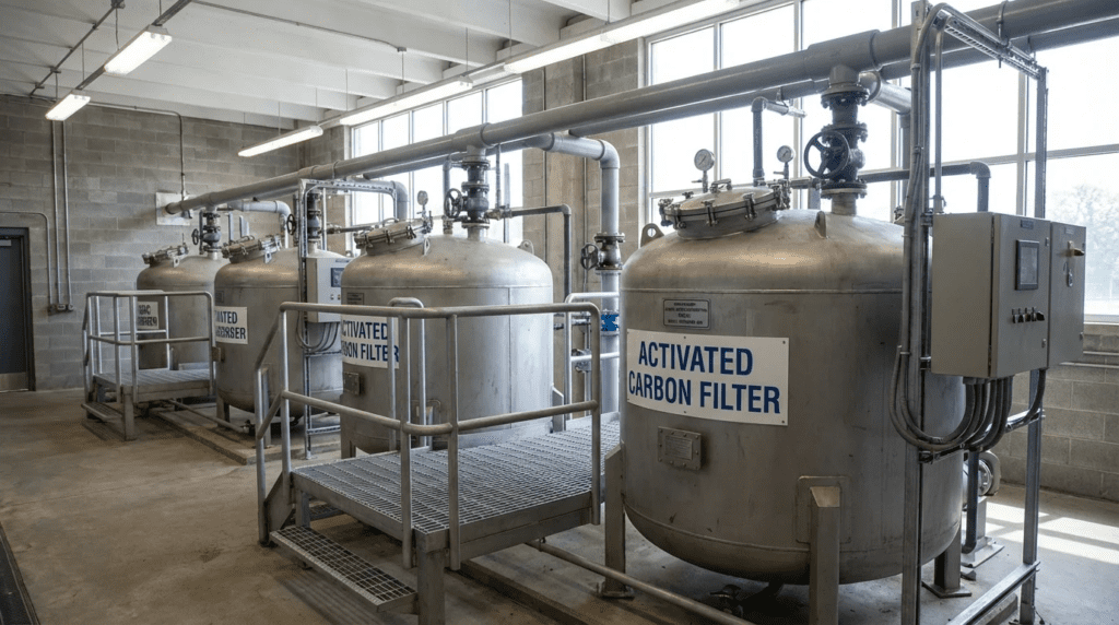
GAC vessels are often massive. A standard 12-foot diameter vessel with a 20,000 lb carbon fill is a significant structural load. The Top 10 GAC Filtration Systems Manufacturers for Water and Wastewater differentiate themselves by offering modular or field-erected options.
- Skid-Mounted vs. Loose: For flows under 1 MGD, skid-mounted systems (vessels + piping + valves pre-assembled) reduce field labor. For larger plants, shipping constraints force loose component delivery.
- Height Restrictions: Indoor retrofits often face ceiling height limits. Engineers must check the “hook height” required for crane installation and the clearance needed for piping headers.
Reliability, Redundancy & Failure Modes
The most common failure mode in GAC systems is underdrain failure (nozzle breakage), leading to media leakage into the effluent.
- Nozzle/Lateral Design: Specify robust attachment methods. Screw-in nozzles should have locking mechanisms. Header-lateral systems must be braced against hydraulic thrust.
- Redundancy: Most GAC systems operate in Lead-Lag configuration. The piping manifold must allow any vessel to be taken offline for media changeout while the others sustain the flow, or bypass capability must be included.
Controls & Automation Interfaces
While GAC is a passive process, its management requires active control.
- Differential Pressure (dP) Monitoring: Essential for triggering backwash sequences.
- Effluent Monitoring: While real-time PFAS/organics sensors are rare, manufacturers should provide sample ports at different bed depths (sample cocks) to allow operators to track the mass transfer zone (MTZ) and predict breakthrough.
Maintainability, Safety & Access
Changing out 20,000 lbs of spent carbon is a major logistical operation.
- Carbon Slurry Lines: Vessels must have dedicated fill and drain lines (usually 2-4 inch camlock fittings) accessible by bulk delivery trucks.
- Manways: ASME code requires manways, but their placement matters. Top manways are needed for inspection; side manways facilitate underdrain repairs.
- Confined Space: Design must account for safe entry protocols, as wet activated carbon removes oxygen from the air, creating an immediate asphyxiation hazard.
Lifecycle Cost Drivers
CAPEX is often 20-30% of the lifecycle cost. The bulk of the cost lies in media replacement.
- Media Volume Efficiency: A poorly designed vessel that short-circuits utilizes only a fraction of the carbon capacity, forcing premature changeouts.
- Backwash Water Waste: Systems requiring excessive backwash volumes drive up OPEX through water loss and waste treatment costs.
Comparison Tables
The following tables provide an engineering comparison of the leading manufacturers and technology configurations. These assessments focus on fabrication capabilities, standard engineering offerings, and typical application fits rather than marketing claims.
Table 1: Top 10 GAC Filtration Systems Manufacturers (System Fabricators)
Note: This list includes major OEMs known for engineering complete GAC vessel systems, not just media suppliers.
| Manufacturer | Primary Engineering Strengths | Typical Applications | Limitations / Considerations |
|---|---|---|---|
| Calgon Carbon (Kuraray) | Vertical integration of media and custom vessel design; extensive mobile/rental fleet; deep bed expertise. | Large municipal drinking water (PFAS), Industrial remediation, Emergency response. | Often prioritize their own media; systems are highly optimized for their specific carbon grades. |
| Evoqua (Xylem) | High-pressure vessel fabrication (ASME); varied underdrain options; massive service network for exchange. | Municipal groundwater, High-purity industrial water, Wastewater polishing. | Standard designs are robust but may be less flexible for highly custom footprint constraints. |
| WesTech Engineering | Heavy custom steel fabrication; gravity contactor designs; integration with other unit processes. | Large-scale municipal gravity filters, Surface water treatment plants. | Focus is primarily on large capital projects; less focused on small, pre-engineered skid systems. |
| Roberts Filter Group | Legacy knowledge in pressure and gravity filtration; custom pressure vessel design; high-spec internals. | Municipal drinking water, specialized industrial filtration. | Primarily a custom engineering shop; longer lead times than “off-the-shelf” skid providers. |
| Leopold (Xylem) | Proprietary underdrain technologies (Type S/X); gravity filter retrofits; air-scour integration. | Municipal gravity GAC contactors, Biological Active Carbon (BAC). | Specializes in concrete gravity basins rather than steel pressure vessels. |
| TIGG (Newterra) | Modular, skid-mounted systems; broad range of lining options; rental and temporary systems. | Remediation, Industrial wastewater, Mid-sized municipal. | Focus on modular/mobile packages may limit options for massive field-erected permanent tanks. |
| Veolia (Suez) | Global process guarantees; integrated treatment trains (RO + GAC); massive scale capabilities. | Complex industrial wastewater, Reuse applications, Desalination post-treatment. | Engineering engagement is typically part of a larger plant-wide scope. |
| Desotec | Mobile filtration services; “Plug-and-play” exchangeable vessels; focus on OPEX reduction via logistics. | Industrial wastewater, Air emissions, Temporary municipal bypass. | Business model relies heavily on their exchange logistics; less focus on permanent, fixed vessel construction. |
| Tonka Water (Kuraray) | Specialized removal applications; custom vessel fabrication; integration with aeration/detention. | Municipal groundwater (Iron/Manganese + Organics), Small to mid-size utilities. | Now integrated with Calgon/Kuraray, streamlining media+system delivery but potentially limiting standalone vessel options. |
| Carbon Activated Corp. | Cost-effective vessel fabrication; large inventory of standard sizes; media supply integration. | General industrial, Municipal retrofit, Groundwater remediation. | Typically focuses on standard pressure vessel configurations rather than complex custom gravity designs. |
Table 2: Application Fit Matrix
Use this matrix to determine which system configuration suits your project constraints.
| Feature / Constraint | Gravity GAC Contactors | Pressure GAC Vessels | Filter-Adsorbers (Sand Replacement) |
|---|---|---|---|
| Typical Flow Range | > 5 MGD (Large Municipal) | 0.1 – 10 MGD (Ind/Muni) | Any (Retrofit existing filters) |
| Head Loss Available | Low Head (Requires pumping to feed) | High Head (Uses line pressure) | Low/Medium Head |
| EBCT Capability | High (10-20 mins typical) | Medium (5-15 mins typical) | Low (Often < 5 mins) |
| Constructability | Concrete Civil Works | Shop Fabricated / Skid | Existing Infrastructure |
| Best For | Greenfield surface water plants, BAC | Groundwater, End-of-pipe wastewater | Taste & Odor seasonal control |
Engineer & Operator Field Notes
Successful GAC implementation relies on more than just buying the tank. The following field notes are compiled from commissioning experiences and operational challenges associated with equipment from the Top 10 GAC Filtration Systems Manufacturers for Water and Wastewater.
Commissioning & Acceptance Testing
The transition from construction to operation is the most critical phase for GAC systems.
- Hydrostatic Testing: Ensure vessels are hydro-tested in accordance with ASME Section VIII (typically 1.3x or 1.5x MAWP) before media loading and lining application (if possible) or carefully inspected after lining.
- Underdrain Levelness: Before media loading, the underdrain floor or nozzle deck must be laser-leveled. Even slight deviations can cause backwash inequality.
- Media Loading & Pre-Wetting: Dry carbon holds significant air. When water is introduced, trapped air can damage the underdrain or cause “air binding,” leading to immediate high head loss. Carbon is typically loaded as a slurry or requires a 24-hour soak period to degas.
- Fines Removal: The initial backwash is critical to remove carbon fines (dust). This water must generally be sent to waste, not the head of the plant, as fines can pass through subsequent filters or foul UV systems.
O&M Burden & Strategy
Granular Activated Carbon is not a “set and forget” technology.
- Backwash Protocol: Unlike sand filters, GAC is not always backwashed based on turbidity breakthrough. It is often backwashed based on time or differential pressure to prevent compaction and biological growth (biofouling), even if the effluent is clear.
- Air Scour Risks: While air scour improves cleaning, it causes abrasion. GAC is softer than sand/anthracite. Aggressive air scour generates fines, resulting in media loss and potential cementing of the bed if fines settle at the bottom. Consult the manufacturer for precise air scour rates (typically 3-5 scfm/sq ft).
- Sample Profiles: Operators should regularly draw samples from the side ports (sample cocks) to test for the contaminant of concern (e.g., TOC, PFAS). This plots the “wavefront” of the contaminant moving through the bed, allowing prediction of changeout months in advance.
Troubleshooting Guide
Symptom: Premature Breakthrough
If the contaminant appears in the effluent long before the calculated bed life:
- Check for channeling (short-circuiting). This often happens if the flow rate is too low to distribute evenly, or if the inlet distributor is damaged.
- Verify the Empty Bed Contact Time (EBCT). Has plant flow increased? Reduced contact time kills adsorption performance.
- Check for pH shifts. Adsorption efficiency for some compounds drops drastically if pH changes.
Symptom: Excessive Head Loss (Clean Bed)
- Check for fines accumulation at the top of the bed (from abrasion) or at the underdrain interface.
- Verify lining integrity. Flaking liner can clog underdrain nozzles.
- Check for biological fouling. If the GAC is acting as a biological contactor unintentionally, biomass may be plugging the void spaces.
Design Details / Calculations
Proper sizing of GAC systems from the top manufacturers requires mastery of specific process calculations.
Sizing Logic & Methodology
The fundamental design equation for GAC contactors is:
EBCT (minutes) = Volume of GAC Media (gallons) / Flow Rate (gpm)
Step-by-Step Sizing:
- Determine Target EBCT: Based on Rapid Small Scale Column Tests (RSSCT) or pilot data. Typical values:
- Taste & Odor: 5-10 minutes
- DBP Precursors: 10-20 minutes
- PFAS: 10-20 minutes (highly dependent on chain length)
- Industrial Organics: 15-45 minutes
- Calculate Media Volume: Using the max flow rate and target EBCT.
- Select Vessel Diameter: Target a hydraulic loading rate (HLR) of 2-10 gpm/ft².
HLR = Flow (gpm) / Cross-Sectional Area (ft²)
High loading rates increase pressure drop; low rates require larger/more vessels. - Check Bed Depth: Ensure the calculated volume fits within a standard straight-side height (typically 10-14 ft) while leaving 40-50% freeboard for expansion.
Specification Checklist
When issuing an RFP for one of the Top 10 GAC Filtration Systems Manufacturers for Water and Wastewater, ensure these items are explicit:
- Code Stamp: ASME Section VIII, Div 1 “U” Stamp (for pressure vessels).
- Lining Spark Test: Require high-voltage holiday testing of internal linings per NACE SP0188.
- Media Transfer: Specify piping materials for carbon slurry lines (usually Schedule 80 PVC or lined steel) and minimum radius bends (long sweep) to prevent erosion.
- Seismic/Wind Load: Tall, slender vessels are susceptible to overturning moments. Specify IBC (International Building Code) seismic parameters.
Standards & Compliance
- AWWA B604: Standard for Granular Activated Carbon (media focus).
- AWWA B100: Standard for Granular Filter Material (includes support gravel).
- NSF/ANSI 61: Drinking Water System Components – Health Effects (Crucial for potable applications).
FAQ Section
What is the difference between adsorption and filtration in GAC systems?
While GAC systems physically filter out suspended solids (filtration), their primary engineering function is adsorption. Adsorption is a chemical/physical process where dissolved organic contaminants adhere to the internal pore structure of the carbon granules. Unlike sand filtration, which only removes particles, GAC removes dissolved compounds like PFAS, pesticides, and taste/odor-causing agents. Over time, the adsorption sites fill up (exhaustion) and the carbon must be replaced or reactivated, even if it still filters particles effectively.
How do I determine the correct EBCT for PFAS removal?
Empty Bed Contact Time (EBCT) for PFAS removal typically ranges from 10 to 20 minutes, but this is a generalization. Short-chain PFAS compounds often require longer contact times than long-chain compounds. The only accurate way to determine EBCT is through Rapid Small Scale Column Testing (RSSCT) or pilot testing using the actual source water. Engineers should never guess this value, as under-sizing the vessel volume will lead to rapid breakthrough and unsustainable operating costs.
Can I retrofit GAC into existing sand filter basins?
Yes, this is known as a “Filter-Adsorber” or “Cap” replacement. However, there are trade-offs. Existing sand filters often have limited depth. Replacing sand with GAC usually results in a very short EBCT (often 2-5 minutes), which is sufficient for seasonal taste and odor control but typically insufficient for DBP precursor or PFAS removal. Additionally, GAC is lighter than sand, so the backwash hydraulics of the existing filter must be evaluated to prevent washing the GAC out of the basin.
What is the typical lifespan of a GAC vessel lining?
A properly applied vinyl ester or glass-flake lining in a GAC vessel should last 15-20 years. However, the abrasive nature of carbon slurry during transfer operations can wear linings down, particularly at inlet/outlet nozzles and lower side-shells. Failures often occur due to “cold wall” effects (blistering) or mechanical damage during maintenance. Routine inspection (spark testing) during media changeouts is recommended to catch pinholes early.
Lead-Lag vs. Parallel Operation: Which is better?
For critical contaminants like PFAS or toxic industrial waste, Lead-Lag (Series) operation is superior. It allows the “Lead” vessel to be fully exhausted (maximizing carbon value) while the “Lag” vessel polishes the effluent, ensuring compliance. When the Lead vessel is spent, it is replaced and becomes the new Lag. Parallel operation is cheaper (lower head loss, fewer pipes) and increases hydraulic capacity, but it risks blending breakthrough water with clean water, potentially violating strict effluent limits.
Conclusion
- Process over Product: Don’t just buy a tank; specify a hydraulic system. The underdrain design and flow distribution are as critical as the media itself.
- Material Compatibility: Wet GAC and carbon steel are a battery. High-spec internal linings (Vinyl Ester/Glass Flake) are mandatory to prevent rapid corrosion.
- Sizing for the Future: Size vessels for the required EBCT (10-20 mins for PFAS) and include freeboard for 30-50% bed expansion. Undersized vessels lead to prohibitive OPEX.
- Logistics Matter: Design the site layout for bulk truck access. If a 40-foot trailer can’t reach the fill pipes, maintenance becomes a nightmare.
- Lead-Lag Security: For strict compliance limits, series operation provides the necessary safety factor against breakthrough.
Selecting from the Top 10 GAC Filtration Systems Manufacturers for Water and Wastewater requires a balanced assessment of mechanical integrity, hydraulic efficiency, and lifecycle support. While manufacturers like Calgon Carbon and Evoqua dominate the market with integrated media-and-vessel solutions, fabricators like WesTech and Roberts Filter offer robust custom engineering for specific plant constraints.
Engineers must move beyond simple flow rate sizing and rigorously calculate EBCT, backwash expansion rates, and head loss profiles. The success of a GAC installation is rarely determined by the adsorption chemistry alone, but by the reliability of the vessel internals, the durability of the corrosion protection, and the ease of media replacement. By utilizing the selection criteria, comparison matrices, and specification checklists provided in this article, utility decision-makers can procure systems that ensure regulatory compliance and operational longevity.