
Top OEMs for Anti-Cavitation Valves
Introduction
In municipal and industrial hydraulic systems, the management of high pressure differentials presents a distinct physical challenge: cavitation. When water accelerates through a valve restriction to the point where the static pressure drops below the fluid’s vapor pressure, vapor bubbles form. As the fluid recovers pressure downstream, these bubbles collapse with violent force, generating micro-jets and shock waves. In standard control valves, this phenomenon leads to severe noise, vibration, choked flow, and rapid erosion of valve internals and downstream piping.
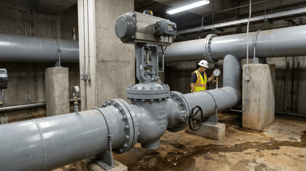
Anti-cavitation valves are engineered specifically to mitigate this destructive process. They are critical components in high-head gravity systems, reservoir fill lines, pressure reducing stations with high reduction ratios, and pump bypass applications. Unlike standard globe valves or butterfly valves, anti-cavitation valves utilize specialized trim designs—cages, slotted sleeves, or stacked plates—to stage the pressure drop or shift the frequency of the turbulence, thereby keeping the fluid pressure above the vapor pressure limit or directing the bubble collapse away from metal surfaces.
Anti-cavitation trim is a severe-service specialty within the much larger family of valves used in water treatment plants, and it is specified only where the hydraulic conditions genuinely demand it. On most of a distribution system, isolation, check, air release, and standard throttling valves handle the duty at a fraction of the cost. Recognizing the narrow band of conditions where anti-cavitation trim is warranted, and correctly identifying them during design rather than after a failure, is the central skill this article addresses.
For consulting engineers, plant managers, and utility directors, the selection of an Original Equipment Manufacturer (OEM) for anti-cavitation valves is not merely a procurement decision; it is a lifecycle reliability calculation. The difference between a properly specified anti-cavitation valve and a standard valve forced into a high-pressure drop application is the difference between a 20-year service life and a catastrophic failure within months.
This article provides a comprehensive, technical analysis of the selection criteria for anti-cavitation valves and evaluates the specific engineering approaches of the four dominant OEMs in this sector: Cla-Val, Bermad, Singer Valve, and OCV Control Valves. The focus is strictly on engineering performance, material science, and operational maintainability.
Subcategory Overview
Anti-cavitation valve work divides into three distinct engineering problems, each with its own failure modes and specification logic. The subsections below outline what each area covers and when an engineer would work from it.
Cavitation and Noise: Causes and Diagnosis
Before trim can be specified, the phenomenon has to be correctly identified, and this is where anti-cavitation valve cavitation and noise analysis begins. Cavitation, flashing, and aerodynamic noise produce different acoustic and vibration signatures, and they call for entirely different remedies: flashing cannot be prevented by staging the pressure drop because the downstream pressure itself sits below vapor pressure, so hardened materials and body geometry become the only defenses. Field diagnosis typically combines sound pressure measurements at the valve and at one and three pipe diameters downstream, accelerometer data on the body, and a review of the operating pressures against the calculated cavitation index. The characteristic signature of full cavitation is broadband noise in the 2 to 8 kHz range accompanied by a distinctive gravel-like rattle, while incipient cavitation is often audible only as an intermittent crackle at specific valve openings. Sound levels above roughly 85 dBA at one meter usually indicate that damage is already occurring, and levels above 90 to 95 dBA correspond to erosion rates that will consume standard trim within a single operating season.
Slurry and High-Solids Service
The small orifices and tortuous paths that make anti-cavitation trim effective are the same features that make it vulnerable to plugging, which is why anti-cavitation valves for slurry service require a fundamentally different approach. Multi-stage cages with drilled holes below roughly 6 mm will blind off in any stream carrying grit, rag, or fibrous material, and once partially blocked the flow redistributes through the remaining passages at velocities well above design, accelerating erosion in exactly the locations the trim was meant to protect. Practical alternatives in solids-bearing service include large-slot single-stage cages, external sleeve or fixed-cone designs that place the restriction outside the solids path, and simply relocating the pressure drop to an open discharge structure where cavitation damage is inconsequential. Where trim must be used, hardened overlays and a strainer or screening step upstream become mandatory rather than optional, and the maintenance interval should be set by inspection rather than by calendar.
Specifying for Wastewater Service
Wastewater applications compress every constraint at once: aggressive water chemistry, hydrogen sulfide exposure, intermittent solids, and limited maintenance access. Guidance on how to specify anti-cavitation valves for these conditions centers on material selection and on writing a specification that survives the substitution process. Body material typically moves from standard ductile iron to fusion-bonded epoxy interior coating or 316 stainless steel cladding, trim moves from 316 stainless to precipitation-hardened grades or Stellite overlay, and elastomers must be confirmed compatible with the actual effluent rather than assumed from a potable water listing. Equally important is stating the performance requirement rather than a part number: specifying the maximum allowable sound pressure level, the required cavitation index margin at minimum, average, and maximum flow, and the acceptable erosion criteria at a defined service interval gives the engineer grounds to reject an inadequate substitution during submittal review.
How to Select This Valve Type
Selecting an anti-cavitation valve requires a more rigorous engineering approach than sizing standard isolation or check valves. The decision matrix must account for fluid dynamics, acoustic properties, and material resistance to erosion. Engineers must move beyond simple Cv calculations and analyze the system’s cavitation index (σ) across the entire flow range.
1. Calculating the Cavitation Index (σ)
The fundamental metric for selection is the dimensionless cavitation index, Sigma (σ). It is defined as the ratio of the potential for resisting cavitation (downstream pressure minus vapor pressure) to the potential for causing cavitation (pressure drop).
Engineers must calculate σ for minimum, average, and maximum flow conditions.
- σ > 2.0: generally indicates benign conditions where standard valves may suffice.
- 1.0 < σ < 2.0: suggests incipient cavitation; standard valves will experience noise and minor vibration.
- σ < 1.0: indicates severe cavitation potential. This is the mandatory zone for specifying anti-cavitation trim.
If the calculated Sigma falls into the critical range, the valve trim must be designed to increase the localized pressure recovery factor (FL) or split the pressure drop into multiple stages.
There is also a lower bound to what trim can accomplish. Where the pressure drop is extreme and continuous, such as a reservoir outlet discharging several hundred feet of head, the more durable answer is often to move the energy dissipation out of the valve entirely. Fixed-cone and sleeve designs discharge into a chamber or to atmosphere where bubble collapse occurs in open water rather than against machined surfaces, and engineers facing this duty should evaluate cone valves alongside multi-stage trim before defaulting to an in-line solution.
2. Valve Function and Trim Design
The core differentiator in anti-cavitation valves is the trim architecture. OEMs employ different strategies to dissipate energy:
- Multi-Stage Trim: This design forces the fluid through a series of restrictions. By breaking a single large pressure drop (ΔP) into two or three smaller drops, the fluid pressure at the vena contracta of each stage remains above the vapor pressure, preventing bubble formation entirely.
- Cage/Sleeve Design: These trims direct opposing flow streams into the center of the valve or through tortuous paths (labyrinths). This increases the friction factor and dissipates energy through turbulence in the center of the fluid stream, rather than against the valve body walls.
- External Impingement: Some designs allow cavitation to occur but focus the bubble collapse in the center of the flow stream, away from the metallic components. This is often less expensive but carries higher risk if flow profiles shift.
3. Materials of Construction
Even with advanced trim designs, high-velocity water can cause erosion. Material selection is critical for the valve body and the trim.
- Body Material: Ductile iron (ASTM A536) is standard for municipal water. However, for severe service, the interior may require epoxy coating or, in extreme cases, 316 Stainless Steel cladding to prevent scour.
- Trim Material: The anti-cavitation trim (seat and cage) must be harder than the standard bronze or brass used in general service valves. Austenitic Stainless Steel (303 or 316) is the baseline requirement. For extreme pressure drops, engineers should specify precipitation-hardened stainless steels (like 17-4 PH) or Stellite overlays to resist work-hardening and pitting.
4. Sizing and Flow Rangeability
A common specification error is “line-sizing” the control valve (e.g., specifying a 12-inch valve for a 12-inch pipe). Anti-cavitation trims significantly reduce the valve’s flow coefficient (Cv) compared to a standard globe valve of the same size due to the restriction of the cage.
Engineers must verify the valve can pass the maximum required flow at the available pressure drop with the restrictive trim installed. Conversely, the valve must be stable at low flows. Anti-cavitation cages can sometimes exhibit “hunting” or instability at very low valve openings (below 10-15%) if the pilot system is not tuned correctly or if the valve is grossly oversized.
5. Pilot Systems and Actuation
Most municipal anti-cavitation valves are hydraulically operated, diaphragm-actuated globe valves controlled by a pilot circuit.
- Pilot Sensitivity: The pilot must be capable of sensing small pressure changes and modulating the main valve smoothly. Jerky movement in an anti-cavitation valve can induce water hammer, exacerbating system stress.
- Filtration: Because anti-cavitation trims often feature small orifices or slots, they are susceptible to clogging if large debris is present. However, the pilot circuit is the most vulnerable point. High-quality strainers on the pilot supply line are mandatory.
6. Lifecycle Cost and Maintenance
The initial capital expenditure (CapEx) for an anti-cavitation valve is typically 2 to 3 times that of a standard control valve. However, the operational expenditure (OpEx) justification is straightforward. A standard valve in a cavitating application may require body replacement or major overhaul every 12 to 24 months. A properly specified anti-cavitation valve should provide 10 to 20 years of service with only elastomeric parts replacement.
Engineers must evaluate the ease of accessing the trim. Can the cage be removed without removing the valve body from the line? Are the seats replaceable or integral?
Comparison Table
The following table contrasts the technical approaches and operational characteristics of the four primary OEMs evaluated in this article. This is not a ranking but a guide to understanding the engineering philosophy and “sweet spot” for each manufacturer. “Trim Technology” refers to the specific mechanism used to dissipate energy. “Serviceability” indicates the complexity involved in inspecting or replacing internal components.
| OEM | Primary Anti-Cavitation Technology | Typical Flow Path | Serviceability Profile | Best-Fit Application Scenarios |
|---|---|---|---|---|
| Cla-Val | KO Trim (Anti-Cavitation) / Disc Stack | Seat-mounted cage with radial slots | High. Trim is a retrofit kit for standard bodies. Easy top-entry access. | Municipal distribution, widely varying flow rates, retrofitting existing standard valves to anti-cav service. |
| Singer Valve | AC Trim (Dual Cage) | Dual sliding cages with impinging flow | Moderate/High. Requires removing the inner valve assembly. Heavy duty construction. | High pressure differential, extreme continuous cavitation, applications requiring precise low-flow stability. |
| Bermad | Double Chamber / V-Port / Cage | Plug and Cage or V-Port Throttling | High. Unitized actuator assembly allows quick removal. | Complex pressure management, fast-response requirements, systems needing independent opening/closing speed control. |
| OCV Control Valves | Series 127 Trim | Slotted or Perforated Cage | High. Simple mechanical design. Standardized parts. | Fuel/Water dual-use environments, industrial process water, standard pressure relief/reduction with moderate cavitation. |
Top OEM Manufacturers
The following analysis details the specific engineering attributes of the four locked OEMs. These manufacturers represent the standard of reliability in the waterworks industry for automatic control valves.
Cla-Val
Overview: Cla-Val is arguably the most ubiquitous name in the North American municipal water market. Their reputation is built on the standardization of the “100-01” Hytrol main valve body, which serves as the platform for nearly all their applications, including anti-cavitation.
Technical Approach:
Cla-Val utilizes the “KO” (Anti-Cavitation) trim. This is not a separate valve body design but rather a specialized seat and disc guide assembly that can often be retrofitted into existing Cla-Val bodies. The KO trim features a 316 Stainless Steel seat with radial slots. As the valve modulates, the disc guide moves within this seat.
The design focuses on directing the energy dissipation. The flow enters the slots and converges in the center of the seat cage. The collision of the flow streams dissipates energy through fluid-to-fluid friction rather than fluid-to-metal friction. This centralization of the turbulence keeps the imploding vapor bubbles away from the metal surfaces of the valve body and the seating surface.
Engineering Strengths:
The primary engineering advantage of the Cla-Val approach is modularity. A utility can convert a standard pressure reducing valve (PRV) into an anti-cavitation PRV simply by changing the internal trim, provided the body size allows for the reduced Cv. The use of 316SS as a standard for the KO trim ensures excellent corrosion and erosion resistance. Additionally, Cla-Val offers “KO-1” and other variations to handle different degrees of cavitation.
Operational Considerations:
Because the trim reduces the effective flow area, engineers must carefully check the valve sizing. A 6-inch valve with KO trim will have significantly less flow capacity than a standard 6-inch valve. In some cases, the valve size must be increased to accommodate the restrictive trim, which involves piping changes.
Bermad
Overview: Bermad is a global leader in hydraulic control valves, known for innovation in actuator design and efficient hydraulic flow paths. In the context of anti-cavitation, Bermad focuses heavily on their 700 and 800 series valves, offering sophisticated cage and plug designs.
Technical Approach:
Bermad employs a “Double Chamber” actuator design in many of their high-performance valves. Unlike a standard single-chamber valve where the closing force is provided by a spring and upstream pressure, the double chamber allows for positive hydraulic pressure to both open and close the valve. This provides extremely precise modulation, which is critical when managing cavitation. If a valve hunts (oscillates), it spends more time in high-wear positions; Bermad’s stable control loop minimizes this.
For the trim, Bermad utilizes stainless steel cavitation cages. These cages are designed with specific slot geometries that increase flow resistance and force energy dissipation within the cage volume.
Engineering Strengths:
The standout feature for engineers is the unitized actuator assembly. The entire internal mechanism can be removed as a single unit for maintenance, which reduces downtime. The Y-pattern body options available in the 700 series also provide higher flow capacities (Cv) for a given valve size compared to standard globe patterns, helping to offset the flow reduction caused by the anti-cavitation cage.
Operational Considerations:
Bermad valves often utilize composite materials in their pilot systems and actuators, which offer excellent corrosion resistance but require operators to be mindful of torque specifications during maintenance to prevent cracking.
Singer Valve
Overview: Now part of Mueller Water Products, Singer Valve has historically maintained a strong niche in high-performance pressure management. They are frequently specified for the most severe cavitation applications where multi-stage energy dissipation is required.
Technical Approach:
Singer’s flagship solution is their Anti-Cavitation (AC) Trim. It utilizes two heavy, sliding stainless steel cages. As the valve opens, the outer cage slides over the inner cage. The holes are aligned such that the flow is directed to impinge upon itself in the center of the cage capsule.
Crucially, Singer focuses on “Low Flow Stability.” Many anti-cavitation valves struggle at low flows because the small opening creates high velocities immediately. Singer’s Single Rolling Diaphragm (SRD) or older Dual Rolling Diaphragm technology ensures smooth, steady movement of the stem even at very low flow rates, preventing the chatter that destroys seats.
Engineering Strengths:
Singer is noted for custom-drilling cages. They analyze the specific hydraulic data (flow vs. head pressure) and can customize the cage perforation pattern to match the system curve. This bespoke engineering prevents “one size fits all” issues. Their trim containment is exceptionally robust, containing the recovery process fully within the stainless steel capsule, ensuring zero damage to the ductile iron body.
Operational Considerations:
The custom nature of some cages means that replacement parts must be ordered by serial number and may have longer lead times than off-the-shelf standard trims. Operators must plan maintenance inventory accordingly.
OCV Control Valves
Overview: OCV Control Valves (an Aquestia brand) is known for rugged simplicity and high reliability in both the waterworks and aviation fueling industries. Their approach to anti-cavitation is consistent with their philosophy of straightforward, maintainable mechanical design.
Technical Approach:
OCV typically utilizes the Series 127 classification for pressure reducing valves, which can be outfitted with anti-cavitation valve trim. Their design generally involves a stainless steel seat and a slotted or perforated stainless steel stem assembly (cage).
The OCV design relies on a straightforward flow-over-the-seat path where the cage restricts the flow exiting the seat ring. This creates the necessary backpressure to keep the fluid in liquid phase or dissipates the energy of bubble collapse within the cage structure.
Engineering Strengths:
Simplicity is the primary strength. The OCV valve has fewer internal moving parts than some dual-chamber competitors. For maintenance crews, this translates to easier troubleshooting and assembly. The guides and seats are designed for alignment, reducing the risk of binding. They are particularly strong in industrial water applications where durability is prioritized over complex feature sets.
Operational Considerations:
While highly effective for moderate to heavy cavitation, extreme, multi-stage pressure drops might require careful consultation with the factory to ensure the standard cage design is sufficient. OCV is excellent at providing clear documentation and support for these specific limitations.
Application Fit Guidance
While all four OEMs produce high-quality equipment, specific nuances make them better suited for certain environments.
Municipal Water Distribution
Cla-Val and Singer Valve are the dominant choices here. Cla-Val is ideal for systems where standardization is key; if a utility already has 500 Cla-Val PRVs, stocking the KO trim kit is a logical logistical decision. Singer is the preferred choice for transmission mains with extreme pressure drops (e.g., bringing water down a mountain into a valley) due to their custom-drilled cage capabilities and low-flow stability.
Municipal Wastewater
Anti-cavitation control valves are generally not recommended for raw sewage due to the small orifices in the cages which will clog instantly. However, for treated effluent or reclaimed water pumping, Bermad and Cla-Val offer robust solutions. Bermad’s obstruction-free flow path (when fully open) and strong actuator forces help manage fluids that may have minor suspended solids, provided the cage design is selected carefully (larger slots vs. small holes).
Industrial Water and High Pressure
OCV Control Valves and Singer Valve excel here. OCV’s background in fuel and industrial handling translates to robust designs that tolerate the rigors of industrial plant cycling. Singer’s ability to handle high ΔP makes them a favorite for cooling tower makeup lines or high-pressure pump bypass systems in power plants.
Buried vs. Exposed Installations
Ideally, no control valve should be buried. They require maintenance. However, if a valve must be installed in a vault or pit that is prone to flooding, Cla-Val and Bermad offer excellent protection. Bermad’s double-chamber actuators are sealed units, and Cla-Val’s pilots are robust against external moisture intrusion, provided the breathers are piped remotely.
Engineer & Operator Considerations
Successful implementation of anti-cavitation valves extends beyond OEM selection. The following best practices are derived from field failures and operational lessons learned.
1. Installation Best Practices
Straight Piping Runs: Anti-cavitation trims require uniform velocity profiles to function correctly. Engineers should specify a minimum of 5 pipe diameters (5D) of straight pipe upstream and 3 to 5 diameters downstream of the valve. Turbulence entering the valve reduces the effectiveness of the cage and can induce vibration.
Air Release Valves: Cavitation, by definition, involves the formation of vapor. Even when controlled, significant pressure drops release entrained air from the water. An air release valve (ARV) must be installed immediately downstream of the anti-cavitation valve to prevent air binding or downstream hammer.
Pro Tip: Record a baseline sound pressure reading at one meter from the valve body, at three defined flow conditions, within the first month of commissioning, and log it in the asset record. Cavitation damage is progressive and nearly silent to a casual listener in its early stages, but the broadband noise level climbs measurably long before the trim fails. A ten-minute annual reading compared against the commissioning baseline turns trim replacement into a planned outage rather than an emergency.
2. Common Specification Mistakes
Oversizing: This is the most common failure mode. An engineer adds a safety factor to the flow, selecting a valve that is too large. The valve then operates at 5-10% open to maintain pressure. In this position, the gap between the plug and the cage is minimal, causing high-velocity wire-drawing (erosion) of the seat. Always size for the actual flow conditions, not the line size.
Ignoring Minimum Flow: Anti-cavitation effectiveness decreases at very low flows because the separation between the cage and the plug may not be engaged. If the system requires prolonged operation at near-zero flow, a smaller bypass valve should be installed to handle the low loads.
Calculating Sigma at One Condition Only: A valve can be comfortably above the cavitation threshold at design flow and deep into the damage zone at night-time minimum flow, when downstream demand collapses and the pressure differential across the valve rises. The index must be evaluated across the full duty envelope, including fire flow and seasonal extremes.
Omitting the Acoustic Criterion: A specification that names a trim type but states no maximum sound pressure level gives the engineer nothing to enforce at submittal. State the limit, the measurement distance, and the flow conditions at which it applies.
Common Mistake: Installing an anti-cavitation valve directly downstream of an elbow or a reducer to save vault space. The distorted velocity profile entering the cage loads one side of the trim far more heavily than the other, producing asymmetric erosion that appears within a year and is frequently misdiagnosed as a manufacturing defect. The five-diameter upstream straight run is not a courtesy dimension; where the vault genuinely cannot accommodate it, a flow conditioner or a larger vault is the correct response, not a shortened approach.
3. Maintenance and Access
Pilot Strainer Maintenance: The pilot system controls the valve. If the pilot strainer clogs, the valve will either fail open or fail closed (depending on the circuit). A flushing schedule for pilot strainers is mandatory.
Exercise the Valve: Valves that sit in one position for months will accumulate mineral scale on the guide stems. When they are finally called to move, they may stick. Operators should exercise these valves (modulate them fully open and closed) at least twice a year to wipe the stems clean and verify diaphragm flexibility.
Spare Parts Strategy: For anti-cavitation valves, the “consumable” is not just the rubber diaphragm. The stainless steel cage and seat are wear parts. While they last much longer than standard trim, they will eventually pit. Utilities should keep a complete “internal kit” (Seat, Cage, Stem, Diaphragm) on the shelf for their critical assets.
Design Details & Standards
Defensible anti-cavitation specifications reference published standards and calculated criteria rather than manufacturer nomenclature. The documents below govern most municipal and industrial applications in this category.
Applicable Standards and References
AWWA C530 — Pilot-Operated Control Valves. The governing standard for the hydraulically operated, diaphragm-actuated valves that carry most municipal anti-cavitation trim.
ANSI/ISA-RP75.23 — Considerations for Evaluating Control Valve Cavitation. Defines the sigma terminology used throughout this article, including incipient, constant, and damage-level cavitation indices, and the scaling relationships between test data and field conditions.
ANSI/ISA-75.01.01 and IEC 60534-2-1 — Flow equations for sizing control valves. Establish the Cv, FL, and choked-flow relationships that anti-cavitation trim modifies.
IEC 60534-8-4 — Prediction of noise generated by hydrodynamic flow. The basis for calculating and specifying acoustic performance in liquid service.
AWWA C512 — Air-Release, Air/Vacuum, and Combination Air Valves. Applies to the downstream air release valve that anti-cavitation installations require.
ASTM A536 — Ductile Iron Castings. The standard body material specification for municipal service.
NSF/ANSI/CAN 61 and NSF/ANSI/CAN 372 — Drinking water system components and lead content. Required for any valve, coating, or elastomer in potable service.
Parameters That Differ by Trim Type
- Pressure recovery factor (FL). Standard globe trim typically falls near 0.85 to 0.90; anti-cavitation cage trim pushes this higher, which is the mechanism by which the onset of choked flow is delayed. Confirm the manufacturer’s tested value rather than a catalog default.
- Flow coefficient penalty. Anti-cavitation trim commonly reduces Cv by 30 to 60 percent relative to standard trim in the same body size. Size the valve from the derated coefficient, not the nominal one.
- Minimum controllable opening. Multi-stage and dual-cage designs are typically stable down to lower openings than single-stage cages, but the manufacturer should state the figure rather than the specifier assuming it.
- Minimum passage dimension. The smallest hole or slot in the cage sets the plugging threshold and should be compared directly against the upstream screening or strainer opening.
- Acceptable sound pressure level. Commonly specified at 85 dBA maximum measured one meter from the valve body and one meter downstream, at stated flow conditions.
Specification Checklist
- Upstream and downstream pressures at minimum, average, maximum, and fire flow conditions.
- Fluid temperature range and corresponding vapor pressure.
- Calculated cavitation index at each flow condition, with the required margin stated.
- Required Cv at maximum flow, calculated with anti-cavitation trim installed.
- Trim architecture: single-stage cage, multi-stage, or dual sliding cage.
- Body material and interior lining or cladding requirement.
- Trim material grade, including any hardfacing or overlay requirement.
- Elastomer compatibility confirmed against the actual fluid, not a generic listing.
- Maximum sound pressure level with measurement location and flow condition.
- Minimum cage passage dimension and the corresponding upstream screening requirement.
- Pilot circuit configuration, strainer, and isolation provisions.
- Upstream and downstream straight pipe run, or flow conditioning where unavailable.
- Downstream air release valve size and location.
- Trim access method: top entry versus full body removal, and required clearances.
- Factory hydrostatic and functional testing, plus field commissioning acceptance criteria.
Frequently Asked Questions
What is the difference between cavitation and flashing?
Both begin the same way, with pressure falling below the fluid’s vapor pressure and vapor bubbles forming at the vena contracta. The difference is what happens downstream. In cavitation, pressure recovers above vapor pressure and the bubbles collapse violently, producing noise and erosion. In flashing, the downstream pressure remains below vapor pressure, so the bubbles persist and a two-phase mixture leaves the valve. This distinction matters because anti-cavitation trim cannot prevent flashing; no amount of staging will raise a downstream pressure that is fundamentally too low. Flashing is managed with hardened materials, expanded outlet geometry, and erosion-tolerant design instead.
At what cavitation index should I specify anti-cavitation trim?
As a working rule, a sigma value below 1.0 mandates anti-cavitation trim, values between 1.0 and 2.0 warrant evaluation for noise and long-term wear, and values above 2.0 generally permit standard trim. These thresholds are approximate and should be checked against the manufacturer’s tested indices for the specific valve, since the actual incipient and damage-level values vary considerably by trim geometry. The index must be calculated across the full flow range rather than at design flow alone, because minimum-flow conditions frequently produce the worst case.
Why does anti-cavitation trim reduce flow capacity so much?
The energy dissipation mechanism is deliberate restriction. Staging a pressure drop across multiple orifices or forcing flow through a tortuous cage path necessarily increases resistance, and resistance is the inverse of flow capacity. A typical anti-cavitation cage reduces the flow coefficient by roughly 30 to 60 percent compared with standard trim in the same body. Engineers must size from the derated coefficient, which sometimes means specifying one or two body sizes larger than the line and accepting the associated reducer and support costs.
Can anti-cavitation valves be used on wastewater?
Not on raw sewage. The cage openings that make the trim effective will blind off almost immediately in a stream carrying rag, grit, or fibrous material, and the resulting flow redistribution accelerates erosion. Treated effluent, reclaimed water, and plant service water are workable provided the cage geometry uses larger slots rather than small drilled holes and upstream screening is in place. Where a significant pressure drop must be taken on a solids-bearing stream, moving the dissipation to an open discharge structure is usually the more durable answer.
How often should anti-cavitation trim be inspected?
An initial internal inspection at 12 to 18 months after commissioning establishes the actual wear rate for the specific installation, after which the interval can be extended, commonly to three to five years for a well-matched application. Annual acoustic readings compared against a commissioning baseline provide a low-cost proxy between internal inspections. Valves operating near the damage-level cavitation index, or those cycling frequently through low openings, warrant the shorter end of every interval.
Is it cheaper to retrofit trim or replace the whole valve?
Where the existing valve is from a manufacturer offering a compatible anti-cavitation trim kit and the body size can accommodate the reduced flow coefficient, retrofitting is typically 30 to 50 percent of the installed cost of a new valve, and it avoids piping modifications entirely. Replacement becomes the better option when the existing body is undersized for the derated capacity, when the body has already sustained erosion damage, or when the required trim architecture is not available for that platform. The sizing check comes first; a retrofit into a body that cannot pass maximum flow simply relocates the problem.
Key Takeaways
- The cavitation index drives the decision, not the valve type — calculate sigma at minimum, average, maximum, and fire flow before selecting any trim, since minimum flow frequently produces the governing case.
- Anti-cavitation trim cannot fix flashing — if downstream pressure sits below vapor pressure, staging the drop achieves nothing and the answer is erosion-tolerant materials and geometry.
- Size from the derated flow coefficient — cage trim typically costs 30 to 60 percent of the standard Cv, and line-sizing the valve is the single most common specification failure.
- Oversizing destroys trim faster than undersizing — a valve held at 5 to 10 percent open wire-draws its seat, so specify for actual duty and add a bypass for sustained low-flow operation.
- State an acoustic limit in the specification — a maximum sound pressure level with a defined measurement location gives the engineer enforceable grounds during submittal review.
- Match the OEM to the duty — Cla-Val for retrofit and fleet standardization, Singer Valve for extreme differentials and custom cage drilling, Bermad for control stability and fast response, OCV for rugged simplicity in industrial service.
Conclusion
The selection of an anti-cavitation valve is a critical engineering task that directly impacts the safety and longevity of water infrastructure. While standard control valves are commodities, anti-cavitation valves are engineered solutions.
Cla-Val offers the security of the industry standard with excellent retrofit capabilities. Singer Valve provides superior technical customization for the most extreme pressure drops and challenging hydraulic profiles. Bermad delivers advanced actuation and control stability for dynamic systems. OCV Control Valves offers rugged, simple reliability for industrial and municipal crossovers.
For the consulting engineer and the plant manager, the goal is to match the valve’s energy dissipation strategy to the system’s calculated Sigma. By prioritizing accurate sizing, appropriate material selection (316SS trims), and a robust maintenance plan, utilities can convert a potential point of failure into a reliable asset that protects the entire piping network for decades.