
Valves for Water & Wastewater Treatment: Types & Selection Guide
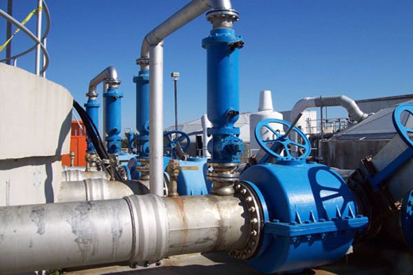
Valves Used in Water Treatment Plants: An In-Depth Analysis
Water is a precious resource, and safe, clean water is vital for both human health and ecological balance. Water treatment plants are essential in ensuring the water supply is suitable for consumption by humans, animals, and plants. At the heart of these facilities are valves — the often underappreciated components that regulate, control, and direct the flow of water through the many stages of treatment. This article seeks to explore the crucial role of valves, the types used in water treatment plants, their functionality, and the considerations for choosing the right valve for specific applications.
Introduction
Water treatment plants are complex systems that involve multiple processes to purify water. These processes include coagulation, sedimentation, filtration, and disinfection. Each of these stages requires precise control of water flow and pressure. Valves are indispensable in these operations, offering control over flow rates, isolating equipment and pipelines for maintenance, and ensuring safe and efficient plant operation.
The Importance of Valves in Water Treatment
Valves in water treatment plants serve several critical functions:
- Flow Control: Regulate the rate of water flow to ensure proper treatment and prevent system overload or damage.
- Isolation: Enable plant operators to shut off sections of the facility for maintenance or emergencies without disrupting the entire plant’s operation.
- Pressure Regulation: Protect sensitive equipment by modulating pressure levels within the plant’s system.
- Backflow Prevention: Prevent contamination by ensuring that water only flows in the intended direction.
Given these roles, the choice of valves directly impacts a water treatment plant’s efficiency, safety, and reliability.
A water or wastewater facility typically contains more valves than any other class of equipment, and the great majority of them are doing one of three jobs: opening and closing a flow path, modulating it against a setpoint, or protecting the system from something it should not experience. This guide serves as the master reference for valve practice across water and wastewater treatment, and the Subcategory Overview below maps each valve family to its dedicated resource.
Subcategory Overview: The Valve Landscape
Valves divide by what they are asked to do rather than by how they look. Isolation valves open and close; regulating valves hold a variable at a setpoint; protection valves act automatically when a condition arises; specialty valves handle duties peculiar to water systems; and actuation determines how any of them is driven. The sections below follow that division.
General Valve Practice
Wastewater Treatment Valves
Wastewater treatment valves face conditions that clean water valves do not: solids, rags, grit, corrosive sewer atmospheres, and intermittent service that leaves a valve unexercised for months before it is needed urgently. That combination rules out designs with cavities or tight clearances where material can pack, which is why full-port and resilient-seated configurations dominate on the wastewater side. Material selection also shifts, with elastomers and coatings chosen against hydrogen sulfide exposure rather than against potable water requirements. Comparative understanding across the full valve set is the fastest route from a duty description to a shortlist worth pricing.
Isolation Valves
Isolation duty means fully open or fully closed, with the valve spending nearly all its life in one position and being judged on whether it seals when called upon.
Gate Valves
Gate valves raise and lower a wedge or parallel disc perpendicular to flow, giving a full-bore opening with almost no pressure loss when open. Resilient-seated designs have largely displaced metal-seated gate valves in water service because the encapsulated rubber wedge seals against a smooth flat-bottom body with no seat groove to collect grit. They are unsuitable for throttling, where partial opening causes seat erosion and vibration. Multi-turn operation makes them slow to close, which is often an advantage for surge control on long transmission mains.
Butterfly Valves
Butterfly valves rotate a disc on a shaft through the flow path, achieving isolation in a fraction of the face-to-face length and weight of a gate valve of equal diameter. That compactness makes them the default for large-diameter service where a gate valve would be impractical to install or support. The disc remains in the flow stream when open, so pressure loss is higher than a full-bore valve and the disc is exposed to debris. Their quarter-turn action is fast, which makes closure timing a genuine surge consideration on long lines.
Ball Valves
Ball valves rotate a bored sphere between seats, giving tight bidirectional shutoff and a full-bore opening in the same quarter-turn package. They are the standard choice for small-diameter isolation, chemical feed lines, and any duty where positive shutoff matters more than modulation. Double block and bleed configurations provide two seating surfaces with a vented cavity between them, allowing downstream work to proceed with verified isolation. Seat material governs the temperature and chemical envelope, and throttling degrades seats quickly.
Plug Valves
Plug valves rotate a tapered or cylindrical plug through a quarter turn, and the eccentric variant lifts the plug away from the seat as it opens so that the sealing surfaces never rub against grit-laden flow. That single feature makes eccentric plug valves the workhorse of sludge, scum, and raw wastewater isolation, where a ball or gate valve would abrade quickly. They also throttle better than most quarter-turn valves. Higher operating torque than an equivalent ball valve is the trade-off, which affects actuator sizing.
Cone Valves
Cone valves use a rotating conical plug with a full-bore passage, giving very low headloss and clean shutoff in a design that lifts its sealing surfaces clear during rotation. They are applied where both tight isolation and minimal flow disturbance are required, including pump discharge and high-head service, and their smooth passage suits fluids carrying solids. The design is mechanically more involved and correspondingly more expensive than a butterfly or plug valve, so it is specified where the hydraulic or sealing requirement justifies it rather than as a general-purpose choice.
Gates
Gates, meaning slide gates, sluice gates, weir gates, and stop gates rather than gate valves, control open-channel flow in headworks, basins, and channels rather than flow in a closed pipe. Slide gates isolate channels and basins for maintenance; weir gates adjust an overflow elevation to divide flow between parallel trains; flap gates prevent backflow into an outfall. Seal design and leakage class matter because a gate that will not seal cannot dewater the structure behind it, and frame stiffness under seating and unseating head governs whether the seal holds in practice.
Regulating and Control Valves
Regulating duty means holding a variable at a setpoint, which places the valve permanently in a partially open position and makes its flow characteristic, cavitation behaviour, and control resolution the governing concerns.
Globe Valves
Globe valves move a plug perpendicularly onto a seat, forcing flow through a tortuous path that produces high pressure loss when open but excellent throttling control. The plug and seat geometry can be shaped to give linear, equal-percentage, or quick-opening characteristics, which is why globe bodies remain the standard for modulating service where control quality matters more than headloss. The angle-pattern variant turns the flow ninety degrees within the body, reducing the number of fittings and improving performance in erosive or flashing service. High operating force and pressure drop are the costs.
Control Valves
Control valves are defined by function rather than by body style, and the family covers globe, ball, butterfly, and specialty bodies fitted with positioners and trim selected for modulating duty. Sizing follows from the flow coefficient Cv required across the operating range rather than from line size, and a control valve sized to line diameter is almost always oversized, spending its life near the closed position where control resolution is poorest. Inherent flow characteristic, rangeability, and cavitation index at the worst operating point are the parameters that matter. A dedicated resource on control valve sizing and selection is in preparation.
Diaphragm Valves
Diaphragm valves use a flexible membrane pressed onto a weir or straight-through body to close the flow path, isolating the operating mechanism completely from the fluid. That separation is the design’s defining advantage: no stem packing to leak, no cavities for fluid to sit in, and full compatibility with aggressive chemicals through liner and diaphragm material selection. They are widely used in chemical feed and sampling service for exactly those reasons. Pressure and temperature limits are modest, and the diaphragm is a wear item with a defined replacement interval.
Pinch Valves
Pinch valves close by squeezing a flexible elastomeric sleeve, so the only wetted part is the sleeve itself and the flow path is a smooth full bore when open. That makes them well suited to abrasive slurries, lime, carbon, and other fluids that would destroy a conventional seat, and they pass solids without the cavities where material would otherwise pack. Throttling is possible but the characteristic is nonlinear. The sleeve is consumable, and its life depends on the abrasiveness of the service and the frequency of cycling.
Solenoid Valves
Solenoid valves use an electromagnetic coil to actuate a small valve directly, giving fast, simple on-off control for chemical feed, instrument air, sampling, and utility water. Direct-acting designs open against system pressure using coil force alone and are limited to small orifices; pilot-operated designs use line pressure to do the work, which allows much larger passages from the same coil but requires a minimum differential pressure to function. That minimum differential is the specification detail most often missed, and a pilot-operated valve installed where differential can approach zero will fail to open.
Automatic Valves
Automatic valves operate without external power or a control signal, using line pressure acting on a diaphragm or piston to hold a setpoint. Pressure reducing, pressure sustaining, flow control, and level control functions are all achieved by varying the pilot arrangement on what is otherwise a common hydraulically operated body. Because they need no electricity and no instrumentation, they are the standard solution in distribution systems and remote sites where power is unavailable. Pilot tubing and strainer maintenance is the recurring service item. A dedicated resource on automatic valve actuation options is in preparation.
Check and Protection Valves
These valves act on the condition of the system rather than on a command, which means their failure is usually discovered only when the event they were meant to handle occurs.
Check Valves
Check valves permit flow in one direction and close when it reverses, protecting pumps from backspin and preventing contamination through backflow. Swing, dual plate, tilting disc, silent, and ball designs differ chiefly in how quickly they close, and closure speed is the specification that matters most: a check valve that slams shut after flow reversal has begun generates the surge it was meant to prevent. Dual plate designs close faster than swing checks in a shorter face-to-face length. Sizing on line diameter rather than on velocity leaves the disc fluttering at partial flow, which destroys hinge pins.
Pressure Relief Valves
Pressure relief valves open at a preset pressure to protect piping, vessels, and equipment from overpressure, and on any positive displacement pump installation they are a safety requirement rather than an option. Set pressure, relieving capacity at the accumulated pressure, and the discharge routing all form part of the specification, and a relief valve discharging to an inadequate destination has moved the hazard rather than removed it. Periodic testing is necessary because these valves sit unused for long periods and can seize.
Air Valves
Air valves manage air in pipelines, and the distinction between their three types is frequently confused. Air release valves vent small accumulations of air continuously during operation through a small orifice; air and vacuum valves handle large volumes during filling and draining through a large orifice but close once the line is pressurized; combination valves do both. Placement at high points and along descending grades determines whether they work at all. Omitting them causes air pockets that restrict capacity, and omitting vacuum protection risks pipeline collapse during drainage.
Anti-Cavitation Valves
Anti-cavitation valves address the damage that occurs when pressure at the vena contracta falls below vapour pressure and the resulting bubbles collapse violently against trim and body. Multi-stage trim takes the pressure drop in a series of smaller steps, keeping local pressure above vapour pressure throughout, while other designs distribute the drop across many small passages. These are specified where the cavitation index at the worst operating condition falls below the threshold for the base valve, most commonly on high-head throttling and pressure reduction duties. They cost considerably more than conventional trim, so the cavitation calculation should justify them rather than habit.
Water-Specific and Specialty Valves
Altitude Valves
Altitude valves control reservoir and storage tank level automatically using line pressure and a pilot sensing the tank level, closing as the tank fills and reopening as it draws down without any electrical input. Single-acting versions permit inflow only and require a separate outflow path; double-acting versions allow the tank to feed back into the system when demand exceeds supply. They are among the most common causes of unexplained tank level behaviour in distribution systems, since a pilot fouled by sediment or a leaking sensing line produces symptoms that look like a control or telemetry problem.
Mud Valves
Mud valves are heavy-duty sludge drain valves mounted flush in the floor or wall of a clarifier, digester, or basin, with a rising stem operated from a handwheel or actuator on the operating floor above. The flush mounting is the point of the design, since a valve protruding into the hopper would collect solids and defeat the drainage it exists to provide. Seat and disc materials are selected for abrasion resistance, and stem length and guide arrangement must suit the basin depth. A dedicated resource on mud valve actuation options is in preparation.
Sleeve Valves
Sleeve valves dissipate energy by passing flow through many small orifices in a cylindrical sleeve, distributing the pressure drop over a large area rather than concentrating it at a single restriction. That distribution is what allows them to handle very high differential pressure without cavitation damage, which makes them the standard solution for reservoir outlet and pressure-reduction service where a conventional throttling valve would be destroyed. They are usually submerged or discharge into a chamber, and their cost reflects their specialized construction. A dedicated resource on sleeve valve actuation options is in preparation.
Hydrant Equipment
Hydrant equipment covers fire hydrants themselves along with the auxiliary valves, flushing devices, and diffusers used for distribution system maintenance. Automatic flushing devices maintain water quality in low-turnover areas of a network by discharging on a schedule, addressing disinfectant residual loss and nitrification in dead ends without operator attendance. Diffusers and dechlorination attachments allow flushing without discharging chlorinated water to the environment. A dedicated resource on hydrant flusher sizing and selection is in preparation.
Actuation and Automation
Actuators
Actuators convert an electrical, pneumatic, or hydraulic signal into the torque or thrust that moves a valve, and the actuator is more often the source of a valve problem than the valve body is. Electric actuators offer precise positioning and integrate readily with plant control systems but require power at the valve; pneumatic actuators are fast, tolerate hazardous areas, and fail predictably on air loss, at the cost of a compressed air system; hydraulic actuators deliver the highest force in the smallest package for large valves. Torque must be specified against the worst case including unseating and differential pressure, with a margin, and fail position on power or signal loss should be a deliberate decision rather than a default.
Types of Valves Used in Water Treatment Plants
Several types of valves are utilized in water treatment facilities, each chosen based on its functionality, durability, and suitability for specific tasks.
1. Gate Valves
Description:
Gate valves are among the most commonly used valves in water treatment operations. They feature a gate-like disc that moves perpendicularly to the flow path, offering minimal resistance when fully open.
Functionality:
- Shut-off: Primarily used for on/off service. Gate valves are not suitable for flow regulation because they are either fully open or fully closed to minimize seat and disk wear.
- Isolation: Ideal for isolating pipeline sections, particularly when full bore flow is required.
Advantages:
- Low pressure drop when fully open.
- Cost-effective and simple design.
- Suitable for large diameter pipes.
Disadvantages:
- Not suitable for throttling applications.
- Slow operation due to multiple turns required to open or close the gate.
2. Ball Valves
Description:
Ball valves use a spherical disc to control the flow. They offer a reliable shut-off mechanism with a fast quarter-turn operation.
Functionality:
- Isolation and Control: Provide secure isolation of equipment and can also be used for flow control in some low-precision applications.
Advantages:
- Quick operation (90-degree turn).
- Tight sealing with less torque.
- Durable and require less maintenance.
Disadvantages:
- Not ideal for throttling applications due to potential damage to the seats.
3. Butterfly Valves
Description:
Butterfly valves have a disk rotated on a diametric axis inside a pipe. They are used for isolating or regulating flow.
Functionality:
- Flow Regulation and Isolation: Suitable for both functions, making them versatile.
- Space Efficiency: Their compact design makes them ideal for applications with limited space.
Advantages:
- Lightweight and cost-effective.
- Fast operation (90-degree turn).
- Available in large sizes.
Disadvantages:
- Not suitable for high-pressure applications.
- Can cause flow turbulence when partially open.
4. Check Valves
Description:
Check valves allow fluid to flow in one direction only, preventing backflow and potential contamination of the clean water supply.
Functionality:
- Backflow Prevention: Essential for ensuring process integrity and compliance with health standards.
Advantages:
- Simple and automatic operation.
- Low cost and compact design.
- Critical for safety in preventing reverse flow.
Disadvantages:
- Potential for water hammer if not properly sized and selected.
- Requires regular maintenance to ensure efficiency.
5. Diaphragm Valves
Description:
Diaphragm valves use a “diaphragm” to regulate flow. They are particularly suited for applications requiring sanitary conditions.
Functionality:
- Flow Control and Isolation: They offer excellent control of flow rates and provide isolation in clean processes.
Advantages:
- Ideal for corrosive and viscous fluids.
- Simple, clean design with no pockets to trap fluids.
- Excellent sealing capabilities.
Disadvantages:
- Limited pressure and temperature range.
- Not suitable for high-flow applications.
6. Control Valves
Description:
Control valves are specialized valves designed to modulate flow and pressure based on process variables.
Functionality:
- Precision Flow Regulation: Essential for maintaining the precise control required in sensitive stages of water treatment.
Advantages:
- High level of control and accuracy.
- Can be automated and integrated with control systems.
- Suitable for a range of pressures and temperatures.
Disadvantages:
- Higher cost and complexity.
- Requires regular calibration and maintenance.
Selection and Specification Framework
Valve selection is a sequence of eliminations rather than a single choice. Each step below removes options that cannot serve the duty, and what survives is a shortlist worth pricing.
Step 1: Define the Duty Before the Valve Type
Start with what the valve must do, not what it will be. Isolation duty means fully open or fully closed with tight shutoff when called upon, and the valve will spend years in one position. Modulating duty means the valve sits partially open indefinitely, holding a variable against a setpoint, and control resolution and cavitation behaviour become governing. Protection duty means the valve acts automatically on a condition, and its response speed matters more than its steady-state performance. A valve specified for the wrong duty class will disappoint regardless of how well it is made.
Step 2: Characterize the Fluid
Fluid character eliminates entire families. Clean finished water accommodates almost anything. Raw wastewater with rags and grit rules out designs where the seat rubs through the flow path, which is why eccentric plug and resilient-seated valves dominate there. Thickened sludge and abrasive slurries favour pinch and knife gate designs with full-bore passages and no cavities. Aggressive chemicals push toward diaphragm and lined constructions where no metal contacts the fluid. Elastomer and coating selection then follows from the same characterization, with hydrogen sulfide exposure being the specific concern on the wastewater side.
Step 3: Size on Cv and Velocity, Not on Line Diameter
The most common and most expensive valve specification error is sizing a modulating valve to match the pipe. A worked example shows why.
Velocity check: A 24-inch pipe has a cross-sectional area of about 3.14 ft². At 8,000 gpm, or 17.83 cfs, velocity is 17.83 ÷ 3.14 ≈ 5.7 ft/s — comfortably within the 3 to 8 ft/s range typical for transmission service.
Isolation valve Cv: With an allowable pressure drop of 3 psi fully open, required Cv is Q × √(SG ÷ ΔP) = 8,000 × √(1 ÷ 3) ≈ 4,619. A 24-inch butterfly valve comfortably exceeds this, so the valve is not the constraint at full open.
Cavitation check, isolation duty: The cavitation index σ = (P₁ − Pv) ÷ ΔP. With P₁ = 59.7 psia and vapour pressure 0.34 psia, σ = 59.36 ÷ 3 ≈ 19.8. No cavitation concern.
Now the modulating case: Suppose the same line must be throttled to 2,000 gpm, taking a 35 psi drop. Required Cv falls to 2,000 × √(1 ÷ 35) ≈ 338 — about seven percent of the isolation valve’s capacity. A line-size valve asked to do this sits nearly closed, where its flow characteristic is steepest and its control resolution is worst.
And the cavitation index collapses: σ = 59.36 ÷ 35 ≈ 1.7, which is in the range where many valve trims cavitate. That single number is what drives the decision toward a smaller control valve, anti-cavitation trim, or staged pressure reduction.
The lesson holds generally: an isolation valve is sized to the line, a control valve is sized to the required Cv range, and the two are almost never the same diameter.
Step 4: Check the Surge Consequence of Closure
Valve closure time is a system design parameter, not an operating convenience. The instantaneous surge head from stopping a flowing column is ΔH = a × ΔV ÷ g, where a is the pressure wave speed. Continuing the example above, with a wave speed near 3,500 ft/s in ductile iron pipe and a velocity change of 5.7 ft/s, instantaneous closure would generate roughly 617 ft of surge head, or about 267 psi — several times the operating pressure and enough to rupture the line.
The controlling figure is the critical time 2L ÷ a. On a 5,000 ft line at that wave speed, that is about 2.9 seconds; closure slower than the critical time reduces the surge proportionally, closure faster than it does not. This is why quarter-turn valves on long transmission mains need actuator speed control or a gate valve instead, and why check valve closure characteristics matter so much.
Step 5: Specify the Actuator to the Worst Case
Actuator torque must cover the highest requirement the valve will see, which is usually unseating against full differential pressure rather than running torque, with a margin above that. Fail position on loss of power or signal should be an explicit decision: fail open, fail closed, or fail in place each carry different consequences, and the right answer depends on what the valve protects. Manual override, position indication, and torque limit settings belong in the specification rather than being left to the supplier’s standard.
Step 6: Design for Access and Exercise
A valve that cannot be reached will not be maintained, and a valve that is never operated will not work when needed. Buried valves need boxes located and recorded; valves in vaults need clearance for stem removal; large valves need lifting provision. Exercise programs matter particularly for isolation valves that sit unmoved for years, since corrosion and deposit accumulation will seize a valve that is otherwise sound. Utilities that discover during an emergency that a critical isolation valve will not close usually find the valve was never exercised rather than that it failed.
Valve Selection Comparison
| Valve Type | Primary Duty | Action | Flow Path | Best-Fit Application | Key Limitation |
|---|---|---|---|---|---|
| Gate | Isolation | Multi-turn | Full bore | Buried mains, pipeline isolation | Cannot throttle, slow to operate |
| Butterfly | Isolation, coarse regulation | Quarter-turn | Disc in flow | Large diameter, space-constrained | Headloss, fast closure surge risk |
| Ball | Isolation | Quarter-turn | Full bore | Small diameter, chemical feed | Seat damage if throttled |
| Eccentric Plug | Isolation, throttling | Quarter-turn | Near full bore | Sludge, scum, raw wastewater | Higher torque, larger actuator |
| Cone | Isolation | Quarter-turn | Full bore | High head, low headloss required | Cost and mechanical complexity |
| Globe | Modulating | Multi-turn | Tortuous | Precise throttling and control | High pressure loss and force |
| Diaphragm | Modulating, isolation | Multi-turn | Weir or straight | Chemical feed, sampling | Pressure and temperature limits |
| Pinch | Modulating, isolation | Linear | Full bore sleeve | Abrasive slurries, lime, carbon | Sleeve is consumable |
| Check | Protection | Automatic | Varies by design | Pump discharge, backflow prevention | Slam and surge if wrongly selected |
| Pressure Relief | Protection | Automatic | Normally closed | PD pump discharge, vessel protection | Can seize if never tested |
| Air Valve | Protection | Automatic | Vent orifice | Pipeline high points, filling and draining | Placement determines effectiveness |
| Sleeve | Energy dissipation | Linear | Multi-orifice | High differential pressure reduction | Specialized, high cost |
| Actuation | Strength | Fail Behaviour | Best-Fit Situation | Principal Requirement |
|---|---|---|---|---|
| Manual | Simple, no utilities required | Stays in position | Infrequent isolation, accessible location | Access and an exercise program |
| Electric | Precise positioning, easy integration | Typically stays in place | Modulating duty tied to plant controls | Power at the valve, area classification |
| Pneumatic | Fast, safe in classified areas | Spring return to a defined position | Frequent cycling, fail-safe required | Reliable instrument air supply |
| Hydraulic | Highest force in smallest package | Configurable | Very large valves, high differential | Hydraulic power unit and containment |
| Self-operated | Needs no external power at all | Holds setpoint by line pressure | Remote sites, distribution systems | Pilot and strainer maintenance |
Factors to Consider When Selecting Valves
Choosing the right valve involves balancing various factors such as cost, durability, application requirements, and environmental conditions. Key considerations include:
Material Compatibility
- Corrosion Resistance: Water treatment environments often expose valves to corrosive substances. Selecting valves made of corrosion-resistant materials like stainless steel, PVC, or bronze is crucial.
- Temperature and Pressure Tolerance: The valve material should be appropriate for temperature and pressure conditions specific to the application.
Operational Needs
- Flow Characteristics: Different processes demand varying flow rates. Valves must be selected to match these operational requirements.
- Frequency of Operation: Valves operated frequently should be easy to use, such as those with a lever handle, for quick cycles.
Maintenance and Longevity
- Ease of Maintenance: Valves that require frequent cleaning or volatile parts should offer easy access for maintenance.
- Lifespan and Reliability: A valve that fails can disrupt operations and lead to significant costs. Thus, choosing reliable valves with a higher lifespan is important.
Automation and Control
- Integration with Systems: In modern water treatment plants, valves are often part of automated systems. Compatibility with actuators and control systems is essential for enhanced efficiency and process control.
Environmental Considerations
- Compliance with Regulations: Valves in water treatment must comply with industry regulations to ensure safety and efficiency.
- Impact on Energy Consumption: Valves that facilitate efficient system operation (e.g., reduced pressure drops) can contribute to energy savings.
Field Notes
The observations below recur across valve installations regardless of type.
Commissioning Considerations
Stroke every valve through its full travel before the system is pressurized, and record the actual time taken rather than accepting the nameplate figure, because closure time is a surge parameter and the installed speed frequently differs from the specified one. Torque limit and end-of-travel settings on electric actuators should be verified under real differential pressure rather than in a dry stroke, since a valve that seats correctly against no pressure may stall against full head. Position indication should be confirmed against actual valve position, as reversed or mis-scaled feedback is common and is discovered later at the worst moment. Buried valve locations should be surveyed and recorded at installation, since finding them afterward is far harder than recording them once.
Common Specification Mistakes
Several errors appear repeatedly. Control valves are sized to line diameter, leaving them operating near the closed position where control is poorest and cavitation worst. Check valves are selected on size and pressure rating without regard to closure characteristics, producing slam on pump trip. Quarter-turn valves are specified on long transmission mains without closure speed control, creating a surge hazard that the actuator can deliver in under a second. Actuator torque is specified against running torque rather than unseating torque at full differential. Air valve placement is treated as a detail rather than a hydraulic calculation, so high points go unvented. Materials are selected for the average condition rather than for the cleaning chemistry or the sewer atmosphere the valve actually sits in.
Pro Tip
Run a valve exercise program on a fixed schedule and record the results, particularly for isolation valves that never move in normal operation. The failure mode that hurts most is discovering during a main break or an equipment emergency that the isolation valve which should close will not, and that discovery almost always traces to a valve that has sat untouched for a decade rather than to a defect. Exercising also surfaces access problems, missing valve boxes, and seized operators while they are inconvenient rather than urgent. Utilities that maintain exercise records generally find the program pays for itself the first time a shutdown is needed and the valve works.
Operations and Maintenance by Valve Type
Maintenance demand varies considerably. Resilient-seated gate valves need little beyond exercise and occasional stem lubrication, which is much of their appeal for buried service. Butterfly valves require seat inspection and attention to shaft bearings and packing. Eccentric plug valves in sludge service need periodic checking for buildup on the plug and body. Control valves demand the most attention, with positioner calibration, trim inspection for cavitation or erosion damage, and packing adjustment on a defined cycle. Check valves are the most neglected item in most plants despite being the most consequential on failure, since a stuck check on a pump discharge is invisible until the pump trips. Air valves plug with debris and need scheduled cleaning to function at all.
Troubleshooting by Symptom
Most valve problems resolve to a short list. A valve that will not seal usually has debris on the seat or a worn resilient seat rather than a body defect, and cycling it several times will often clear the former. Noise and vibration in a throttling valve almost always indicates cavitation or flashing, and the cavitation index at the current operating point will confirm it before any disassembly. An actuator that stalls partway indicates either a torque setting below what unseating requires or an obstruction, and comparing current draw against the commissioning baseline distinguishes them. Water hammer on pump shutdown points to check valve closure characteristics rather than to the pump. Unexplained tank level behaviour in a distribution system frequently traces to a fouled altitude valve pilot rather than to telemetry.
Common Mistake
Sizing a modulating valve to the pipe diameter. It is the single most frequent and most costly valve error in water and wastewater practice. A line-size control valve has far more capacity than the duty requires, so it operates near the closed position where its flow characteristic is steepest, its control resolution is poorest, and its cavitation index is worst. The result is hunting, seat and trim erosion, noise, and a control loop that never tunes properly, all of which get blamed on the controller or the instrument rather than on the valve size. Size a control valve from the Cv range the duty actually demands across minimum, normal, and maximum flow, and expect it to be smaller than the line.
Design Details and Standards
Sizing Methodology Overview
Valve sizing follows different paths for different duties. Isolation valves are sized to the line, with the check being that headloss at design flow is acceptable and velocity through the valve stays within limits. Modulating valves are sized from required Cv at minimum, normal, and maximum flow, selecting a valve whose useful travel band covers that range with margin at both ends, then verifying the cavitation index at the worst condition. Check valves are sized on velocity so the disc is fully lifted at normal flow rather than fluttering. Air valves are sized separately for release orifice, based on entrained air during operation, and for vacuum orifice, based on the drainage rate the line can achieve. Relief valves are sized on relieving capacity at accumulated pressure, not on set pressure alone.
Key Parameters by Duty
The governing parameters differ by duty class. Isolation valves are characterized by size, pressure class, seat leakage class, headloss coefficient, and operating torque. Modulating valves are characterized by Cv, inherent flow characteristic, rangeability, cavitation index, and actuator resolution. Check valves are characterized by closure time, non-slam behaviour, minimum velocity for full lift, and headloss. Air valves are characterized by release and vacuum orifice sizing and by placement relative to the hydraulic profile. Actuators are characterized by torque or thrust at unseating and running conditions, stroke time, duty cycle, and fail position. Applying a parameter set from one duty class to another is a persistent source of specification error.
Applicable Standards and References
Valve practice in water and wastewater is governed principally by the AWWA standards series, including C500 and C509 for gate valves, C504 for rubber-seated butterfly valves, C508 for swing check valves, C512 for air release and vacuum valves, C517 for eccentric plug valves, C540 for power actuating devices, and C560 and C561 for slide and fabricated slide gates. Valves and components in contact with potable water require certification to NSF/ANSI 61, and treatment chemicals to NSF/ANSI 60. Pressure and flanged dimensional standards follow ANSI/ASME B16 series, with B16.34 covering valve pressure and temperature ratings. Control valve sizing follows the ISA 75 series, including ISA 75.01.01 for sizing equations and ISA 75.02 for capacity testing, with seat leakage classified under ANSI/FCI 70-2. Actuator and enclosure classification follows NEMA and IEC ingress protection ratings, with hazardous location classification in wastewater facilities addressed by NFPA 820 alongside NFPA 70. Fire protection valves fall under the applicable NFPA and UL/FM approval requirements.
Specification Checklist
- Define the duty class explicitly: isolation, modulating, or protection.
- Characterize the fluid, including solids, abrasives, chemistry, and sewer atmosphere exposure.
- State design flows at minimum, normal, and maximum, with the corresponding pressures.
- Size isolation valves to the line and verify headloss and velocity at design flow.
- Size modulating valves from required Cv across the full flow range, not from line diameter.
- Calculate the cavitation index at the worst operating condition and specify trim accordingly.
- Establish closure time against the surge calculation, including the critical time 2L ÷ a.
- Select check valves on closure characteristics and minimum velocity for full disc lift.
- Locate and size air valves from the hydraulic profile, with release and vacuum orifices sized separately.
- Specify actuator torque at unseating with full differential pressure, plus margin.
- Define fail position on loss of power or signal as a deliberate decision.
- Specify materials, elastomers, and coatings against the actual service chemistry, and require NSF/ANSI 61 where potable.
- Provide access, clearance for stem removal, lifting provision, and recorded locations for buried valves.
- Establish a valve exercise program with recorded results, particularly for isolation valves.
Frequently Asked Questions
Which valve type is most common in water treatment plants?
Gate valves and butterfly valves together account for the majority of isolation duty in most facilities. Resilient-seated gate valves dominate buried and smaller-diameter service because they seal reliably and need little maintenance, while butterfly valves take over at larger diameters where a gate valve becomes impractical to install and support. Eccentric plug valves are the equivalent workhorse on the wastewater side, where the sealing surfaces must lift clear of grit-laden flow.
Why can’t a gate valve be used for throttling?
Partially closing a gate valve exposes the edge of the disc and the seat to high-velocity flow, which erodes both and causes vibration that can damage the stem and guides. The valve is also hydraulically poor in that position, with most of the flow change occurring across a narrow band of travel, so control resolution is bad even before the wear becomes an issue. A globe or a properly sized control valve should be used instead.
What is the difference between an isolation valve and a control valve?
The difference is duty rather than construction, though it drives construction choices. An isolation valve is fully open or fully closed and is judged on shutoff tightness and low headloss when open. A control valve sits partially open indefinitely, holding a variable at a setpoint, and is judged on its flow characteristic, rangeability, and resistance to cavitation. The same body style can serve either duty, but the sizing and trim differ substantially, and a control valve is usually smaller than the line it sits in.
How do I prevent water hammer from valve closure?
Closure time is the controlling variable. The instantaneous surge from stopping a flowing column can reach several times operating pressure, and the threshold is the critical time equal to twice the pipeline length divided by the pressure wave speed. Closing slower than that time reduces the surge proportionally. Quarter-turn valves on long mains therefore need actuator speed control, and check valves need to be selected for non-slam closure rather than only for pressure rating.
How often should plant valves be exercised?
Practice varies with criticality, but annual exercise is a common baseline for isolation valves, with more frequent cycling for valves whose failure would be consequential. The point is to find seized operators, missing valve boxes, and access problems during a planned activity rather than during an emergency. Recording the results matters as much as performing the exercise, since the trend reveals valves that are becoming harder to operate before they fail entirely.
What certification is required for valves in potable water service?
Components in contact with potable water require certification to NSF/ANSI 61, which covers materials and their potential to leach contaminants. Treatment chemicals fall under NSF/ANSI 60. Beyond those, AWWA standards govern valve construction and testing for water service, with different standards for each valve type. Specifying the applicable AWWA standard by number rather than describing the valve generically avoids most compatibility disputes at submittal.
Key Takeaways
- Duty class comes before valve type — isolation, modulating, and protection are three different problems, and a valve specified for the wrong one will disappoint regardless of quality.
- Never size a control valve to the line — the worked example required Cv of about 4,619 for isolation and about 338 for the modulating duty on the same pipe, which is why a control valve is normally smaller than the line it serves.
- The cavitation index decides the trim — σ fell from roughly 19.8 at isolation duty to about 1.7 when throttling in the same example, which is the number that drives anti-cavitation trim or staged pressure reduction.
- Closure time is a design parameter — instantaneous closure at 5.7 ft/s can generate around 267 psi of surge, and the threshold is the critical time 2L ÷ a, not operator convenience.
- Fluid character eliminates families early — grit and rags rule out designs whose seats rub through the flow path, which is why eccentric plug valves dominate wastewater isolation.
- Check valves are the most neglected consequential item — selected on size and rating rather than closure behaviour, they produce the slam they exist to prevent.
- Exercise programs prevent the failure that matters — the isolation valve that will not close in an emergency was almost always never operated, not defective.
Conclusion
Valves are fundamental to the operation of water treatment plants. They ensure that water is processed correctly through the various stages of purification, maintaining safety standards, and operational efficiency. Understanding the types and functions of valves, as well as the criteria for their selection, is critical for the design and operation of any water treatment facility.
The practical sequence that supports those outcomes runs in a fixed order: establish the duty class, characterize the fluid, size from Cv and velocity rather than from line diameter, verify the cavitation index at the worst condition, check the surge consequence of closure, and specify the actuator against unseating torque with a deliberate fail position. Access and an exercise program then determine whether the valve still works in ten years, which is a question the specification rarely addresses and operations always inherits.
As technology progresses, the integration of smart valves with advanced control systems is expected to enhance the water treatment process further, offering greater efficiency and reduced environmental impact. Therefore, whether retrofitting an existing facility or designing a new one, stakeholders must prioritize valve selection to ensure reliable, safe, and cost-effective water treatment operations.