
Top OEMs for Automatic Valves
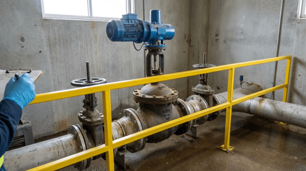
1. Introduction
In the hydraulic architecture of municipal and industrial water systems, automatic valves function as the primary logic gates for hydraulic control. Unlike isolation valves (gate, butterfly, ball) which are static in their operation (either open or closed), automatic valves are dynamic, modulating devices designed to regulate pressure, flow, level, or surge conditions autonomously. These devices are critical for Non-Revenue Water (NRW) reduction, asset protection against water hammer, and maintaining consistent service levels in potable water distribution and wastewater force mains.
The term “automatic valve” in this context broadly encompasses hydraulic pilot-operated control valves—often diaphragm or piston actuated—as well as specialized passive automatic devices such as check valves and pinch valves used for process control. These valves operate on the differential pressure of the line fluid itself, requiring no external power source for basic function, though many modern iterations integrate solenoids for SCADA interface.
From a regulatory and design standpoint, the selection of the Original Equipment Manufacturer (OEM) for these components is not merely a procurement detail; it is a fundamental engineering decision that dictates the system’s long-term hydraulic stability. The Safe Drinking Water Act (SDWA) and various state-level environmental mandates place a premium on system integrity. An automatic valve that fails to regulate pressure can lead to pipe bursts and contaminant intrusion. Conversely, a valve that hunts or chatters due to poor pilot design or sizing can induce fatigue failure in downstream infrastructure.
For consulting engineers and utility operators, the challenge lies in distinguishing between manufacturers based on engineering merit—casting quality, pilot precision, material compatibility, and support for complex hydraulic modeling—rather than brand familiarity. This article provides a technical, specification-focused analysis of the leading OEMs in the automatic valve sector, evaluating their suitability for rigorous municipal and industrial service. It sits within the broader subject of automatic valve automation and actuation options, which covers the full range of ways a valve can be commanded — hydraulic pilot, solenoid, pneumatic, and electric motor operator. Because the actuation method frequently determines which manufacturers are even eligible for a given specification, a later section extends this analysis to the electric actuator OEMs that supply the motorized side of the same distribution system.
2. How to Select This Valve Type
Selecting an automatic valve requires a granular analysis of system hydraulics. Unlike on/off valves, control valves interact dynamically with the fluid column. Improper selection often results in cavitation, noise, vibration, and premature failure. Engineers must move beyond nominal pipe size (NPS) and specify based on flow coefficients ($C_v$), rangeability, and material science.
Valve Function and Hydraulic Duty Cycle
The first step in specification is defining the control variable. Is the valve intended for Pressure Reducing (PRV), Pressure Sustaining/Relief (PSV), Flow Control, Level Control (Altitude), or Surge Anticipation?
Once the function is defined, the duty cycle must be analyzed. A PRV in a main distribution line sees continuous modulation, whereas a deluge valve or surge relief valve may sit static for months before requiring millisecond-response actuation.
Rangeability: A critical engineering metric is the ratio of maximum to minimum controllable flow. Municipal systems often experience high demand during the day and near-zero demand at night. If a valve is sized solely for fire flow (peak), it may operate in a “cracked open” position during low flow, leading to wire-drawing (seat erosion) and instability. Engineers should look for OEMs offering rolling diaphragm technology or dual-chamber designs that maintain stability at low flow rates.
Pressure Conditions and Cavitation
The differential pressure ($Delta P$) across the valve determines the potential for cavitation. As fluid accelerates through the valve restriction, pressure drops. If it drops below the vapor pressure of the liquid, bubbles form. As pressure recovers downstream, these bubbles collapse with significant energy, causing pitting and noise.
Engineers must calculate the Sigma ($sigma$) cavitation index for the application. If the application falls into a cavitation zone, the specification must mandate anti-cavitation trim. This usually involves slotted cages or stacked plates that stage the pressure drop, keeping local pressures above vapor pressure.
Materials of Construction
Body Materials: Ductile iron (ASTM A536) is the standard for municipal water, typically coated with fusion-bonded epoxy (FBE) to AWWA C550 standards. For aggressive industrial wastewater or seawater applications, specifications should upgrade to Nickel-Aluminum-Bronze or Duplex Stainless Steel.
Elastomers: The diaphragm and seals are the primary wear parts. EPDM is standard for potable water (chloramine resistance), while Buna-N (Nitrile) is preferred for wastewater containing hydrocarbons or oils.
Pilot System: The pilotry is the “brain” of the valve. In corrosive environments or vaults prone to flooding, specifying 316 Stainless Steel tubing and fittings rather than copper or brass is essential to prevent external corrosion and pilot failure.
Sealing Mechanisms and Actuation
Globe vs. Angle Body: While globe bodies are standard for inline piping, angle bodies offer lower head loss and can replace an elbow in the piping isometric, saving space in pump stations.
Diaphragm vs. Piston:
- Diaphragm Actuators: Preferred for water service due to lower friction, zero leakage, and simpler maintenance. They are less sensitive to particulates than pistons.
- Piston Actuators: Often used in high-pressure applications or where very linear control characteristics are required, but they are more susceptible to seizing if particulates get between the piston and liner.
Single vs. Double Chamber: A single-chamber valve uses line pressure on top of the diaphragm to close against upstream pressure. A double-chamber valve allows pressure to be applied to both sides of the diaphragm, providing positive control for both opening and closing. Double-chamber designs operate more smoothly at lower differential pressures and eliminate the need for a check feature in some applications.
Maintenance and Serviceability
Operational Expenditure (OPEX) is driven by ease of service. Engineers should evaluate:
- Top Entry Design: Can the cover be removed and the diaphragm/trim replaced without removing the valve body from the line?
- Pilot Strainers: Pilot lines are susceptible to clogging. High-quality specifications require large-surface-area strainers (often “Y” strainers) on the pilot supply line, ideally with a blow-off valve for easy cleaning.
- Jack-Screw Holes: On large valves, cover plates are heavy and under spring tension. Jack-screw holes are a safety feature for maintenance personnel.
3. Comparison Table
The following table provides a technical comparison of the leading OEMs for automatic valves. This data is intended to assist engineers in matching specific hydraulic challenges with the manufacturer’s core competencies. This is not a ranking of quality, as all listed manufacturers produce specification-grade equipment. Instead, it highlights the engineering focus and best-fit applications for each OEM.
| OEM | Core Valve Technology | Primary Applications | Key Engineering Strengths | Maintenance Considerations |
|---|---|---|---|---|
| Cla-Val | Hydraulic Pilot-Operated (Diaphragm) | Municipal Distribution, Aviation Fueling, Marine, Fire Protection | Extremely wide range of pilot functions; Anti-cavitation trim options; ubiquitous parts availability in North America; Link2Valves asset tracking. | Standard diaphragm maintenance; pilot tubing complexity can be high on multi-function valves; requires clean pilot supply. |
| Bermad | Double-Chamber Hydraulic Control | Irrigation, Municipal Water, Wastewater, Mining | Double-chamber technology allows low-pressure operation and positive opening; composite material options; high hydraulic efficiency (low head loss). | Unitized actuator assembly allows for quick change-outs; distinct design differs from traditional globe valves. |
| Singer Valve | Rolling Diaphragm Control | Pressure Management, NRW Reduction, Surge Control | Rolling diaphragm technology provides superior stability at low flows; Anti-Cavitation (AC) cages; MetroTrak electronic interface. | Single rolling diaphragm reduces hunting; simplified pilot systems; easy access to internal cage for inspection. |
| Red Valve / Tideflex | Passive Check & Pinch Valves | Wastewater, Stormwater, Outfalls, Slurries | Full-port passage (no obstruction); no mechanical parts to corrode; distinct “Duckbill” check valve technology; reliable in heavy solids. | Minimal maintenance (no pilots/seals); elastomer sleeve is the only wear part; sleeve replacement requires line depressurization. |
| Flomatic Corporation | Valve Bodies & Cycle Gard | Well Water, Pump Stations, Municipal Boosters | Cycle Gard constant pressure valves; high-quality stainless steel internals; vertical integration of casting; strong focus on check valves. | Simple, robust designs; unleaded bronze and stainless steel options standard; cartridge-style pilots for easy swap. |
4. Top OEM Manufacturers
The following section details the specific engineering characteristics of the five validated OEMs for automatic valves.
Cla-Val
Overview: Cla-Val is widely considered the benchmark for automatic control valves in the North American municipal water market. Their designs are based on the Hytrol (100-01) main valve, a hydraulically operated, diaphragm-actuated globe or angle pattern valve.
Engineering Focus: Cla-Val excels in versatility. By altering the pilot sub-assembly, the same main valve body can function as a pressure reducer, pressure retainer, surge anticipator, or level controller. A significant engineering advantage is their casting quality and the availability of diverse materials, including Monel and Titanium for extreme environments.
Technical Highlights:
- Anti-Cavitation (KO) Trim: This radial slotted cage design directs impinging flow toward the center of the recovery chamber, mitigating damage to the valve body during high pressure drops.
- Electronic Control: Their 340-series pilots and VC-22D controllers allow for seamless SCADA integration, enabling remote setpoint changes and flow modulation based on time or demand (critical for advanced pressure management).
- Fueling & Fire: Beyond water, Cla-Val holds a dominant position in aviation fueling and deluge fire systems, indicating a high reliability standard.
Bermad
Overview: Bermad brings a distinct design philosophy centered on double-chamber hydraulic actuation. While they offer single-chamber valves, their expertise lies in the “active” control provided by the double-chamber architecture.
Engineering Focus: The double-chamber design separates the control chamber from the line pressure. This allows the valve to be powered open or closed by an external source or the line pressure itself, providing immediate response without the “lag” sometimes associated with spring-return single-chamber valves. This is particularly advantageous in pump control applications where rapid opening/closing sequences are required to prevent surges.
Technical Highlights:
- 700 Series: Their flagship municipal valve featuring a “Y” pattern body, which offers a hydrodynamic flow path with high flow capacity and low head loss compared to standard globe valves.
- Composite Valves: Bermad is a leader in using engineered plastics for control valves in corrosive environments or smaller utility applications, offering chemical resistance that metal valves cannot match.
- Wastewater Capability: They offer specialized control valves designed to handle solids and wastewater, utilizing remote hydraulic commands to keep electronics out of the vault.
Singer Valve (Mueller)
Overview: Now a brand under Mueller Water Products, Singer Valve has historically distinguished itself through innovation in low-flow stability and cavitation management. Their engineering philosophy focuses heavily on solving the “hunting” issues prevalent in distribution networks.
Engineering Focus: Singer is renowned for the Rolling Diaphragm. Unlike a standard flat diaphragm which can warp or distort at low valve openings, the rolling diaphragm maintains a constant effective area throughout the stroke. This results in incredibly stable modulation down to near-zero flow, eliminating the need for a secondary low-flow bypass valve in many PRV stations.
Technical Highlights:
- Anti-Cavitation Cages: Singer’s dual-cage technology fights cavitation by breaking the pressure drop into two stages. The cages are designed to contain the vapor collapse within the cage center, away from metal surfaces.
- Single Rolling Diaphragm (SRD): This technology provides linear control and reduces hysteresis, making the valve highly responsive to small pressure fluctuations.
- Pilot System: Singer pilots are often praised for their robust construction and ease of setting. Their 106-PG main valve is the platform for almost all their control configurations.
Red Valve / Tideflex
Overview: Red Valve and its Tideflex division occupy a unique niche. They do not manufacture the complex pilot-operated globe valves typical of the other OEMs listed here. Instead, they specialize in pinch valves and passive check valves.
Engineering Focus: The core technology is elastomer engineering. Their valves are designed for fluids that destroy standard control valves: raw sewage, sludge, mine tailings, and stormwater.
Tideflex Check Valves: These are “duckbill” valves made entirely of fabric-reinforced elastomer. They require no external power, have no mechanical hinges or flappers to rust or seize, and are self-draining.
Control Pinch Valves: For throttling abrasive slurries or wastewater, Red Valve uses pneumatic or hydraulic pressure to squeeze a rubber sleeve. This provides linear flow control with zero dead volume and no obstruction to flow when open.
Technical Highlights:
- Solids Handling: The ability to close drop-tight around entrapped solids (rags, debris) makes them superior for wastewater pump stations.
- Hydraulic Characteristics: While they have different head loss curves than globe valves, the Tideflex design offers very low cracking pressure and prevents backflow in outfall lines without the risk of “sticking” open.
- Mixing Systems: Their TMS (Tideflex Mixing System) utilizes the valve nozzles to improve water quality in storage tanks.
Flomatic Corporation
Overview: Flomatic is a highly integrated manufacturer, notable for owning their own foundry operations, which allows for strict quality control over lead-free bronze and stainless steel castings. While famous for check valves, they are a major player in the automatic control valve space for pump and pressure applications.
Engineering Focus: Flomatic focuses on robustness and solving specific pump control problems. Their Cycle Gard series is a staple in the industry for constant pressure pump control, eliminating the effects of pump cycling and water hammer.
Technical Highlights:
- Cycle Gard (CIV): These valves maintain a constant downstream pressure regardless of pump flow, allowing a fixed-speed pump to operate like a variable speed system within certain hydraulic limits. They feature a unique stop that prevents the valve from closing completely, ensuring minimum cooling flow for the pump.
- Unleaded Bronze: Flomatic was an early pioneer in unleaded alloys for potable water compliance, ensuring all wetted parts meet strict NSF/ANSI 61 & 372 standards.
- Automatic Control Valves (C-Series): Their pilot-operated valves utilize a simplified design that is easy to service, often preferred in smaller municipal booster stations and rural water districts.
5. Application Fit Guidance
Successful engineering design relies on matching the specific strengths of an OEM to the application environment. Below are generalized “best-fit” scenarios based on field performance and design characteristics.
Municipal Water Distribution (Clean Water)
Primary Candidates: Cla-Val, Singer Valve, Bermad.
For standard Pressure Reducing Valves (PRV) stations, all three are excellent.
- Select Singer if the station handles extreme variations in flow (e.g., high fire flow + low night flow) to leverage the rolling diaphragm’s stability without a low-flow bypass.
- Select Cla-Val for large networks requiring uniformity of spare parts, advanced electronic metering integration, or extremely large valve sizes (up to 36″+).
Wastewater & Sludge Handling
Primary Candidates: Red Valve / Tideflex, Bermad.
Standard pilot-operated valves will clog instantly in raw sewage.
- Select Red Valve for check valve applications (pump discharge, outfall) and flow control of sludge where full-port passage is required to pass solids.
- Select Bermad (Wastewater Series) if precise hydraulic control (pressure reduction/relief) is required on a force main, as they offer specialized pilots and bodies designed to minimize clogging risks.
Pump Stations (Well & Booster)
Primary Candidates: Flomatic, Cla-Val.
- Select Flomatic for well pumps and booster stations requiring “Constant Pressure” control (Cycle Gard) or high-reliability foot valves and check valves.
- Select Cla-Val for complex Deep Well Pump Control valves that require solenoid interfacing to synchronize with motor starters (delay opening until pump creates pressure, close before pump stops).
High Pressure & Cavitation
Primary Candidates: Singer Valve, Cla-Val.
When $Delta P$ is high (e.g., dropping pressure from a high-elevation reservoir to a lower zone), standard bodies will fail.
- Select Singer for their dual-cage Anti-Cavitation technology, which is highly effective at containing cavitation damage.
- Select Cla-Val for their KO anti-cavitation trim, a proven solution in high-head applications.
6. Engineer & Operator Considerations
Installation Best Practices
Straight Pipe Runs: Turbulence is the enemy of stable control. A common specification mistake is placing an automatic valve immediately downstream of an elbow or isolation valve. Engineers should specify a straight pipe run of at least 5 pipe diameters upstream and 3 diameters downstream of the control valve. This ensures the velocity profile entering the valve is uniform, improving pilot accuracy.
Air Release: Air pockets trapped in the pilot system or the main valve cover can cause erratic operation and “spongy” control. Automatic air release valves should be installed at the high points of the piping immediately upstream of the control valve to prevent air binding.
Common Specification Mistakes
Oversizing: The most common error is sizing the control valve to match the line size. A 10-inch pipe does not automatically require a 10-inch PRV. If the valve operates consistently in the bottom 10-15% of its stroke, it will chatter and wear prematurely. Valves should be sized based on flow velocity and $C_v$ requirements, often resulting in a valve one or two sizes smaller than the main line (using reducers).
Ignoring Pilot Materials: In vault environments, condensation and groundwater are common. Specifying standard copper tubing for pilots can lead to external corrosion. For long-term reliability, specify 316 Stainless Steel tubing and fittings for all pilot assemblies.
Maintenance Access & Spare Parts
Isolation: Every automatic valve must be installed with isolation valves upstream and downstream to facilitate maintenance.
Spare Parts Strategy: Diaphragms and rubber seats have a shelf life and a service life. Operators should standardize on one or two OEMs within a distribution zone to minimize inventory. Mixing Cla-Val, Singer, and Bermad in the same pressure zone complicates the spare parts inventory and requires operators to learn multiple pilot adjustment procedures.
Operational Lessons: Water Quality
In systems with high mineral content or old unlined cast iron pipes, particulate matter can wreak havoc on pilots. While Y-strainers are standard, they require manual flushing. In areas with known debris issues, consider specifying “self-flushing” pilot filters or external commercial strainers upstream of the valve assembly.
7. Electric and Motorized Actuation OEM Landscape
The five OEMs profiled above build valves that derive their control energy from the line fluid itself. A parallel and equally important market supplies electric motor operators that drive isolation and modulating valves from an external power source under SCADA command. Where a hydraulic pilot-operated valve responds to a local pressure signal, an electrically actuated valve responds to a control system instruction, which makes it the appropriate choice when the required action depends on information the valve cannot sense at its own location — reservoir level several miles away, a treatment process state, or an operator command from a control room.
Electric Actuator OEMs for Municipal Service
Electric actuator selection is governed by a different parameter set than hydraulic control valve selection. The controlling factors are output torque with an adequate safety margin over the valve’s breakaway requirement, duty rating expressed as starts per hour and percentage on-time, enclosure rating for the installation environment, and the fieldbus or hardwired protocol required to integrate with the plant control system. The head-to-head evaluation of Rotork vs AUMA automatic valves equipment examines the two dominant manufacturers in this segment, covering their differing approaches to torque sensing, local control interface, and non-intrusive commissioning.
Several specification points deserve particular attention. Torque sizing should carry a margin above the valve manufacturer’s stated breakaway torque, not the running torque, because breakaway after a long dormant period is substantially higher than steady-state operation. Duty rating matters more than most specifications acknowledge: an actuator rated for isolation service will overheat if pressed into continuous modulating duty, and modulating-rated units carry a meaningful capital premium for exactly that reason. Enclosure rating should reflect the realistic worst case for the installation — a submersible rating is appropriate for any actuator in a vault that has ever flooded, regardless of what the design drawings assume about drainage.
Failure position is the decision most frequently deferred and most consequential in service. On loss of power or loss of signal, an actuator can be specified to fail in place, fail open, or fail closed, and each requires different hardware. Fail-in-place is the default for most electric actuators and is often acceptable, but it is a genuine engineering decision on any valve whose position matters during an outage — a reservoir inlet, a chlorine contact basin outlet, or a force main isolation point. Where a defined failure position is required, either a spring-return unit or a battery or capacitor backup module must be specified explicitly at procurement, because retrofitting one later usually means replacing the actuator.
8. Selection & Specification Framework
With both hydraulic and electric actuation options in view, the selection sequence below reflects how the decision normally resolves in practice.
Step 1: Determine Whether the Control Signal Is Local or Remote
This single question separates the two families of equipment. If the required action depends entirely on a condition the valve can sense at its own location — downstream pressure, upstream pressure, differential across itself — a hydraulic pilot-operated valve is normally simpler, cheaper, and more reliable, and it continues functioning through a power outage. If the required action depends on information originating elsewhere in the system, or on an operator decision, an electric actuator is the appropriate answer. Applications requiring both, such as a pressure reducing valve with remote setpoint adjustment, are served by a hydraulic main valve with solenoid-operated pilot control rather than by a fully motorized valve.
Step 2: Complete the Hydraulic Analysis Before Shortlisting Manufacturers
As established earlier in this article, flow coefficient requirements, rangeability across the full diurnal demand curve, and the cavitation index at the governing differential pressure determine the valve size and trim. These calculations are manufacturer-independent, and completing them first prevents the common error of selecting a brand and then sizing to that brand’s available options. Where the cavitation analysis indicates a problem, anti-cavitation trim becomes a mandatory line item rather than an upgrade to be value-engineered out during bidding.
Step 3: Weigh Standardization Against Best Technical Fit
The spare parts argument for standardizing on one or two OEMs within a pressure zone is real and is discussed in the operator considerations below. It should be weighed against the cost of forcing a manufacturer into an application outside its strengths — specifying a pilot-operated globe valve for raw sewage service to preserve inventory uniformity, for instance, will produce a valve that clogs regardless of how many spare diaphragms are on the shelf. The workable compromise is standardization by service category rather than across the entire system.
Step 4: Specify the Support Requirement Explicitly
Control valves and actuators both require setting, tuning, and periodic adjustment by someone who understands the pilot logic or the actuator configuration. Where utility staff do not have that capability in-house, factory startup support, operator training, and a defined service response time belong in the specification as deliverables with associated line items. Assuming this support will be available informally after commissioning is a common source of valves that end up locked in a fixed position because nobody remaining on staff knows how to adjust them.
9. Field Notes
Commissioning Considerations
Automatic control valves are commissioned against system behavior, not bench performance, and the plant must be able to generate the range of conditions the valve will actually see. Set pilots during a low-demand period and verify stability again at high demand, since a valve tuned only at one end of its range frequently hunts at the other. Flush pilot supply lines and clean strainers before final setting; construction debris in a pilot line will produce erratic behavior that is easily mistaken for a valve defect. For electric actuators, verify torque switch settings and limit switch positions with the valve under actual line pressure rather than dry, and record the final configuration somewhere other than the actuator itself.
Pro Tip
Photograph every pilot assembly at commissioning, with the tubing runs clearly visible, and store the images with the valve’s asset record. Multi-function pilot systems are effectively undocumented once the startup technician leaves, and a plant facing a rebuild five years later routinely has no reference for how the tubing was originally routed. The photographs cost nothing to take and repeatedly save a full day of trial-and-error reassembly, particularly on surge anticipator and pump control valves where the pilot logic is not obvious from inspection.
Additional Specification Pitfalls
Beyond oversizing and pilot material selection covered in the operator considerations, several errors recur. Omitting a pressure gauge upstream and downstream of every control valve leaves operators with no way to confirm the valve is doing what it was set to do. Specifying a valve without a bypass on a single-feed pressure zone means the zone must be taken out of service for any valve maintenance. Failing to state the required failure position for electric actuators leaves it to the supplier’s default. And specifying valve position feedback to SCADA without specifying the signal type and range produces integration work that surfaces during commissioning rather than during design.
Common Mistake
Treating the valve vault as an afterthought. Control valves fail far more often from vault conditions than from valve defects: standing water corrodes pilot tubing and destroys electric actuators, inadequate access prevents the cover removal that top-entry service depends on, and insufficient clearance around the valve makes routine diaphragm replacement a confined-space ordeal. Specify vault drainage that actually functions, hatch openings sized for the largest component that must be removed, and clearance dimensions verified against the manufacturer’s service requirements rather than assumed.
Operations and Maintenance Comparison
Maintenance burden differs by valve family. Hydraulic pilot-operated valves concentrate effort in diaphragm and seat replacement on a multi-year interval, plus routine pilot strainer cleaning that is easy to defer and produces gradual control degradation when deferred. Passive elastomer check valves require almost no attention until sleeve replacement, which then demands line depressurization and a planned outage. Electric actuators need periodic lubrication, seal inspection, and verification that heaters are functioning in humid enclosures — low-effort work whose omission causes the moisture ingress that is the leading cause of actuator failure.
10. Design Details & Standards
Applicable Standards
Automatic valve specifications should reference recognized standards rather than manufacturer literature. Control valve bodies in municipal water service are commonly specified to AWWA C530 for pilot-operated control valves, with ductile iron castings to ASTM A536 and fusion-bonded epoxy coating to AWWA C550. Wetted materials in potable service must meet NSF/ANSI 61 for drinking water system components and NSF/ANSI 372 for lead content. Flange dimensions follow ASME B16.1 or B16.42 depending on material and class. Electric valve actuators are commonly specified to AWWA C542, with enclosure ratings per NEMA 250 or IEC 60529, and control valve sizing and cavitation evaluation per ISA-75.01 and the associated ISA recommended practices.
Key Parameters That Differ by Valve Family
Flow coefficient and rangeability govern hydraulic control valve selection and determine whether the valve will modulate stably across the actual demand curve. The cavitation index at the governing differential pressure determines whether standard or anti-cavitation trim is required, and it must be evaluated at the worst-case combination of high upstream pressure and low downstream demand rather than at the nominal design point. For electric actuators, output torque relative to valve breakaway torque, duty cycle rating, and stroke time govern the selection, with stroke time frequently constrained by surge considerations rather than by operational preference — closing too quickly on a long force main can generate a pressure transient more damaging than the condition the valve was installed to address.
Specification Checklist
- Control function defined explicitly: pressure reducing, sustaining, flow, level, or surge anticipation
- Full demand range documented, including minimum night flow and maximum fire flow
- Valve sized on flow coefficient and velocity, not matched to line size by default
- Cavitation index evaluated at worst-case differential; anti-cavitation trim specified where indicated
- Body, trim, and elastomer materials selected against actual fluid and coating standards stated
- 316 stainless steel pilot tubing and fittings specified for all vault installations
- Pilot strainer type, mesh, and blow-off provision specified
- Straight pipe run requirements stated: minimum five diameters upstream, three downstream
- Isolation valves upstream and downstream, plus bypass where the zone has a single feed
- Pressure gauges specified upstream and downstream of each control valve
- For electric actuators: torque margin over breakaway, duty rating, enclosure rating, and stroke time
- Failure position on loss of power or signal stated explicitly, with the hardware required to achieve it
- SCADA signal type, range, and position feedback requirements defined during design
- Vault drainage, hatch opening, and service clearance verified against manufacturer requirements
- Factory startup, operator training, and service response time included as specification deliverables
11. Frequently Asked Questions
When should a hydraulic control valve be chosen over an electrically actuated one?
Choose hydraulic when the control action depends only on conditions the valve can sense locally, when the installation has no reliable power, or when continued function through an outage matters. Pilot-operated valves draw their operating energy from the line, so they keep regulating during a power failure — a significant advantage in distribution vaults. Choose electric actuation when the required action depends on remote information or operator command, or when the valve must be positioned to an arbitrary setpoint under control system supervision.
Why does an oversized control valve fail prematurely?
A valve sized to the pipe rather than to the flow spends most of its life near the closed end of its stroke, where a small position change produces a large flow change. The result is instability, seat erosion from high-velocity flow through a narrow opening, and mechanical wear from continuous hunting. Sizing on the required flow coefficient frequently yields a valve one or two sizes below the line, installed with reducers — a configuration that looks wrong on a drawing and performs substantially better in service.
How many OEMs should a utility standardize on?
One or two per service category is the practical target. Standardizing reduces spare diaphragm and seat inventory and, more importantly, reduces the number of distinct pilot adjustment procedures operators must know. The limit is application fit: forcing a single manufacturer across clean water, wastewater, and pump control duties will produce at least one poor match. Standardize within a category and accept a different supplier where the service demands it.
What causes control valve hunting, and how is it diagnosed?
Hunting is most commonly caused by oversizing, by turbulent inlet flow from insufficient straight pipe upstream, by air trapped in the pilot system or valve cover, or by a partially clogged pilot strainer. Diagnosis proceeds in that order because the fixes get progressively cheaper: confirm the valve is not operating at the bottom of its stroke, verify the upstream piping configuration, bleed air from the cover and pilot lines, then clean the strainer. Only after those are eliminated is pilot replacement or retuning warranted.
What is the most common cause of premature failure in valve vaults?
Water. Standing water in a vault corrodes copper or brass pilot tubing from the outside, floods electric actuator enclosures that were specified to a weatherproof rather than submersible rating, and makes routine maintenance unpleasant enough that it gets deferred. Specifying stainless pilot tubing, submersible-rated actuator enclosures for any vault with flooding history, and drainage that has been verified rather than assumed addresses the majority of premature failures in this equipment class.
Key Takeaways
- Local signal means hydraulic; remote signal means electric — this single question resolves most of the actuation decision before any manufacturer is considered.
- Size on flow coefficient, never on line size — oversizing is the most common specification error and the leading cause of hunting, seat erosion, and premature wear.
- Evaluate cavitation at the worst case, not the design point — high upstream pressure combined with low night demand governs, and anti-cavitation trim is a requirement rather than an upgrade when the index indicates it.
- Specify the failure position explicitly for electric actuators — fail-in-place is the default and is often wrong, and correcting it later usually means replacing the unit.
- The vault kills more valves than the valve does — drainage, access, clearance, and stainless pilot tubing prevent the majority of premature failures.
- Standardize by service category, not across the system — inventory uniformity is valuable but not worth forcing a manufacturer into an application outside its strengths.
- Document the pilot configuration at commissioning — multi-function pilot logic is effectively undocumented once the startup technician leaves the site.
12. Conclusion
The selection of an automatic valve OEM is a balance between hydraulic performance requirements and operational practicality. There is no single “best” manufacturer; rather, there is a best fit for a given set of hydraulic parameters.
Cla-Val offers the safety of ubiquity and a massive range of pilot options, making them the default for general municipal distribution. Singer Valve provides technically superior solutions for low-flow modulation and high-cavitation environments through their rolling diaphragm and cage designs. Bermad offers high-efficiency double-chamber designs and composite material options. Red Valve is the undisputed choice for handling solids and wastewater where mechanical mechanisms would fail. Flomatic delivers robust, high-quality solutions for pump control and well applications.
For the consulting engineer, the goal is to write a specification that is performance-based. By focusing on low-flow stability, cavitation indices, and material longevity, and by rigorously evaluating these five proven OEMs against those criteria, utilities can ensure resilient and reliable system operation for decades.