
Automatic Valves Automation: Actuation Options
INTRODUCTION
In municipal water distribution and industrial wastewater treatment, process engineers frequently agonize over pump selection, pipe routing, and advanced biological treatment modeling. Yet, one of the most common causes of process failure, water hammer, and localized flooding stems from a fundamentally overlooked element: the interface between the control system and the physical flow. This is where Automatic Valves Automation: Actuation Options come into play.
A surprising and costly reality in plant operations is that a perfectly specified $30,000 control valve will fail to perform its duty if paired with a misapplied actuator. Engineers often treat actuators as an afterthought or a “packager’s problem,” relying on basic catalog defaults rather than rigorous operating envelope analysis. This leads to undersized motors burning out on modulating duty, pneumatic systems failing due to wet instrument air, or critical isolation valves failing to close during a power outage.
Automatic valve actuation is deployed across nearly every facet of fluid handling: pump discharge control, filter gallery sequencing, sludge wasting, chemical dosing, and emergency isolation. These operating environments range from climate-controlled MCC rooms to submerged underground vaults and highly corrosive hydrogen sulfide (H2S) environments in wastewater headworks.
Properly specifying the actuation technology—whether electric, pneumatic, hydraulic, or electro-hydraulic—is a critical decision point. A poor choice directly impacts facility reliability, increases operations and maintenance (O&M) burdens, and severely limits the efficacy of a plant’s SCADA system. This comprehensive guide will help consulting engineers, utility decision-makers, and plant operators navigate the complexities of Automatic Valves Automation: Actuation Options, providing unbiased, specification-safe criteria for real-world applications.
This guide also serves as the entry point for the automatic valve material on this site, covering the equipment category as a whole before going deep on actuation technology. Automatic valves sit within the broader family of valves used in water treatment, and the distinction that defines the category is not the valve body at all but what drives it: an automatic valve is a conventional valve body paired with a powered actuator and a control interface. Nearly every specification failure in this equipment class traces to treating those three elements as separate purchases rather than as one engineered assembly.
AUTOMATIC VALVES: TYPES AND SUBTOPIC OVERVIEW
Before working through actuation selection, it is worth establishing what the category actually contains and where its boundaries sit against adjacent equipment. The subsections below cover the defining elements, the valve bodies that are commonly automated, and the manufacturer landscape.
What Makes a Valve “Automatic”
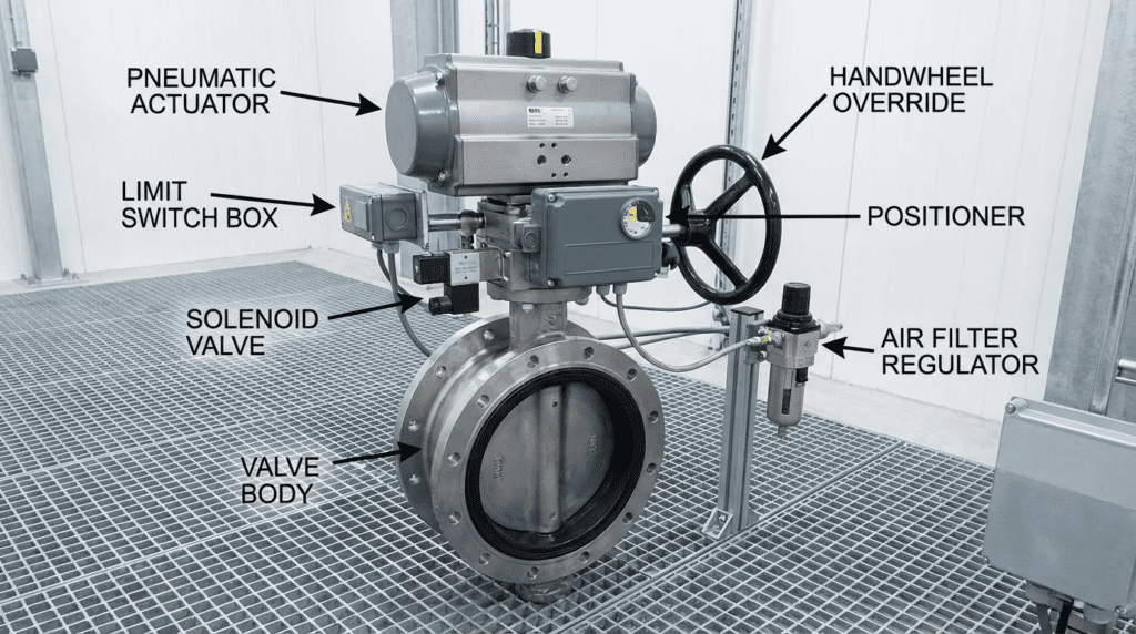
An automatic valve is an assembly of three components: a valve body that controls flow, an actuator that supplies the motive force, and a control interface that tells the actuator what to do. The valve body determines the torque profile and the flow characteristic; the actuator determines whether that torque can actually be delivered across the full stroke under maximum differential pressure; and the control interface determines whether the assembly can be trusted to do the right thing when the signal or the power disappears. The bulk of this guide addresses the second and third elements, because the first is usually selected on process grounds before automation is even considered.
A useful boundary to draw is between self-actuated and powered valves. Pressure-reducing valves, altitude valves, and conventional check valves operate automatically in the sense that they respond to process conditions without an external signal, but they are not automatic valves in the sense used here — they carry no actuator and no control interface, and they cannot be commanded from a SCADA screen. The smallest genuinely automatic valves are typically solenoid valves, where the actuator is an electromagnetic coil acting directly on the plug or on a pilot port. Solenoids handle small-bore on/off duty efficiently and are also the pilot devices that route air to pneumatic actuators on larger valves, which is why a solenoid failure so often presents as a large valve refusing to move.
Valve Bodies Commonly Automated
Four body styles account for most automated installations in water and wastewater, and each brings a different torque profile that the actuator must accommodate. Butterfly valves are the most frequently automated in large-diameter service, and they carry the most demanding torque curve because hydrodynamic torque peaks mid-stroke rather than at the seat. Eccentric plug valves dominate wastewater and sludge service, where the controlling requirement is unseating torque after the valve has sat closed in solids. Gate and knife gate valves present a multi-turn rising or non-rising stem problem rather than a quarter-turn one, changing the actuator type entirely. Ball valves sit at the simpler end, with a predictable quarter-turn profile and comparatively modest dynamic torque.
Which of these is appropriate for a given service is a body-selection question covered in the site’s broader guidance on wastewater treatment valves. The point for automation purposes is that the body is chosen first and then imposes its torque profile on the actuator decision — never the reverse. Engineers who select an actuator platform for standardization reasons and then fit valve bodies to it routinely end up with units that are adequate at the seat and marginal at 70 degrees open.
Manufacturer Selection
The actuator market is more concentrated than the valve market, with a handful of suppliers accounting for most municipal specifications and meaningful differences between them in diagnostics, network support, enclosure construction, and service availability. A review of the top OEMs for automatic valves covers the principal suppliers and how their product lines differ, along with head-to-head comparisons of the major actuator manufacturers. Supplier choice deserves more weight here than in most equipment categories for two reasons: firmware and diagnostic capability vary substantially and are difficult to change after installation, and regional service coverage determines how long a failed actuator keeps a valve in manual operation. Utilities standardizing a plant or a distribution system on one actuator platform gain real advantages in spare parts, technician familiarity, and SCADA integration effort, provided the platform genuinely covers the torque range the site requires.
HOW TO SELECT / SPECIFY
Selecting the optimal actuation technology requires evaluating the intersection of mechanical torque requirements, process control needs, environmental constraints, and lifecycle costs. The following criteria represent the engineer-level considerations necessary for robust specification.
Duty Conditions & Operating Envelope
The foremost consideration when navigating Automatic Valves Automation: Actuation Options is the duty cycle. Actuators are generally classified by their operational mode:
- Isolating (On/Off) Duty: Typically classified as AWWA Class A or B, these valves operate infrequently (e.g., a few times a day). The actuator must provide high breakaway torque but does not require continuous heat dissipation.
- Inching/Positioning Duty: Class C duty involves occasional positioning, requiring the actuator to start and stop frequently without overheating.
- Continuous Modulating Duty: Class D duty is for closed-loop control (e.g., maintaining a setpoint pressure or flow rate). Modulating actuators must handle continuous starts/stops (often up to 1,200 starts per hour for electric units) with zero deadband and highly robust gearing to prevent premature wear.
Furthermore, the operating envelope must consider flow rates, differential pressures, and the valve’s specific hydrodynamic torque curve. For example, a high-performance butterfly valve exhibits varying torque requirements depending on the disc angle and fluid velocity, requiring an actuator that matches or exceeds this profile at every degree of travel.
Materials & Compatibility
Water and wastewater environments are notoriously harsh. Material selection for actuators is just as vital as it is for the wetted components of the valve.
- Corrosion Resistance: In municipal wastewater, H2S gas rapidly attacks copper and silver components. Actuator enclosures must feature robust coatings (e.g., two-part epoxy or polyurethane) and utilize conformal-coated circuit boards.
- Enclosure Ratings: For indoor/outdoor installations, NEMA 4X (IP66/IP67) is typical. For vaults subject to flooding, NEMA 6P (IP68) is required, necessitating double-sealed terminal compartments to protect internal electronics even if the field wiring cover is removed.
- Internal Mechanisms: Pneumatic cylinders should utilize hard-anodized aluminum or stainless steel, coupled with self-lubricating seals to withstand dirty environments and prevent internal scoring.
Hydraulics & Process Performance
The speed of actuation directly impacts system hydraulics. Rapid valve closure can induce transient pressure spikes (water hammer) that exceed pipe pressure ratings, leading to catastrophic failure. Actuator selection must account for:
- Adjustable Operating Speeds: The ability to tune open/close times independently. Hydraulic and pneumatic actuators achieve this via flow control valves, while smart electric actuators use variable frequency drives (VFDs) or pulsed operation to manipulate speed profiles.
- Resolution and Deadband: For modulating control, the actuator must respond to minute changes in the control signal (typically <0.1% resolution) without hunting or overshooting, which can destabilize the process loop.
Installation Environment & Constructability
Physical constraints heavily influence the choice of actuator technology. Pneumatic actuators are typically more compact and lighter than their electric counterparts, making them advantageous for tight pipe galleries or elevated chemical piping where structural supports are limited.
However, pneumatics require an instrument air infrastructure (compressors, dryers, regulators, and tubing). If a remote reservoir site lacks compressed air, pulling electrical power for an electric actuator is usually more feasible and cost-effective than installing a dedicated compressor station.
Reliability, Redundancy & Failure Modes
A critical analysis of failure modes dictates the necessity for fail-safe configurations. In the event of a power loss or control signal failure (LOS), what must the valve do?
- Fail-Closed / Fail-Open: Essential for chemical dosing or pump discharge to prevent uncontrolled release or backflow.
- Fail-Last Position: Common for filter effluent valves where maintaining the current state is preferred over a sudden shutdown.
Pneumatic and electro-hydraulic actuators naturally excel at fail-safe operations via mechanical spring-return mechanisms or pressurized accumulators. Electric actuators traditionally struggle with true mechanical fail-safe capabilities, often relying on internal battery backups or supercapacitors, which introduce a maintenance burden and a finite lifespan.
Controls & Automation Interfaces
Modern plants rely heavily on integrated SCADA systems. When evaluating Automatic Valves Automation: Actuation Options, the control interface is paramount:
- Analog/Hardwired: Traditional 4-20mA signals for control and feedback, coupled with discrete 24VDC/120VAC signals for open/close commands and fault alarms.
- Digital Networks: Fieldbus protocols (Modbus RTU, Profibus DP) and Industrial Ethernet (EtherNet/IP, PROFINET) allow for deep diagnostic data retrieval, including torque profiling, cycle counts, and predictive maintenance alerts over a single network cable.
Maintainability, Safety & Access
Actuators must be safely accessible for maintenance. OSHA requirements and basic ergonomics dictate that handwheels for manual override should not require operators to build scaffolding for routine access. Extension stems, chain wheels, or remote-mounted controls are required for elevated valves.
Safety features must include independent lockout/tagout (LOTO) points for both the power supply and the mechanical declutch mechanism. Pneumatic systems must include bleed valves to safely vent stored energy before maintenance.
Lifecycle Cost Drivers
Engineers must balance Capital Expenditure (CAPEX) against Operational Expenditure (OPEX). A Total Cost of Ownership (TCO) analysis over a 20-year horizon reveals stark differences:
- Electric Actuators: Higher initial CAPEX, complex electronics to maintain, but very high energy efficiency and low physical maintenance overhead.
- Pneumatic Actuators: Lower initial CAPEX and simple to repair, but highly inefficient from an energy standpoint due to the continuous running of instrument air compressors and the inevitable air leaks across the plant network.
COMPARISON TABLES
The following tables provide a high-level engineering comparison of the primary Automatic Valves Automation: Actuation Options. Table 1 outlines the core technologies, evaluating their technical features and inherent limitations. Table 2 provides a practical application matrix to help engineers align technologies with specific water/wastewater scenarios.
Table 1: Actuation Technologies Comparison
| Technology Type | Primary Features & Strengths | Best-Fit Applications | Limitations & Considerations | Typical Maintenance |
|---|---|---|---|---|
| Electric (Multi-Turn / Quarter-Turn) | High accuracy, programmable speed/torque, deep SCADA diagnostics via network protocols, clean installation (no fluid/air lines). | Pump stations, filter galleries, remote reservoirs, continuous modulating control (VFD models). | Heavy, bulky, challenging to achieve true mechanical fail-safe (requires batteries/capacitors). High initial CapEx. | Battery replacement (if fail-safe), oil bath/grease inspection, firmware updates, visual inspection of seals. |
| Pneumatic (Rack & Pinion / Scotch Yoke) | Extremely fast operation, highly reliable mechanical spring-return (fail-safe), compact footprint, low initial cost per unit. | Rapid isolation, chemical dosing lines, hazardous/explosive environments (Class I Div 1). | Requires clean, dry instrument air infrastructure. Susceptible to freezing if air isn’t perfectly dry. Poor for precise modulation without complex positioners. | O-ring/seal replacement, lubrication of cylinder, maintenance of air compressors/dryers, positioner calibration. |
| Hydraulic | Unmatched power density, extremely high torque in a compact size, highly robust against shock loads and continuous duty. | Large diameter transmission mains, high-pressure pump discharge, massive sluice gates. | Requires central Hydraulic Power Unit (HPU). Risk of environmental contamination (oil leaks). High CapEx and complex installation. | Hydraulic fluid analysis, filter replacements, high-pressure hose inspections, accumulator pre-charge checks. |
| Electro-Hydraulic | Combines electric control with hydraulic power. Self-contained (no external lines). Excellent mechanical fail-safe via springs/accumulators. | Critical pump discharge valves, high-torque modulating valves, remote locations requiring true fail-safe without air. | Very high CapEx. Complex internal machinery. Heavier than standard electric actuators. | Self-contained system requires less routine maintenance than central hydraulics, but repairs require specialized factory service. |
Table 2: Application Fit Matrix
| Application Scenario | Key Constraints | Recommended Technology | Relative Cost Impact | Operator / Maintenance Impact |
|---|---|---|---|---|
| Remote Water Tank Vault (Altitude Valve) | No instrument air, frequent power bumps, requires fail-closed operation, submerged vault (IP68). | Electric (Battery backup, NEMA 6P) or Electro-Hydraulic. | Moderate to High | Requires battery monitoring and regular desiccant replacement in the vault. |
| Wastewater Plant Filter Gallery (20+ Valves) | High density of valves, rapid sequencing required, space-constrained pipe gallery. | Pneumatic (Double-acting or spring-return with smart positioners). | Low (per valve), but requires central air system. | Low unit maintenance, but requires vigilant air system O&M to prevent moisture damage. |
| Large Pump Station Discharge (48″ Butterfly) | Massive unseating torque, requires highly controlled speed to prevent water hammer, requires emergency closure on pump trip. | Electro-Hydraulic or Hydraulic with accumulators. | High | Requires specialized training for hydraulic systems and high-pressure safety procedures. |
| Chemical Dosing Room (Sodium Hypochlorite) | Highly corrosive atmosphere, small valve sizes, critical fail-closed requirement. | Pneumatic (Spring-return with fiberglass/composite enclosure). | Low | Simple swap-out maintenance. Operator must ensure positioner is chemically resistant. |
ENGINEER & OPERATOR FIELD NOTES
Theoretical sizing is only the first step. The true test of any specification lies in its execution in the field. Below are critical field notes gathered from commissioning engineers and plant superintendents regarding Automatic Valves Automation: Actuation Options.
Commissioning & Acceptance Testing
Never bypass rigorous testing. The Factory Acceptance Test (FAT) should verify that the actuator and valve are tested as an assembled unit. Testing an actuator on a bench does not account for the valve stem tolerances or mounting bracket deflection.
- FAT Checkpoints: Verify breakaway torque limits, confirm the fail-safe action timing (e.g., “valve must close within 60 seconds on power loss”), and validate network communication mapping.
- Site Acceptance Test (SAT): The SAT must include testing under actual hydrodynamic conditions. A common punch-list item is verifying that the actuator’s speed control does not induce transient pressures during the final 10% of closure (where the flow velocity spikes).
- Network Comms: For smart electric actuators, force a “loss of signal” (LOS) state from the PLC to ensure the actuator responds according to the specified fail-safe parameter.
Common Specification Mistakes
Engineers frequently specify actuator torque based purely on the valve manufacturer’s clean-water torque curves. In primary sludge or anaerobic digester applications, grease and grit cause valves to become “sticky.” If an actuator is sized with a standard 1.25 safety factor, it will likely fail to unseat a plug valve that has been sitting closed in thick sludge for three months. For heavy wastewater applications, a safety factor of 1.5 to 2.0 on unseating torque is highly recommended.
Other typical specification errors include:
- Ambiguous Duty Cycles: Specifying “modulating” without defining the required starts-per-hour. A standard actuator might handle 60 starts/hour, whereas true continuous modulation requires an actuator rated for 1,200+ starts/hour.
- Over-Specification: Demanding NEMA 6P (submersible) enclosures for indoor, climate-controlled pump rooms drives up CAPEX unnecessarily and complicates maintenance access.
- Mismatched Stems: Failing to specify whether the valve stem has a rising or non-rising configuration, leading to actuators being delivered without the necessary hollow stem tubes.
O&M Burden & Strategy
Maintenance strategies shift drastically depending on the chosen actuation technology. A robust O&M strategy should include:
- Electric Actuators: Predictive maintenance is key. Utilize SCADA to monitor torque profiles over time. If the running torque steadily increases month-over-month, the valve bearings are likely failing or scale is building up. PM includes replacing internal desiccant packs every 1-2 years and checking oil/grease levels every 5 years.
- Pneumatic Actuators: The actuator itself is virtually maintenance-free, but the air quality requires daily vigilance. Install auto-drains on compressor receivers and check the dew point. A single failure of an air dryer can push moisture into dozens of actuators, causing internal rusting and total system failure.
Troubleshooting Guide
When an automated valve fails to operate, follow this diagnostic hierarchy:
- Isolate the Problem (Mechanical vs. Control): Put the actuator in “Local/Manual” mode. Does it operate via the handwheel or local pushbuttons? If yes, the issue is the control signal or power supply. If no, the valve or actuator gearing is mechanically jammed.
- Check Fault Codes: Modern smart actuators display LCD fault codes (e.g., “Torque Trip Open”, “Phase Lost”). A torque trip usually means debris is stuck in the valve seat. Do not continually attempt to force it open/closed remotely; use the handwheel to feel for mechanical obstruction.
- Pneumatic Diagnostics: If a pneumatic valve is sluggish, check the supply pressure at the actuator, not just at the compressor. Verify that the solenoid exhaust ports are not clogged with dirt or insect nests, which is a surprisingly common cause of slow operation.
DESIGN DETAILS / CALCULATIONS
To successfully navigate Automatic Valves Automation: Actuation Options, consulting engineers must perform accurate sizing calculations and adhere to industry standards.
Sizing Logic & Methodology
Actuator sizing revolves around calculating the maximum torque required to move the valve through its entire stroke under maximum differential pressure. The key parameters are:
- Breakaway/Unseating Torque (Tb): The force required to pull the valve out of its seated position. This is typically the highest torque requirement.
- Dynamic/Running Torque (Td): The force required to move the valve through the fluid stream. This is influenced by bearing friction and hydrodynamic forces.
- Seating Torque (Ts): The force required to push the valve into its seat to achieve a drop-tight seal.
General Sizing Formula:
Rules-of-Thumb for Safety Factors:
- Clean Water (Drinking water): S.F. = 1.20 to 1.25
- Treated Wastewater Effluent: S.F. = 1.30 to 1.40
- Raw Sewage / Primary Sludge: S.F. = 1.50 to 2.00
Note: Never oversize an actuator excessively (e.g., 3.0 S.F.) without verifying the Maximum Allowable Stem Torque (MAST) of the valve. An excessively powerful actuator can snap the valve stem if the valve jams.
Butterfly valves have a unique torque profile where dynamic torque peaks at roughly 70-80 degrees of opening due to the hydrodynamic “wing” effect of the disc in the flow stream. Ensure the actuator’s torque curve exceeds the valve’s torque curve at all angles of travel, not just at the unseating point.
Specification Checklist
A comprehensive specification for Automatic Valves Automation: Actuation Options must include:
- Power Supply: Voltage, phase, and frequency (e.g., 480VAC/3-phase/60Hz or 24VDC).
- Duty Cycle Rating: Number of starts per hour and AWWA class.
- Operating Time: Specific open and close times (e.g., 60-120 seconds adjustable).
- Enclosure Rating: NEMA 4, 4X, 6, 6P, or 7.
- Fail-Safe Action: Fail-open, fail-closed, or fail-last-position on loss of power/signal.
- Control Interface: Analog 4-20mA, discrete contacts, or specific Fieldbus protocol.
- Manual Override: Requirement for a declutchable handwheel that does not rotate during motor operation.
Standards & Compliance
Engineers should leverage established industry standards to ensure quality and interoperability:
- AWWA C541: Hydraulic and Pneumatic Cylinder and Vane-Type Actuators for Valves and Slide Gates.
- AWWA C542: Electric Motor Actuators for Valves and Slide Gates.
- NEMA 250: Enclosures for Electrical Equipment (1000 Volts Maximum).
- IEC 61508: Functional Safety of Electrical/Electronic/Programmable Electronic Safety-related Systems (relevant for SIL ratings in hazardous industrial wastewater applications).
FAQ SECTION
What are the primary Automatic Valves Automation: Actuation Options available for municipal water plants?
The primary options are electric, pneumatic, hydraulic, and electro-hydraulic actuators. Electric actuators are the most common for remote control and modulating duty due to their precision and lack of required fluid/air infrastructure. Pneumatic actuators are widely used where fast, reliable, fail-safe operation is required and instrument air is available. Hydraulic and electro-hydraulic are reserved for high-torque, large-diameter valves or severe duty applications requiring immense power density.
How do you select the correct size for a valve actuator?
Actuator sizing requires calculating the maximum torque (unseating, dynamic, or seating) required by the specific valve under the maximum expected differential pressure. This baseline torque is then multiplied by a safety factor (typically 1.25 for clean water and 1.5+ for raw wastewater). You must also ensure the selected actuator’s maximum output does not exceed the valve’s Maximum Allowable Stem Torque (MAST) to prevent mechanical damage.
What is the difference between AWWA Class B and Class D actuator duty?
AWWA Class B refers to isolating or on/off duty, where the valve operates infrequently (open or closed) and does not require continuous heat dissipation. Class D refers to continuous modulating duty, where the actuator is constantly making small adjustments to maintain a process setpoint (like flow or pressure). Class D actuators require highly robust gearing, zero deadband, and motors designed to handle hundreds of starts per hour without overheating.
What is the most reliable fail-safe actuation technology?
Mechanical spring-return mechanisms found in pneumatic and electro-hydraulic actuators are universally considered the most reliable fail-safe technologies. Upon loss of power or signal, the compressed spring physically forces the valve to its designated safe position (open or closed). While electric actuators can use battery backups or supercapacitors for fail-safe operation, these electronic components have finite lifespans and require regular maintenance.
How often should electric valve actuators be maintained?
In standard water/wastewater applications, electric actuators typically require visual inspections every 6-12 months. Internal components like oil baths or grease should be checked every 3-5 years. If the actuator uses internal batteries for fail-safe or absolute encoder power, those batteries usually require replacement every 2-5 years depending on ambient temperature. Using SCADA to monitor internal diagnostics (like torque trends) allows for a predictive, rather than reactive, maintenance schedule.
Can electric actuators be used in submerged underground vaults?
Yes, but they must be strictly specified with a NEMA 6P (IP68) enclosure rating. Furthermore, the specification must include “double-sealed” terminal compartments to ensure that if water enters the conduit or field wiring chamber, the internal motor and electronics remain isolated. Operators must also place desiccant packs inside the enclosure and replace them regularly to prevent internal condensation caused by temperature fluctuations in the vault.
Why does an automated pneumatic valve operate sluggishly?
Sluggish operation in pneumatic actuators is typically caused by insufficient air supply pressure, moisture or ice in the air lines, or clogged exhaust ports on the solenoid valve. In wastewater environments, dirt or insects often plug the exhaust mufflers. Alternatively, the issue may be mechanical: the valve itself may be jammed with debris or scale, requiring the pneumatic cylinder to struggle against a torque requirement that exceeds its design capacity.
What is the difference between an automatic valve and a self-actuated valve?
An automatic valve carries a powered actuator and a control interface, so it can be commanded from a control system and can report its position back. A self-actuated valve — a pressure-reducing valve, an altitude valve, a conventional check valve — responds to process conditions mechanically, without external power or signal. Both operate without an operator present, but only the first can be sequenced, modulated to a setpoint, interlocked with a pump, or alarmed on failure. The distinction matters at specification stage because a self-actuated device cannot later be brought into SCADA without replacing it.
Does the valve body type change the actuator selection?
Substantially. Butterfly valves peak in dynamic torque near 70 to 80 degrees open rather than at the seat, so the actuator must exceed the valve’s torque curve across the whole stroke. Eccentric plug valves in sludge service are dominated by unseating torque after sitting closed, which is why safety factors of 1.5 to 2.0 apply there. Gate and knife gate valves are multi-turn rather than quarter-turn and require an entirely different actuator type with thrust as well as torque capability. Selecting the body first and then fitting the actuator to its profile is the correct sequence; standardizing on an actuator platform and fitting bodies to it produces units that are adequate at the seat and marginal mid-stroke.
CONCLUSION
Key Takeaways
- Actuator sizing is not a catalog default: Always calculate torque based on the specific valve’s hydrodynamic curves, max differential pressure, and media-appropriate safety factors (1.25 to 2.0).
- The body comes first: The valve body imposes its torque profile on the actuator decision, never the reverse; standardizing on an actuator platform and fitting bodies to it produces mid-stroke shortfalls.
- Match the technology to the infrastructure: Do not specify pneumatic actuators unless a clean, dry, highly maintained instrument air system is available or planned.
- Understand fail-safe limitations: True mechanical fail-safe is best achieved with springs (pneumatic/electro-hydraulic). Electric battery backups require strict maintenance regimens.
- Protect against transients: Ensure the actuator speed is adjustable and properly tuned during commissioning to prevent catastrophic water hammer on pump trip scenarios.
- Leverage smart diagnostics: Utilize Fieldbus or Ethernet protocols to bring actuator torque profiling and cycle counts into SCADA for predictive maintenance.
Specifying the correct Automatic Valves Automation: Actuation Options is a fundamental engineering task that dictates the long-term operability, safety, and efficiency of water and wastewater facilities. A holistic approach must be taken—one that looks beyond the initial capital cost of the hardware and evaluates the operating environment, the process duty cycle, and the realistic capabilities of the plant’s maintenance staff.
Engineers and operators must collaborate closely during the design phase to identify critical failure scenarios. For continuous modulating control in climate-controlled environments, smart electric actuators offer unparalleled precision and data integration. Conversely, for rapid emergency isolation in corrosive or explosive environments, traditional pneumatic actuators remain incredibly robust and reliable, provided the air quality is strictly maintained.
Ultimately, the successful deployment of automated valves requires rigorous attention to detail in the specification document. By defining precise duty cycles, enforcing appropriate torque safety factors, mandating comprehensive FAT/SAT procedures, and adhering to AWWA and NEMA standards, design engineers can ensure that their hydraulic models and control philosophies translate into reliable, real-world performance.