
Top OEMs for Oxidation Ditch Systems
1. Introduction
The oxidation ditch is a modified activated sludge biological treatment process that utilizes long solids retention times (SRTs) to remove biodegradable organics. Oxidation ditches are typically complete mix systems, but they can be modified to approach plug flow conditions. Ideally suited for small- to medium-sized municipal wastewater treatment plants, these systems are known for their reliability, ease of operation, and ability to absorb shock loads compared with conventional activated sludge processes.
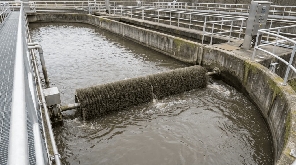
Characterized by a closed-loop channel, often in a racetrack or oval configuration, the oxidation ditch relies on mechanical aeration equipment to provide both oxygen for biological metabolism and channel velocity to keep solids in suspension. The extended aeration typically provided by these systems facilitates not only carbonaceous biochemical oxygen demand removal but also nitrification and, with specific process designs, denitrification and biological phosphorus removal.
For consulting engineers and utility decision-makers, selecting the correct Original Equipment Manufacturer for an oxidation ditch system is not merely a matter of procuring hardware. It involves selecting a proprietary process technology that dictates civil design, hydraulic profiles, energy consumption baselines, and long-term maintenance strategies. Unlike generic pumping or piping systems, oxidation ditches often utilize patented aeration and flow configurations—the brush rotor, the vertical shaft surface aerator, or the rotating disc—that fundamentally alter the plant’s footprint and operational philosophy.
Regulatory drivers, including stringent nutrient limits for total nitrogen and total phosphorus, have pushed the basic oxidation ditch to evolve from a simple aerobic basin into sophisticated phased-isolation or multi-zone reactors. As a variant of the activated sludge family, the oxidation ditch inherits the same biological fundamentals while imposing a distinctive set of hydraulic constraints, principally the requirement to maintain minimum channel velocities, typically around 1.0 ft/s or 0.3 m/s, to prevent mixed liquor suspended solids from settling. This article provides a comprehensive engineering analysis of the leading OEMs in this sector, focusing on technical specifications, process capabilities, and lifecycle considerations.
2. Oxidation Ditch Design, Operation, and Optimization Topics
Equipment selection is one of several decisions that determine whether an oxidation ditch performs. Three others recur across the asset life and are treated in dedicated depth elsewhere: sizing the reactor correctly for the peak condition, diagnosing dissolved oxygen problems once the plant is running, and reducing the energy the aeration system consumes without compromising treatment. Each interacts with the OEM decision, and each is worth settling before or alongside it.
Sizing the Ditch for Peak Load
The reactor volume, channel geometry, and installed aeration capacity all derive from the design load, and the question of how to size an oxidation ditch for peak load is more consequential in this process than in most, because the long solids retention time that gives the oxidation ditch its stability also makes it slow to recover from an undersized condition.
Two peak conditions matter and they are not the same. The peak organic and nitrogenous load determines the oxygen requirement and therefore the installed aeration capacity, and it typically occurs seasonally rather than daily. The peak hydraulic condition determines the detention time actually available and the solids loading imposed on the downstream clarifiers, and it typically occurs during wet weather. A ditch sized on average conditions with a modest factor applied to both will be adequate for neither. The winter nitrification condition deserves particular attention, since nitrifier growth rates fall sharply with temperature and the required aerobic solids retention time can double between summer and winter, which is a volume requirement rather than an aeration requirement.
Troubleshooting Low Dissolved Oxygen
Once the plant is operating, dissolved oxygen is the parameter operators watch most and misdiagnose most often. A structured approach to oxidation ditch troubleshooting for low DO matters because the symptom has at least five distinct causes with different remedies, and the instinctive response of simply increasing aeration addresses only one of them.
The candidate causes are worth holding in mind as a set: an actual increase in load, whether organic, nitrogenous, or from a returned side stream; degraded oxygen transfer from fouled, worn, or incorrectly immersed aeration equipment; probe fouling or drift producing a false reading; inadequate channel velocity allowing solids to deposit and creating localized demand; and a genuine capacity shortfall relative to a load the plant has grown into. Distinguishing among them requires load data, aeration equipment condition, and probe verification together—never a DO reading alone.
Energy Optimization
Aeration dominates the energy bill in any activated sludge plant, and the oxidation ditch is no exception. Approaches to oxidation ditch energy optimization generally rest on control strategy rather than equipment replacement, because the mechanical aerators already installed usually have more turndown available than the plant is using.
The constraint that makes this harder than it appears is that mechanical aeration in a ditch performs two jobs at once. Reducing aerator speed or immersion to save energy also reduces the propulsion that maintains channel velocity, and below a certain point the solids begin to settle. This is the fundamental tension in oxidation ditch energy work, and it is why installations with independent mixing—submersible mixers providing velocity while aerators provide only oxygen—can turn down far further than those relying on the aerator for both functions. Where the aerator does both, the practical energy strategies are dissolved oxygen based control within the mixing floor, immersion depth adjustment through outlet weir control, and taking units out of service in sequence rather than running all of them at reduced output.
3. How to Select This Process Equipment
Selecting an oxidation ditch system requires a multi-disciplinary engineering approach, integrating process biology, hydraulics, and mechanical reliability. The following factors must be evaluated during preliminary design and equipment selection.
Process Function and Performance Requirements
The primary function of the oxidation ditch is to create a stable environment for biomass to degrade organic matter. Engineers must evaluate each OEM’s ability to meet specific effluent limits, particularly for nitrogen.
- Nitrification: Because of large tank volumes and long solids retention times, typically 15 to 30 days, oxidation ditches differ substantially from high-rate activated sludge. Equipment selection must ensure adequate standard oxygen transfer rate to satisfy the nitrogenous oxygen demand alongside carbonaceous demand.
- Denitrification: Modern permits often require total nitrogen removal. Engineers must assess whether the OEM offers discrete anoxic zones or promotes simultaneous nitrification and denitrification. The latter relies on creating anoxic micro-zones within the floc or specific oxygen gradients along the channel, and is heavily influenced by the type of aerator selected.
- Biological Phosphorus Removal: If biological phosphorus removal is required, the design must include an anaerobic selector zone upstream of the ditch, integrated with the return activated sludge line.
- Process Parameters: The operating targets that govern performance—MLSS, MLVSS, food-to-microorganism ratio, and solids retention time—are the same as in any activated sludge system, and the relationships among activated sludge parameters determine the reactor volume that any manufacturer’s equipment must be sized to serve.
Hydraulics and Channel Velocity
A defining characteristic of the oxidation ditch is horizontal velocity. The aeration device must impart enough momentum to the liquid to maintain a velocity of roughly 0.8 to 1.2 ft/s throughout the entire channel cross-section.
- Propulsion Efficiency: Some aerators are excellent at oxygen transfer but poor at propulsion, and the reverse also occurs. Engineers must calculate the hydraulic energy required to overcome channel friction and head loss through bends, separately from the oxygen calculation.
- Depth Limitations: Horizontal brush rotors typically limit channel depth to roughly 8 to 12 feet. Vertical shaft aerators allow considerably deeper tanks, on the order of 12 to 20 feet or more, which can significantly reduce the civil footprint.
- Baffle Walls: Flow directional baffles or turning vanes are often required to minimize head loss at channel turns and prevent dead zones where solids accumulate and go septic.
Materials of Construction
Oxidation ditch equipment operates continuously in a corrosive, wet environment. Material selection dictates the longevity of the installation.
- Rotors and Discs: Shafts should be carbon steel with robust epoxy coatings, or stainless steel. Blades and discs are often molded high-density polyethylene or fiberglass-reinforced plastic to resist UV degradation and chemical attack.
- Splash Covers: To control aerosols and odor, and to prevent freezing in cold climates, covers are essential. These are usually fabricated from FRP or aluminum.
- Bearings: This is the most critical mechanical component on rotor systems. Outboard bearings must be heavy-duty pillow-block style with straightforward access for lubrication.
Energy Efficiency and Operating Cost
Aeration commonly accounts for roughly half to two-thirds of a wastewater plant’s energy usage. In oxidation ditches, efficiency is measured as standard aeration efficiency, typically expressed in pounds of O2 per horsepower-hour.
- Turndown Capability: Influent loads vary diurnally. The equipment must be able to reduce oxygen delivery without compromising mixing velocity. Variable frequency drives are standard, but mechanical aerators have a lower speed limit, frequently around 50 to 60 percent, below which mixing fails.
- Submergence Control: Some systems use automated adjustable outlet weirs to change rotor immersion depth, allowing oxygen transfer adjustment independent of motor speed.
Operations and Maintenance Impacts
The physical layout of an oxidation ditch has a substantial effect on operations and maintenance.
- Access: Engineers must design walkways and platforms that allow safe access to drive units and bearings.
- Winter Operation: In northern climates, surface aerators cause significant heat loss and icing. Covers or housing structures are effectively mandatory to prevent ice buildup on rotor blades, which causes imbalance and destructive vibration.
- Aerosols: Surface aeration generates mist that can carry pathogens. Site layout must consider prevailing winds and proximity to neighbors or plant staff working areas.
Lifecycle Cost Considerations
While surface aeration oxidation ditches generally carry lower capital cost than diffused air systems because they avoid blowers and piping grids, the lifecycle analysis must account for several items.
- Gearbox Replacement: Vertical shaft aerators rely on large reduction gearboxes that require periodic overhaul or replacement, commonly on a 10 to 15 year interval.
- Civil Costs: Shallow ditches require large land areas. Deep ditches require more expensive excavation and concrete work.
- Servicing Access: Unlike diffused air systems that require tank draining to replace membranes every 7 to 10 years, surface aerators can often be serviced from the bridge, though complete removal usually requires a crane.
4. Selection & Specification Framework
The criteria above are individually familiar. Poor outcomes generally come from sequencing them badly—typically by selecting a proprietary technology on capital cost or precedent, then designing the civil works around it and discovering the process or hydraulic consequences during startup.
Step 1: Fix the Effluent Requirement Before the Technology
State the permit limits, including any seasonal variation, and determine whether the process must achieve carbonaceous removal only, nitrification, total nitrogen removal, or biological phosphorus removal. Each step up this ladder narrows the technology field, because the geometries and aeration methods that support simultaneous nitrification and denitrification differ from those optimized purely for oxygen transfer. Deciding this first prevents the common outcome of retrofitting anoxic zones into a basin that was never laid out for them.
Step 2: Establish the Design Temperature and the Winter SRT
Nitrifier growth rate falls sharply with temperature, so the aerobic solids retention time required for reliable nitrification in winter can be roughly double the summer figure. Because reactor volume follows from SRT, the winter condition usually sets the tank size while the summer condition sets the peak oxygen demand. Confirm which governs before sizing anything, and state the design minimum temperature explicitly in the basis of design.
Step 3: Worked Volume and Channel Velocity Example
Consider a 2 MGD plant with an influent BOD of 220 mg/L and total Kjeldahl nitrogen of 35 mg/L, designing for reliable nitrification at a minimum liquid temperature of 12 degrees Celsius. At that temperature a design aerobic solids retention time in the region of 12 to 15 days is typical, and with an extended aeration mixed liquor concentration around 3,500 mg/L, the required reactor volume works out in the vicinity of 1.6 to 2.0 million gallons, or roughly 215,000 to 270,000 cubic feet. At 12 feet of side water depth, that implies a channel cross-section and length combination on the order of 18,000 to 22,000 square feet of surface area.
Now check the hydraulic side, which is where oxidation ditch designs most often go wrong. If the channel is 20 feet wide at 12 feet deep, the cross-sectional area is 240 square feet. Maintaining 1.0 ft/s of channel velocity therefore requires a circulating flow of 240 cubic feet per second—approximately 108,000 gallons per minute, or about 155 MGD of internal circulation. That is roughly 78 times the plant’s forward flow, and it illustrates why propulsion, not treatment flow, sizes the aeration equipment’s hydraulic duty. An aerator selected purely on oxygen transfer, without checking that it can move this circulating volume against channel friction and bend losses, will produce a ditch that treats adequately at design load and deposits solids in the channel bottom whenever the aerators turn down.
Step 4: Verify That Oxygen and Mixing Turndown Are Compatible
Establish the minimum aeration output required for mixing and the minimum required for oxygen at the lowest expected load, and confirm the two are compatible. Where the mixing floor exceeds the oxygen requirement at night or in low season, the plant will over-aerate to keep solids suspended, wasting energy and potentially suppressing denitrification. In that situation, independent submersible mixers are worth pricing, because they decouple the two functions and unlock turndown that no control strategy can otherwise reach.
Step 5: Specify Civil Tolerances With the Equipment
Brush rotors and disc aerators are unusually sensitive to concrete accuracy, because immersion depth varies directly with any deviation in wall parallelism or floor level. State the required tolerances in the civil specification and make the equipment supplier’s dimensional requirements a coordination deliverable, not something resolved during construction.
Step 6: Compare on Twenty-Year Cost Including Civil Works
Build the comparison from installed equipment cost, the civil cost implied by the depth and footprint each technology requires, aeration energy at the actual load profile rather than at design, gearbox or bearing overhaul cycles, and the cost of covers, screening, and other supporting provisions each technology imposes. A deep vertical-aerator ditch and a shallow rotor ditch can have similar equipment costs and very different total project costs once excavation, concrete, and land are counted.
5. Comparison Tables
The following tables compare the leading OEMs and the underlying aeration technologies. Engineers should use Table 1 to align project constraints—land availability, nutrient limits, and maintenance capability—with each manufacturer’s design philosophy, and Table 2 to settle the technology family before comparing suppliers.
| OEM Name | Core Technology | Engineering Strengths | Limitations | Best-Fit Scenarios |
|---|---|---|---|---|
| Lakeside Equipment | Horizontal brush rotor | Simplicity of design; high propulsion efficiency; proven longevity; accessible maintenance. | Shallow depth requirement increases land use; aerosol generation; heat loss in winter. | Small to mid-sized municipalities with available land; plants requiring robust, simple mechanicals. |
| Evoqua (Xylem) | Disc aeration in concentric channels; vertical loop reactor | Simultaneous nitrification and denitrification via oxygen layering; series operation; resistance to clogging. | Large footprint for the concentric configuration; complex concrete forming; proprietary disc elements. | Projects with strict total nitrogen limits; facilities requiring process stability under varying loads. |
| Ovivo | Vertical shaft surface aerator in a looped channel | Deep tank capability with small footprint; efficient vertical aeration; strong mixing energy. | Requires large gearboxes and bridge infrastructure; discrete anoxic zones often needed for low TN. | Land-constrained sites; larger municipal plants; deep excavation scenarios. |
| WesTech Engineering | Slow-speed vertical surface aeration; drum aerator systems | Low-shear aeration; drum designs provide efficient mixing at low energy; heavy-duty drive assemblies. | Proprietary drum mechanisms may require specialized maintenance; drive assemblies are more complex. | Industrial wastewater; municipal plants prioritizing energy efficiency and durable mechanics. |
| Aero-Mod | Integrated clarification within the process train | Eliminates external clarifiers and RAS pumping; batch-like performance in flow-through mode. | Higher process control complexity; dependent on proprietary internal geometry. | Small to medium plants wanting a compact all-in-one nutrient removal solution. |
| Technology | Typical Channel Depth | Propulsion | Turndown Before Mixing Fails | Winter Vulnerability | Primary Maintenance Item |
|---|---|---|---|---|---|
| Horizontal Brush Rotor | 8–12 ft | Excellent; direct horizontal thrust | Moderate; immersion adjustment extends range | High; icing on blades causes imbalance | Outboard bearings and seals |
| Rotating Disc | 8–14 ft | Good; supports oxygen layering along the channel | Moderate to good | Moderate to high; covers advisable | Disc elements and shaft bearings |
| Vertical Shaft Surface Aerator | 12–20+ ft | Strong; pumps from the floor across the surface | Limited; mixing floor is relatively high | Moderate; spray and heat loss | Reduction gearbox |
| Submerged Mixer plus Separate Aeration | Any | Independent of aeration output | Excellent; functions are decoupled | Low; no surface spray | Mixer seals and, if diffused, membranes |
| Drum Aerator | 10–16 ft | Good; low-shear surface entrainment | Moderate | Moderate | Drum elements and drive assembly |
6. Top OEM Manufacturers
The following manufacturers are among the established suppliers of oxidation ditch technologies. Selection should be based on the compatibility of their proprietary aeration and flow configurations with the project’s biological and hydraulic goals.
Lakeside Equipment Corporation
Lakeside Equipment has a long history in the oxidation ditch market and was influential in establishing the technology in the United States. Their core offering centers on a horizontal brush aerator.
- Technology Description: The rotor consists of a horizontal shaft with die-formed steel blades. As it spins, it impacts the water surface to introduce oxygen while simultaneously pushing water to create channel velocity. The design is mechanically simple, relying on a motor, gear reducer, and horizontal bearings.
- Engineering Advantage: The principal advantage is process stability in a closed loop reactor configuration. The rotors provide aggressive mixing, ensuring solids do not settle. Maintenance is straightforward because moving parts are accessible from the bridge surface without cranes or tank draining.
- Process Considerations: Designs often use adjustable effluent weirs to control rotor immersion, letting operators match oxygen transfer to influent load without changing rotor speed, though variable speed drives are now common. This flexibility helps maintain process stability during the low-flow early years of a plant’s life.
Evoqua (Xylem)
Evoqua, now part of Xylem, offers a widely installed concentric-channel disc aeration system and a vertical loop reactor configuration. The concentric system is distinctive in both geometry and aeration method.
- Technology Description: The system typically features concentric channels, usually three, operating in series. The outer channel is aerated to operate in an oxygen-deficit mode, the middle channel is a transition zone, and the inner channel acts as a polishing step. Aeration is provided by rotating discs rather than bladed rotors.
- Engineering Advantage: The disc design introduces oxygen in a manner that creates layered aerobic and anoxic conditions within the same channel depth, facilitating simultaneous nitrification and denitrification. The concentric arrangement provides a built-in step-feed effect and buffers the system against hydraulic shock loads.
- Process Considerations: For sites with limited footprint, the vertical loop reactor reorients the concept into deep tanks, using surface discs or diffused air to achieve comparable results in a smaller area.
Ovivo
Ovivo markets a looped-channel system that is fundamentally different from horizontal rotor designs in that it uses vertical shaft surface aerators. The technology is among the most widely installed oxidation ditch configurations globally.
- Technology Description: The design places a low-speed vertical shaft aerator at the turn of the channel. This aerator draws liquid from the bottom of the tank and throws it outward across the surface, providing both oxygen transfer and significant hydraulic propulsion.
- Engineering Advantage: The vertical pumping action allows operation at depths of 12 to 20 feet or more, substantially deeper than brush rotor ditches, which reduces the surface area required. Anoxic zone modifications with a dedicated mixer allow controlled denitrification and total nitrogen removal.
- Process Considerations: The hydraulic radius of influence of the aerator dictates the channel width. Engineers must size the aerator not only for oxygen but for the hydraulic thrust required to maintain velocity through the entire loop.
WesTech Engineering
WesTech provides oxidation ditch solutions with an emphasis on robust mechanical design and energy efficiency, offering both vertical shaft surface aeration and drum aerator systems.
- Technology Description: Their vertical shaft system is a low-speed surface aerator design optimized for mixing efficiency. The drum system uses a drum-style mixer and aerator that partially separates the mixing function from aeration, or uses specific drum geometries to maximize interfacial contact.
- Engineering Advantage: WesTech is noted for heavy-duty drive assemblies and gearboxes designed for long life. The drum system is particularly effective in industrial applications or high-strength waste scenarios where oxygen transfer efficiency and mixing reliability are paramount.
- Process Considerations: Their systems are highly customizable and can be configured for flow-through or semi-batch operation. The emphasis on slow-speed aeration minimizes shearing of the biological floc, which can improve settling characteristics in the downstream secondary clarifiers.
Aero-Mod
Aero-Mod distinguishes itself with process configurations that integrate clarification directly into the treatment train, eliminating the need for traditional external circular clarifiers.
- Technology Description: The approach combines aeration with a clarification geometry located within the same structure, using specific hydraulic principles to settle solids and return them to the aeration zone.
- Engineering Advantage: The primary benefit is elimination of separate return activated sludge pumping stations and external clarifier mechanisms. This simplifies the hydraulic profile and reduces total plant footprint and concrete cost.
- Process Considerations: The configuration suits batch-like performance in a continuous flow regime and handles peak flows well because of integrated surge capacity. However, the design requires operators to be trained specifically on its process control philosophy, which differs from standard flow-through ditches.
7. Application Fit Guidance
Choosing the right OEM often depends on facility size, wastewater characteristics, and site constraints.
Municipal Wastewater (Small to Mid-Sized)
For communities from roughly 0.5 to 5 MGD, Lakeside and Aero-Mod are frequently preferred. Brush rotors are straightforward for small staffs to maintain, with no complex hydraulics or submerged servicing, while Aero-Mod offers a compact solution that reduces civil work by eliminating external clarifiers.
Municipal Wastewater (Mid to Large)
For facilities above roughly 5 MGD, or where land costs are high, Ovivo and Evoqua are strongly represented. The deep tank design minimizes land usage, and the concentric channel arrangement is frequently selected when stringent total nitrogen limits apply, since its series operation supports nutrient removal without complex internal recycle pumping.
Industrial Wastewater
WesTech and Ovivo are strong contenders here. Industrial waste often involves higher strength variations and potential toxicity. The mixing energy of vertical shaft aerators ensures complete suspension of heavier industrial solids and provides aggressive oxygen transfer for high-BOD loads.
Retrofit vs. Greenfield
For retrofitting existing lagoons or shallow basins, Lakeside rotor systems suit the available depth. For greenfield projects on restricted sites, Ovivo or the Evoqua vertical loop configuration are preferred for their vertical use of space.
Operator Capability as a Selection Criterion
Oxidation ditches are frequently chosen for small plants precisely because they are forgiving, and that reasoning should extend to the equipment selection. A configuration requiring active management of multiple zones, internal recycle rates, and a distinctive control philosophy will outperform a simple ditch when it is well run, and underperform it when it is not. Where the plant has one or two operators covering multiple facilities, weight simplicity and accessible mechanicals heavily. The broader principles of running these systems well are common across the family, and grounding staff in the activated sludge process fundamentals matters more to long-run performance than the specific proprietary geometry selected.
8. Engineer & Operator Considerations
Beyond process selection, successful implementation relies on detailed attention to installation and long-term maintainability.
Installation and Commissioning
Concrete Tolerance: Oxidation ditch aerators, particularly brush rotors and discs, require tight concrete tolerances. If the channel walls are not parallel or the floor is not level, rotor immersion depth varies along its length, causing uneven drive loading and poor process performance. Engineers must specify strict tolerances in the civil documents.
Clean Water Testing: Specifying clean water oxygen transfer testing as part of commissioning is strongly advisable to verify the manufacturer’s stated transfer rate before biology is introduced, since it is the only point at which the equipment can be assessed against a repeatable standard.
Maintenance Access
Bridge Design: Bridges spanning the ditch must be designed not merely for foot traffic but for maintenance loads. Can a small crane or forklift reach the drive unit? Is there laydown space for a removed motor or gearbox?
Lubrication: Automated greasing systems are advisable for outboard bearings on rotor systems, since these are frequently located in positions that are awkward and unsafe to reach over open water.
Operational Lessons Learned
Icing: In freezing climates, uncovered rotors effectively become snow-making machines. Ice buildup causes imbalance and gearbox failure. Engineers must specify insulated, heat-traced, or robust FRP covers for rotors in northern regions.
Ragging: While oxidation ditches are generally resistant to clogging, aeration rotors and vertical shafts can accumulate rags where upstream screening is inadequate. Fine screening at 6 mm or below is advisable upstream of any mechanical aeration device.
Long-Term Reliability Risks
The gearbox is the weak link in vertical shaft systems. Specify a minimum service factor, commonly 2.0 or higher, for gear reducers to handle the shock loads of starting and stopping large aerators. For horizontal rotors, the primary risk is bearing failure from seal degradation and water intrusion; triple-lip or purgeable seal arrangements are advisable, together with a documented lubrication routine that is actually achievable given the access provided.
9. Design Details & Standards
Applicable Standards and References
Oxidation ditch design commonly references Ten States Standards (Recommended Standards for Wastewater Facilities) for aeration basin criteria, solids retention time, and oxygen requirements, together with the WEF Manual of Practice No. 8 / ASCE MOP 76 for process design methodology and WEF MOP No. 11 for operation. Clean water oxygen transfer testing follows ASCE/EWRI 2-06, with in-process verification per ASCE 18-96 where site testing is required. Gearbox ratings and service factors follow AGMA standards with the basis stated. Motors follow NEMA MG-1, with Part 31 applicable to inverter-duty machines on variable speed drives. Electrical area classification over open basins and in adjacent structures follows NFPA 820 together with NFPA 70. Structural design of bridges and walkways follows AISC provisions, with concrete to ACI 318 and tolerances to ACI 117, which is the standard to cite when specifying the channel accuracy these aerators require. Rotating equipment guarding is governed by OSHA 29 CFR 1910.212 and fall protection by 29 CFR 1910.28.
Specification Checklist
- Design Basis: Flow at average and peak, influent BOD and TKN, design minimum and maximum liquid temperature, and the effluent limits including any seasonal variation.
- Process Requirements: Required solids retention time at the design minimum temperature, target MLSS, and whether nitrification, denitrification, or biological phosphorus removal is required.
- Oxygen Requirement: Actual oxygen requirement at peak load with the alpha, beta, and temperature correction basis stated, converted to a standard oxygen requirement for equipment selection.
- Hydraulic Requirement: Required channel velocity, channel cross-sectional area, the resulting circulating flow, and the head loss allowance for channel friction and bends.
- Turndown: Minimum aeration output for oxygen at low load, minimum output for mixing, and confirmation that the two are compatible across the operating range.
- Equipment: Aerator type, quantity, immersion adjustment method, drive rating, gearbox service factor with AGMA basis, and bearing arrangement and seal type.
- Materials: Shaft, blade or disc, and fastener materials, with coating systems specified where carbon steel is used.
- Civil Coordination: Channel dimensional tolerances referencing ACI 117, baffle and turning vane arrangement, and anchor bolt and grouting requirements.
- Covers and Enclosure: Cover requirement and material for aerosol, odor, and freeze protection, with heat tracing where applicable.
- Access: Bridge and walkway design loads, crane or hoist provisions, laydown space, lubrication access, and fall protection.
- Controls: Dissolved oxygen instrumentation and location, speed and weir control strategy, alarms, interlocks, and the SCADA signal list.
- Testing: Clean water oxygen transfer test requirement, channel velocity verification at defined locations and depths, and vibration baseline at commissioning.
10. Frequently Asked Questions
What makes an oxidation ditch different from conventional activated sludge?
Principally the solids retention time and the reactor geometry. Oxidation ditches operate in the extended aeration range, commonly 15 to 30 days of solids retention, which produces a stable, well-nitrified, low-yield process that tolerates shock loads well and generates less waste sludge per unit of BOD removed. The closed-loop channel geometry means the contents circulate many times before leaving, giving near-complete-mix behavior with a plug-flow character around the loop. The trade-off is a much larger reactor volume than a high-rate process would require.
What channel velocity is required and why does it matter?
A velocity of roughly 0.8 to 1.2 ft/s throughout the channel cross-section is the conventional requirement, with 1.0 ft/s a common design target. Below that range mixed liquor solids begin to deposit on the channel floor, particularly in the bends and on the far side of the loop from the aeration equipment. Deposited solids go anaerobic, create localized oxygen demand, reduce effective reactor volume, and eventually require the basin to be taken out of service and cleaned. The velocity requirement, not the oxygen requirement, frequently sets the minimum aeration output.
How deep can an oxidation ditch be?
Depth is set by the aeration technology. Horizontal brush rotors are generally limited to around 8 to 12 feet, because their influence does not extend reliably deeper and solids deposit below the mixed zone. Vertical shaft surface aerators pump from the floor upward and support depths of 12 to 20 feet or more. Deeper basins reduce land requirement substantially but increase excavation and concrete cost, so the comparison is a total project cost question rather than an equipment question.
Can an oxidation ditch achieve total nitrogen removal?
Yes, by two broad routes. Discrete anoxic zones with controlled internal recycle provide conventional denitrification and give the operator direct control. Simultaneous nitrification and denitrification relies on maintaining oxygen gradients along the channel or within the floc so that both reactions proceed in the same volume, and it can be very effective but is more sensitive to load and dissolved oxygen control. Which route suits a given plant depends on the permit limit, the operator capability, and whether the geometry supports controlled zoning.
What causes low dissolved oxygen in an oxidation ditch?
At least five distinct causes, which is why the symptom is so often misdiagnosed. An actual load increase, whether organic, nitrogenous, or from a recycled side stream. Degraded oxygen transfer from worn, fouled, or incorrectly immersed aeration equipment. Probe fouling or calibration drift producing a false reading. Inadequate channel velocity allowing solids to deposit and create localized demand. And a genuine capacity shortfall relative to a load the plant has grown into. Diagnosis requires load data, equipment condition, and probe verification together; simply raising the aeration setpoint addresses only one of the five.
How much energy does an oxidation ditch use, and where can it be reduced?
Aeration typically dominates plant energy consumption. The reduction opportunities in a ditch are mostly in control rather than hardware: dissolved oxygen based speed control operating down to the mixing floor, immersion depth adjustment through outlet weir control, and sequencing units out of service rather than running all of them at partial output. The constraint is that mechanical aeration provides both oxygen and propulsion, so turndown is bounded by the mixing requirement. Installations with independent submersible mixers can turn aeration down considerably further because the two functions are decoupled.
What are the main winter operating challenges?
Three, and they compound. Nitrifier growth rate falls sharply with temperature, so the required aerobic solids retention time rises and a basin adequate in summer may not nitrify reliably in winter. Surface aeration causes heat loss, accelerating the temperature drop that created the problem. And ice accumulation on rotor blades or aerator components causes imbalance that damages bearings and gearboxes. Covers address the second and third; the first has to be addressed in the reactor volume at design time.
What upstream screening does an oxidation ditch require?
Finer than many operators expect. While the process itself is tolerant, rotors, discs, and vertical shafts accumulate rags, and material that wraps a rotating element causes imbalance rather than simply reducing performance. Screening at 6 mm or finer upstream of any mechanical aeration device is advisable, and perforated plate is preferable to bar screening at equivalent nominal opening because it prevents fibrous material from passing through lengthwise.
11. Conclusion
Key Takeaways
- Winter sets the volume, summer sets the aeration — the required aerobic solids retention time can roughly double between summer and winter, and that is a reactor volume requirement no amount of installed aeration capacity resolves.
- Propulsion sizes the equipment, not just oxygen — the circulating flow needed to hold 1.0 ft/s can be dozens of times the plant’s forward flow, and an aerator adequate for oxygen may fall well short of the required thrust.
- Check that oxygen and mixing turndown are compatible — where the mixing floor exceeds the low-load oxygen requirement, the plant over-aerates to keep solids suspended and independent mixers become worth pricing.
- Depth is a technology decision with civil consequences — brush rotors constrain depth and consume land; vertical aerators permit deep basins at higher excavation and gearbox cost.
- Concrete tolerance is a process requirement — immersion depth varies directly with wall parallelism and floor level, so specify tolerances explicitly rather than leaving them to general civil practice.
- Low DO has five common causes — raising the aeration setpoint addresses only one of them, and diagnosis needs load, equipment condition, and probe verification together.
- Match complexity to operator capability — a sophisticated multi-zone configuration outperforms a simple ditch when well run and underperforms it when not, which matters most at the small plants this process typically serves.
The oxidation ditch remains a workhorse of the wastewater treatment industry, offering a balance of process stability and nutrient removal capability. However, the category is not monolithic; the choice among horizontal rotors, rotating discs, vertical impellers, and integrated clarification configurations fundamentally changes the plant design.
Engineers must look beyond the capital cost of the equipment and evaluate the civil construction implications of depth versus area, the energy lifecycle through aeration efficiency and turndown, and the maintenance reality of gearbox versus bearing accessibility. By aligning the specific biological requirements—particularly nitrogen targets and the winter condition that governs them—with the mixing and aeration physics of these OEMs, utilities can secure a resilient treatment system with a service life exceeding twenty years.