
Top OEMs for Pressure Release Valves
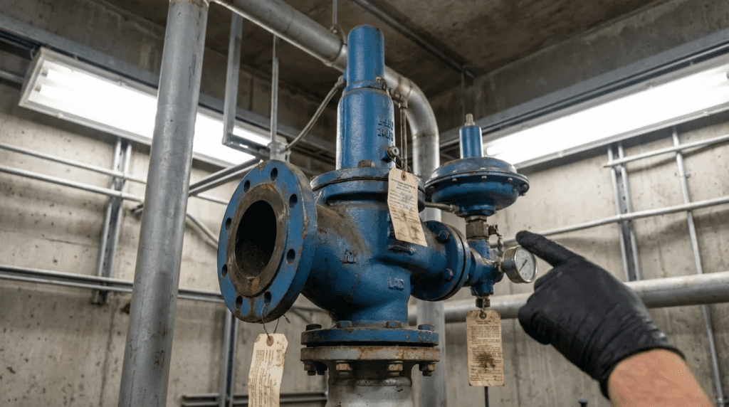
1. Introduction
In the context of municipal and industrial water and wastewater systems, the term “Pressure Release Valve” (PRV) encompasses a critical range of safety and control devices designed to protect infrastructure from catastrophic over-pressure events. These devices function as the final line of defense against hydraulic transients (surge), pump malfunctions, thermal expansion, and process control failures. For the consulting engineer and plant superintendent, the selection of a PRV is rarely a matter of simple commodity specification; it is a risk management decision that directly impacts the safety of personnel, the longevity of piping networks, and regulatory compliance.
The scope of pressure release applications in water and wastewater treatment plants is bifurcated into two distinct engineering categories. First, Hydraulic Surge Relief involves protecting distribution networks and force mains from the destructive forces of water hammer caused by pump trips or rapid valve closures. These valves must react quickly to discharge fluid and dampen pressure waves. Second, Process Safety Relief involves ASME-coded protection for pressurized vessels, chemical storage tanks, aeration blowers, and steam lines within the plant facility.
Regulatory context plays a significant role in OEM selection. Applications involving pressurized vessels must adhere to ASME Boiler and Pressure Vessel Code Section VIII, while potable water applications often require NSF/ANSI 61 and 372 certification. Furthermore, a pressure release valve may remain static for months or years, yet must operate within strict tolerances the instant a system upset occurs. This dormant reliability is the primary driver for prioritizing established manufacturers with verifiable engineering pedigrees.
This article provides a technical analysis of the selection criteria, failure modes, and operational characteristics of these valves, followed by a review of four specific OEMs: Anderson Greenwood, Crosby Valve, Penn-Troy Manufacturing, and GA Industries. It sits within our coverage of pressure relief valve manufacturers.
A note on terminology: the standard industry terms are pressure relief valve, safety relief valve and surge relief valve; “pressure release valve” is a colloquialism and does not appear in ASME or AWWA language. Specifications should use the code terminology, since the distinction between a relief valve, a safety valve and a surge anticipator changes which standard applies and what the manufacturer must certify.
Manufacturer ownership in this segment has changed repeatedly through acquisition. Confirm current ownership, brand continuity and product availability with the manufacturer or its representative before writing any of these names into a specification.
2. How to Select This Valve Type
Valve Function and Duty Cycle
The first step is defining the nature of the over-pressure scenario. Is the valve intended for Safety Relief, preventing a vessel from rupturing, or Surge Relief, preventing a pipe from bursting due to a transient wave?
- Direct Spring-Loaded vs. Pilot-Operated: For standard safety relief, direct spring valves offer simplicity and fail-safe operation. However, as system pressure approaches the set pressure, spring valves can simmer or leak. Pilot-operated relief valves utilize system pressure to seal the valve tighter as pressure increases, making them superior for operating pressures close to the set limit.
- Modulating vs. Pop-Action: In liquid applications, a pop-action valve can exacerbate water hammer by closing too instantly. Modulating pilots that open in proportion to the over-pressure are often preferred to maintain system stability.
Pressure and Flow Conditions
- Set Pressure and Accumulation: The engineer must define the set pressure, where the valve starts to open, and the allowable accumulation, the pressure rise over the set pressure during discharge, typically 10% or 21% depending on the code case.
- Blowdown: The difference between set pressure and reseating pressure. In water systems, a long blowdown is often desirable to dissipate energy; in steam or gas, short blowdown preserves process media.
- Flow Capacity: Sizing must account for the worst-case scenario, such as total pump runout or full thermal expansion.
Materials of Construction
- Body Materials: Ductile iron (ASTM A536) is standard for general water. Stainless steel or exotic alloys are mandatory for corrosive chemical feed systems such as sodium hypochlorite or ferric chloride.
- Trim and Seats: Hardened stainless steel trim resists wire-drawing, the erosion of the seat during initial opening. For dirty services like raw sewage, soft-seated valves typically provide better shut-off but require more frequent maintenance.
Sealing Mechanisms and Actuation
- Filtration: For wastewater surge relief, non-clogging pilot designs or heavy-duty external strainers are prerequisites, since a clogged sensing line can prevent the valve from opening or closing.
- Diaphragm vs. Piston: Diaphragm actuators generally have lower friction and better responsiveness for low-pressure variations but lower pressure ratings. Piston actuators are robust and handle higher pressures but have higher friction.
Installation Environment
- Vault Drainage: Relief valves discharge fluid. If the vault lacks adequate drainage or sump capacity, the valve can become submerged, creating a cross-connection risk through the discharge port.
- Freezing: In cold climates, pilot lines containing static water are prone to freezing. Heat tracing, insulation, or climate-controlled housing is necessary.
Maintenance and Common Failure Modes
- Seat Leakage: Causes continuous water loss and seat erosion.
- Chatter: Caused by excessive inlet pressure drop or oversizing, leading to rapid mechanical failure. The 3% inlet loss limit discussed below is the usual design control on this.
- Failure to Reseat: The most common failure mode in dirty service, caused by debris entrapment or seat erosion, and the reason strainers and non-clogging pilots matter more in wastewater than the valve body material does.
- Diaphragm Fatigue: In pilot valves, rubber components degrade over time and require a defined replacement schedule, typically every 3-5 years.
3. Comparison Table
| OEM Name | Core Technology Focus | Typical Applications | Primary Engineering Strengths | Maintenance Profile |
|---|---|---|---|---|
| Anderson Greenwood (Emerson) | Pilot-operated safety relief valves and high-performance pilots | High-pressure transmission mains, industrial treatment processes, compressible gas systems. | Exceptional seat tightness near set pressure; modulating action prevents water hammer; suitable for high back-pressure applications. | Specialized skill required for pilot calibration; intolerant of heavy solids without filtration. |
| Crosby Valve (Emerson) | Direct spring-loaded safety relief valves | Boilers, steam lines, chemical feed piping, air receiver tanks, thermal relief. | Industry standard for ASME Section VIII compliance; robust mechanical design; wide range of chemical-compatible materials. | Simple mechanics but prone to simmering near set pressure; set pressure can drift over time. |
| Penn-Troy Manufacturing | Explosion relief and specialized check/relief hybrids | Biogas engine protection, generator sets, pump station air intake and relief. | Established in crankcase explosion relief for engines, critical for cogeneration and biogas facilities. | Highly specialized; internal flame traps require periodic inspection and cleaning. |
| GA Industries | Hydraulic surge relief and automatic control valves | Raw sewage force mains, potable water distribution surge protection, pump station discharge. | Specifically engineered for water hammer; surge anticipation capabilities; designs available for heavy slurry and wastewater. | Designed for field serviceability; pilots require regular cleaning in sewage service. |
4. Top OEM Manufacturers
Anderson Greenwood (Emerson)
Anderson Greenwood is technically distinct in the pressure relief market for its work in pilot-operated safety relief valves. While traditional spring-loaded valves rely on the force of the fluid to overcome a spring, these valves utilize system pressure to hold the seat closed. Sealing force increases as the system pressure approaches the set point, maintaining tightness far closer to set pressure than a spring valve.
Engineering Focus: For the municipal engineer, this is the primary choice for applications requiring high precision and maximum operating pressure efficiency. In water transmission mains where operating pressures are high and margins are thin, the pop action of a standard valve is undesirable. Modulating pilots open the main valve only enough to relieve the required flow, preventing secondary pressure surges caused by the relief valve itself snapping shut.
Key Technologies: Non-flowing pilot designs are critical when the process fluid contains minor particulates, as they reduce the risk of pilot clogging. These valves also suit applications with high variable back-pressure, as the pilot reference is isolated from the discharge header pressure.
Limitations: The complexity of the pilot mechanism requires a higher tier of maintenance capability. They are generally not recommended for raw sewage or sludge applications where heavy solids could bridge the pilot sensing lines.
Crosby Valve (Emerson)
Crosby Valve represents a long-established line of direct spring-loaded pressure relief valves. These are mechanical, relying on a calibrated spring to oppose the system pressure, and are common in industrial settings and the auxiliary systems of water and wastewater plants.
Engineering Focus: Crosby is typically specified for process safety rather than hydraulic surge: boiler protection, compressed air receivers, and chemical storage tanks, with ASME Boiler and Pressure Vessel Code Section VIII certification.
Key Technologies: Material versatility is a strength. For chemical feed systems handling aggressive media, valves with exotic wetted parts and specialized soft seats ensure chemical resistance and tight shutoff.
Limitations: Direct spring valves are susceptible to chatter if the inlet piping causes a pressure drop greater than 3% of the set pressure. They are also prone to simmer as system pressure approaches the set point, and are generally not used for hydraulic surge relief in large water mains due to slower response and no surge anticipation capability.
Penn-Troy Manufacturing
Penn-Troy occupies a specialized niche. In the context of a modern water pollution control plant, its relevance is to power generation and safety infrastructure rather than to the hydraulic network.
Engineering Focus: The primary application is protection of large internal combustion engines and compressors. Wastewater plants frequently utilize large diesel generators for backup power or biogas-fired cogeneration engines. These engines require crankcase explosion relief valves to protect personnel and equipment from deflagrations.
Key Technologies: Crankcase relief valves incorporate an internal flame trap that prevents the ejection of flames into the plant environment during an explosion, a vital safety feature in enclosed plant rooms.
Limitations: This is not a generalist manufacturer for water main surge relief. Specify it for engine safety and specialized air handling protection rather than general hydraulic relief.
GA Industries
GA Industries is a long-established name in municipal water and wastewater hydraulics, with valves engineered specifically for the hydrodynamics of water and sewage rather than adapted from oil and gas practice.
Engineering Focus: This is the primary selection for hydraulic surge relief. The valves sit dormant on a tee connection off a main line and open when a high-pressure transient is detected. They are used in raw sewage lift stations and potable water booster stations.
Key Technologies: Surge anticipator valves are a distinct engineering advantage. Standard relief valves open only after pressure rises; surge anticipators can be configured to open on the down-surge caused by a pump trip, preparing the system to vent the returning high-pressure wave before it arrives. Sewage-specific designs feature bodies that resist clogging and allow solids to pass without hanging up the seat.
Limitations: These valves are large, heavy, and require significant vault space. The hydraulic pilots use the process water for operation; in raw sewage applications, even with strainers, the pilots require a rigorous preventative maintenance schedule.
5. Application Fit Guidance
Municipal Water Distribution
Preferred: hydraulic surge relief designs. For distribution networks, the priority is handling transients caused by pump cycles. Differential piston designs and surge anticipation logic provide the responsiveness required to dampen water hammer.
Municipal Wastewater (Force Mains)
Preferred: solids-handling surge relief designs. Wastewater presents a unique challenge in solids. Standard relief valves will clog. Angled bodies, solids-handling capability, and pilot systems equipped with isolation membranes or oil cushions prevent sewage from contacting sensitive control surfaces.
Industrial Water and High-Pressure Systems
Preferred: pilot-operated safety relief. In industrial water reuse, desalination, or transmission mains operating at higher pressures, the ability to operate closer to set pressure without leakage maximizes system efficiency.
Chemical Feed and Process Steam
Preferred: direct spring-loaded ASME valves. For chlorination lines, polymer feed, boiler steam, and compressed air, these provide the necessary code compliance and material compatibility. The direct spring design avoids the pilot tubing failure risk.
Power Generation and Safety
Preferred: engine crankcase explosion relief. For backup generators, cogeneration engines running on digester gas, and large compressor crankcases, these address the explosion safety standards required by NFPA and engine manufacturers.
6. Engineer & Operator Considerations
Installation Best Practices
Inlet Piping: A critical engineering error is restricting the inlet to a relief valve. The inlet piping must be at least the same size as the valve inlet. Code generally dictates that non-recoverable pressure losses in the inlet piping should not exceed 3% of the set pressure. Exceeding this causes rapid valve chatter.
Discharge Piping: Discharge piping must be supported independently of the valve. The reaction force of a relieving valve is substantial; if the pipe weight rests on the valve, it can distort the body and cause leakage or binding. For water applications, the discharge must be air-gapped or fitted with a backflow preventer if draining to a common sewer.
Maintenance and Access
Spare Parts Strategy: Operators should maintain a critical spares inventory: diaphragm kits, pilot stems, and soft seat goods for pilot-operated and hydraulic valves; spare springs and gaskets for spring valves.
Testing Protocols: Relief valves are often ignored until they fail. A robust maintenance plan includes bench-testing annually. For large surge valves, exercising the pilot manually to ensure free movement of the main piston is critical, as stagnant pistons can seize due to calcification or corrosion.
Common Specification Mistakes
Oversizing: Engineers often apply a large safety factor, resulting in massive oversizing. A relief valve that is too large will open slightly, relieve pressure instantly, slam shut, and repeat. This chatter destroys the valve. Sizing should be based on precise hydraulic modeling of the worst-case surge or thermal expansion scenario.
Ignoring Back Pressure: In complex plant piping, multiple relief valves may vent to a common header. Engineers must calculate built-up back pressure. If header pressure rises when one valve opens, it can prevent other conventional spring valves from opening. In these scenarios, balanced bellows or pilot-operated valves are required.
7. Conclusion
The selection of pressure relief valves in water and wastewater applications is a bifurcation of discipline. For protection of the hydraulic network against surge and water hammer, fluid-mechanics-focused designs with wastewater compatibility stand out. For protection of pressurized process vessels, chemical systems, and steam loops, ASME-coded spring and pilot-operated valves offer the requisite compliance and material diversity. Engine crankcase explosion relief remains a separate specialist category.
Engineers must resist the temptation to treat these valves as commodities. The cost of a relief valve is negligible compared to the cost of a ruptured force main or a compromised chemical storage tank. By specifying the design that aligns with the specific physics of the application, and by using code terminology rather than colloquial names so that bidders quote the same device, utilities can ensure long-term operational safety and minimize lifecycle costs.