
Top OEMs for Valve-Actuator Adaptation Kits
1. Introduction
In the architecture of municipal and industrial fluid control systems, the interface between the valve and the actuator — commonly referred to as the adaptation kit, mounting kit, or valve automation hardware — is frequently the most overlooked component. While engineers invest significant hours specifying the hydraulic performance of the valve and the torque capabilities of the actuator, the mechanical linkage connecting these two critical assets is often relegated to a secondary consideration or left to the discretion of the integrator.
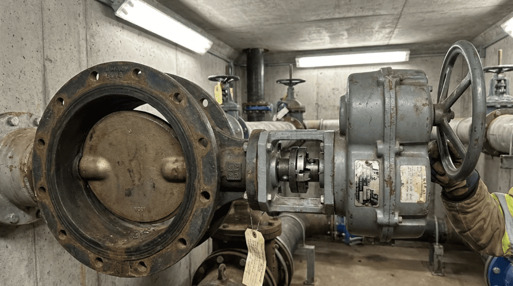
The adaptation kit serves as the critical transmission path for torque and thrust. It consists of the mounting bracket (yoke, spool, or pedestal), the drive coupling (stem extension, drive bush, or coupler), and the associated fasteners. In water and wastewater treatment plants, pump stations, and distribution networks, this hardware must withstand high-cycle fatigue, vibration, thermal expansion, and corrosive environments ranging from submerged pits to chlorine-rich atmospheres.
Failure of the adaptation kit does not merely result in a ceased operation; it can lead to catastrophic damage to the valve stem, destruction of the actuator gear train, or inaccurate process control due to mechanical hysteresis. For consulting engineers and plant superintendents, understanding the engineering pedigree of these kits is essential. The stack — the assembly of valve, kit, and actuator — defines the system’s total reliability.
Regulatory contexts, such as AWWA standards for valve testing and ISO 5210 and 5211 for actuator attachments, provide a framework for design. However, the manufacturing quality, tolerance management, and material selection for these kits vary significantly. This article analyzes the engineering considerations for valve-actuator adaptation kits and evaluates the capabilities of the manufacturers that engineer and supply these critical interfaces.
One clarification, because the original framing was misleading. There is no such thing as an adaptation kit manufacturer as a distinct supplier category. AUMA, Rotork and Limitorque are actuator manufacturers; adaptation hardware is something they supply as part of automating a valve, not a product line they compete in independently. In practice a mounting kit comes from one of three places: the actuator manufacturer, the valve manufacturer, or a machine shop working to dimensions supplied by one of them. Nobody sells adaptation kits as their business.
That distinction matters at specification time. You do not specify an adaptation kit vendor; you assign responsibility for the interface. The article below is therefore best read as guidance on how the three major actuator manufacturers handle the valve interface, and on how to write a specification that keeps the interface from becoming nobody’s problem.
This guide sits within our coverage of adapter and adaptation kit suppliers.
2. How to Select This Hardware
Selecting an adaptation kit is an exercise in mechanical engineering and materials science. The kit must rigidly secure the actuator to the valve bonnet while transmitting rotational or linear force without deflection or slop. Below are the critical engineering criteria for specification and selection.
Torque and Thrust Transmission
The primary function of the adaptation kit is to transmit force. Engineers must verify that the kit is rated for the maximum output torque of the actuator, not just the operating torque of the valve. In a stall condition, an electric actuator can deliver significantly higher torque than required to seat the valve. If the coupling or keyway is undersized, it becomes the mechanical fuse, shearing and rendering the valve inoperable.
For multi-turn applications such as gate and globe valves, the kit must also handle thrust. The thrust base, often integrated into the actuator or the adaptation kit, must absorb the reactionary forces generated when the valve seats. If the adaptation bracket is not designed for this axial load, it can deform, causing misalignment and stem binding.
Alignment and Concentricity
Misalignment is the leading cause of premature packing failure and stem wear. The adaptation kit must ensure concentricity between the actuator output shaft and the valve input shaft.
- Parallel Misalignment: Occurs when the shafts are parallel but offset. This induces severe side-loading on the valve packing and actuator bearings.
- Angular Misalignment: Occurs when the shafts are at an angle to each other. This causes cyclical bending stress on the valve stem, leading to fatigue failure.
High-quality kits utilize machined registers on both the valve and actuator sides to ensure self-alignment. Relying solely on bolt clearance holes for alignment is poor engineering practice and should be rejected in specifications.
Materials of Construction
In water and wastewater environments, material selection is dictated by corrosion resistance and galvanic compatibility.
- Carbon Steel: Common for dry, indoor applications. It must be coated to resist oxidation. However, in damp environments, any breach in the coating leads to rapid corrosion.
- Stainless Steel (304/316): The standard for wastewater, coastal, and submerged applications. While more expensive, it eliminates the lifecycle cost of repainting and corrosion-induced structural failure.
- Fasteners: All mounting hardware should be minimum 316 stainless steel. Anti-seize compounds are mandatory to prevent galling during maintenance.
Drive Coupling Mechanics
The mechanism connecting the shafts varies based on application:
- Keyed Connections: Standard for most applications. Tolerances must be tight to prevent keyway wallowing over time.
- Splined Connections: Preferred for high-torque or high-vibration applications due to better stress distribution.
- Square or Double-D Drives: Common in smaller quarter-turn valves.
- Zero-Backlash Couplings: Essential for modulating control valves. Any play in the coupling translates to a deadband in the control loop, causing the actuator to hunt and prematurely wear out.
Structural Design: Open vs. Enclosed
The physical design of the bracket impacts safety and maintenance.
- Open Design (Pillar/Standoff): Allows easy access to the packing gland for adjustment and leak detection. However, it exposes the moving coupling, presenting a pinch point hazard that requires compliant guarding.
- Enclosed (Spool/Tube) Design: Inherently safer and protects the coupling from environmental debris. However, it can mask packing leaks until they become severe and complicates packing adjustments.
Lifecycle and Maintenance Considerations
A properly designed adaptation kit should be maintenance-free, provided the fasteners remain torqued. However, the design should facilitate valve maintenance. Cartridge-style couplings allow the actuator to be removed without disassembling the coupling from the valve stem, simplifying field service.
3. Comparison Table
The following table outlines how the leading actuator manufacturers approach the mechanical interface between the actuator and the valve. This comparison is intended to help engineers understand their structural philosophies, standard offerings, and suitability for complex retrofits versus standard new installations. It is not a ranking.
| Manufacturer | Core Adaptation Philosophy | Primary Interface Standards | Retrofit Engineering Capability | Key Strengths | Typical Limitation Scenarios |
|---|---|---|---|---|---|
| AUMA | Modular output drive system, Forms A through E | ISO 5210 (multi-turn), ISO 5211 (part-turn) | High. Modular bases adapt to a wide range of valve top works. | Extensive modularity allowing field conversion of output types; standardized flange dimensions globally. | Highly engineered modularity can be complex for inexperienced technicians to specify correctly in the field. |
| Rotork | Integrity management and custom engineering | ISO 5210/5211, MSS SP-101 | Extensive. Dedicated site services division for custom fabrication. | Specialized design for severe service and high-vibration; large database of valve top-works dimensions. | Custom engineered solutions for non-standard valves can have longer lead times than off-the-shelf universal kits. |
| Limitorque (Flowserve) | Direct mount and thrust-base integration | ISO 5210/5211, MSS SP-101 | High. Strong integration with legacy infrastructure. | Robust thrust bases capable of handling extreme stem loads; direct mounting options minimize stack height. | Heavy-duty focus may result in over-engineering for light-duty auxiliary water applications. |
4. Manufacturer Approaches
This section details the specific engineering approaches of three major actuator manufacturers to the valve interface. Their approaches define industry best practice in this area.
AUMA
AUMA is known for a design philosophy centered on modularity. Rather than treating the adaptation kit as a separate accessory, AUMA integrates the adaptation concept directly into the actuator’s output drive design.
Engineering approach. AUMA utilizes a system of output drive types standardized largely on ISO 5210 and 5211.
- Type A (Threaded Stem Nut): For rising stem gate and globe valves where the actuator must absorb the thrust. The stem nut is housed in a separate output drive unit, allowing the actuator to be removed while keeping the stem nut and valve position intact.
- Type B (Plug Sleeve): For valves where the stem does not rise or thrust is taken by the valve itself. This sleeve transmits torque only.
- Linear Thrust Units: For converting multi-turn rotation into linear thrust for globe valves, essentially acting as the adaptation kit.
Operational advantages. The modular nature means a plant can stock a base actuator and swap the output flange or socket to fit different valves, reducing inventory carrying costs. The clear separation between the actuator and the thrust unit simplifies maintenance: operators can remove the electric head for service without disturbing the valve position or the thrust bearings.
Rotork
Rotork is a leader in both new valve automation and the retrofit market. Its approach to adaptation is heavily influenced by its site services division, which specializes in retrofitting actuators onto existing manual valves in the field.
Engineering approach. Rotork emphasizes high-integrity mechanical linkages. Its adaptation hardware is frequently designed to withstand seismic conditions and high-vibration environments common in pump stations.
- Custom Interface Engineering: Rotork maintains an extensive library of valve top-works data. When a standard ISO flange cannot be used, custom spools and adaptors are engineered to maintain the integrity of the torque transmission.
- Drive Bushings: The IQ series utilizes a detachable thrust base with removable drive bushings. This allows the coupling to be machined by a local shop to fit the specific valve stem thread or keyway without transporting the entire actuator.
- Extended Spindles and Pedestals: For buried service or submerged valves, comprehensive extension systems include intermediate bearings to prevent shaft whip and buckling.
Operational advantages. The strength lies in the robustness of the connection. Fully enclosed yokes protect the moving coupling from the harsh wastewater atmosphere, significantly extending the life of the drive bush and stem nut.
Limitorque (Flowserve)
Limitorque, a brand under the Flowserve umbrella, has a legacy of heavy-duty performance. Its adaptation philosophy is rooted in the direct mount concept wherever possible, reducing the number of mechanical interfaces and potential failure points.
Engineering approach. Limitorque actuators are designed to interface with Limitorque’s own line of gearboxes as well as direct valve mounts.
- Thrust Handling: Limitorque is noted for the capacity of its thrust bases. In high-pressure water transmission lines where gate valves generate large unseating thrusts, the adaptation hardware is engineered with substantial safety factors in the bearing housings.
- Severe Duty Adaptations: Specialized mounting configurations exist for extreme duty cycles, with tight coupling designs that minimize lost motion, critical for the precise positioning required in flow control applications.
- Material Specification: Specifications often default to high-grade ductile iron or cast steel for mounting bases, providing superior rigidity compared to fabricated steel brackets seen in lower-cost alternatives.
Operational advantages. For utilities managing large-diameter infrastructure, these adaptation kits provide the structural rigidity necessary to prevent flex during high-torque seating and unseating, protecting the valve stem from bending moments that destroy packing.
5. Application Fit Guidance
While all three manufacturers provide high-quality adaptation solutions, specific application constraints may steer an engineer toward one philosophy over another.
Municipal Water Distribution
In clean water distribution, valves are often located in vaults or buried.
- Preferred Approach: Enclosed pedestal designs are critical here to prevent soil intrusion or flooding damage.
- Guidance: Rotork and Limitorque offer extension spindle kits for buried service that include position indicators above ground. AUMA’s modular separation of the thrust base is advantageous for vault applications where space to remove the actuator is limited.
Municipal Wastewater Treatment
The presence of hydrogen sulfide and high humidity necessitates superior corrosion resistance.
- Preferred Approach: 316 stainless steel adaptation hardware is mandatory.
- Guidance: All three can supply stainless kits. Rotork’s focus on sealing and environmental protection extends to its adaptation philosophy, often favoring fully enclosed, grease-filled adaptors that protect the stem nut from corrosion.
High-Pressure Industrial Systems
For high-pressure pump discharge valves or energy dissipation applications, vibration and torque are the primary concerns.
- Preferred Approach: Splined connections or rigid keyed couplings with zero backlash.
- Guidance: Limitorque’s heavy-duty thrust bases are widely used for high-pressure gate and globe valves. The rigidity of cast bases minimizes vibration transfer that can loosen fasteners over time.
Modulating Control
When a valve is constantly moving to control flow or pressure, mechanical hysteresis must be eliminated.
- Preferred Approach: Precision-machined couplings with tight tolerances.
- Guidance: AUMA’s linear thrust units and Rotork’s modulating actuator ranges feature integrated adaptation systems designed specifically to eliminate backlash, ensuring a signal change results in a proportional valve movement.
6. Engineer & Operator Considerations
The long-term reliability of the valve-actuator assembly depends as much on the installation and maintenance as it does on the hardware.
Installation Best Practices
- Torque Verification: Adaptation kit bolts must be torqued to specification. Loose mounting bolts are a leading cause of kit failure. Vibration loosens the bolts, the bracket shifts, alignment is lost, and the stem shears.
- Anti-Seize Application: Stainless steel fasteners into stainless steel brackets will gall if nickel-based anti-seize is not applied during installation. This makes future removal impossible without cutting.
- Concentricity Check: During installation, the actuator should be manually cycled before energizing to feel for tight spots which indicate misalignment.
Common Specification Mistakes
- “To Be Supplied by Others”: Leaving the adaptation kit details vague or assigning them to a third-party fabricator often results in undersized, painted carbon steel brackets being used on stainless actuators. Engineers should specify that the kit be designed and supplied by the actuator or valve manufacturer to ensure torque ratings are validated.
- Ignoring Thermal Expansion: In applications with hot fluids, the valve stem will expand. If the adaptation kit does not account for this thermal growth, the valve can jam in the closed position.
Assigning Responsibility for the Interface
Every failure mode described above shares a root cause: the interface belongs to no one. The actuator manufacturer warrants the actuator. The valve manufacturer warrants the valve. Both can be entirely correct while the assembled unit refuses to seat, because the failure lives in the bracket, the drive bushing machining, the keyway fit, or the limit settings — components neither party supplied.
Three provisions in the contract documents prevent this, and all three are free:
- Name one party responsible for the assembled valve and actuator — the valve supplier, the actuator supplier, or the contractor. Do not leave it implied. Whoever is named holds the interface.
- Require factory assembly and testing of the combination, not of the components separately. A valve proof-tested in one country and an actuator proof-tested in another demonstrate nothing about the pair.
- Require the drive bushing to be machined by whoever holds the stem drawing, and require the machined fit to be verified at the factory acceptance test.
For actuator specification itself, write to AWWA C542, the governing standard for electric motor actuators on valves and slide gates in North American water works. It covers torque and thrust ratings, duty classification, enclosure protection, position and torque limiting, manual override, and testing — the requirements that actually determine whether the assembly works.
Maintenance and Spare Parts
- Grease Points: If the kit includes a thrust bearing or a rising stem nut, it requires periodic lubrication. Enclosed adaptors must have accessible grease fittings.
- Coupling Inspection: Operators should periodically inspect the gap between the coupling halves and check for fretting dust, a red oxide powder indicating loose bolts or movement between mating surfaces.
Operational Lessons from the Field
Field experience has shown that adaptation kits with adjustable mounting plates using slotted holes should be avoided in permanent installations. While they make installation easier, they are prone to slipping under high torque loads. Dowel pins or precision-machined registers are the only reliable method for maintaining long-term alignment.
7. Conclusion
The adaptation kit is the handshake between the control system and the process media. It translates the electrical command into physical fluid control. For municipal and industrial engineers, treating this component as a commodity item is a strategic error. A high-quality actuator paired with a high-quality valve will fail if connected by an inferior adaptation kit.
By requiring that the interface hardware be engineered and supplied by a reputable actuator manufacturer, engineers ensure it is designed with the same rigor as the actuator itself. These manufacturers understand the physics of torque, thrust, and vibration. Whether the application requires modular flexibility, retrofit customization, or heavy-duty rigidity, the key to success lies in specifying a unified, engineered solution rather than leaving the interface to be improvised on site.
Ultimately, the adaptation kit defines the precision, safety, and longevity of the automated valve assembly. Investing in proper engineering at this interface yields dividends in reduced maintenance costs, increased uptime, and reliable process compliance for decades.